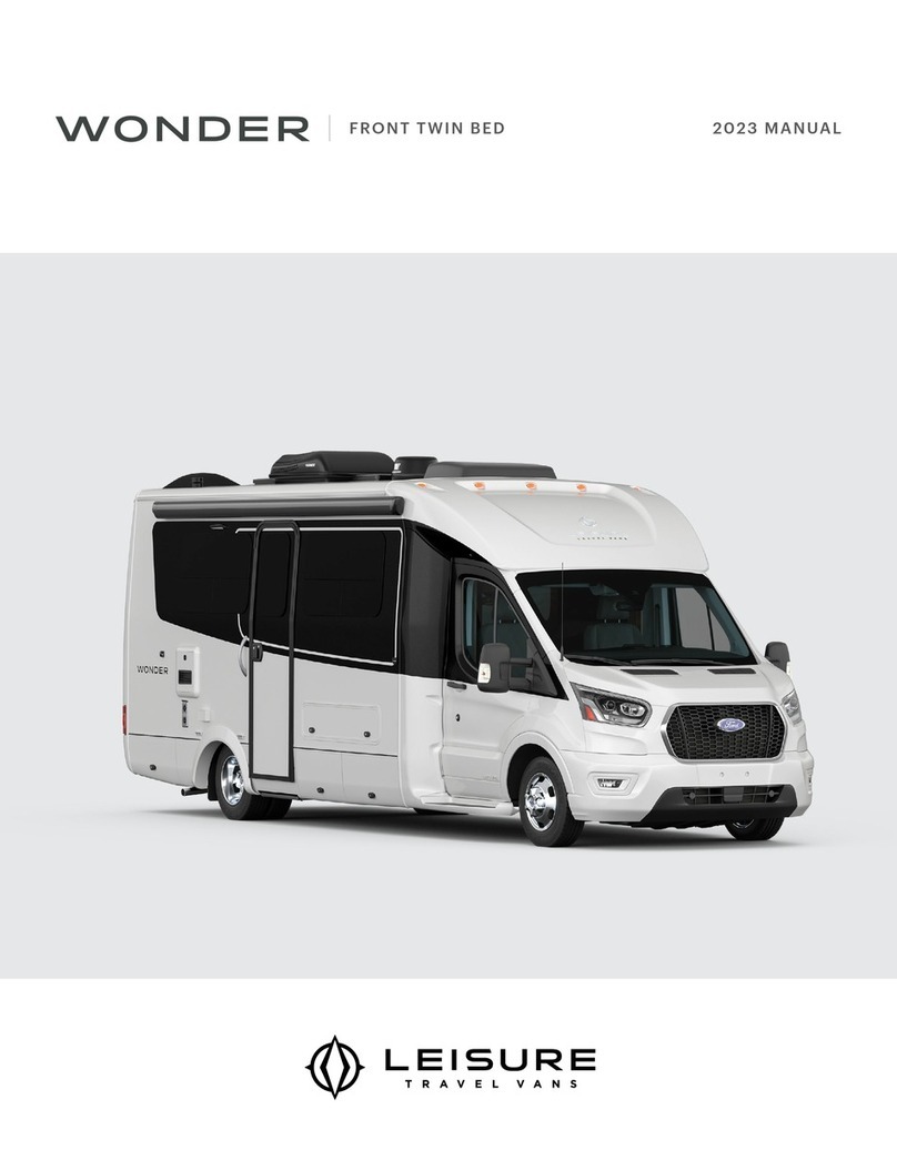
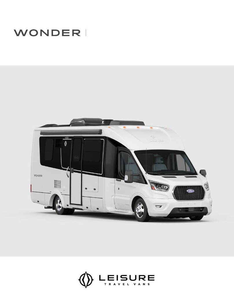
Leisure WONDER 2022 User manual

2022 MANUALREAR TWIN BED


MODEL SPECIFIC MANUAL TABLE OF CONTENTS
REV December 02, 2021 i
TABLE OF CONTENTS
1. INTRODUCTION
Supplemental Manual 11
Motorhome Information Kit 12
Options and Equipment 12
Service Assistance 12
Reporting Safety Defects 13
2. GENERAL INFORMATION
Floor Plan 21
Exterior Equipment Location 22
Beds and Seating 24
3. FIREFLY MULTIPLEX SYSTEM
Home Screen 31
Lights Screen 32
Auto Gen Start Settings Screen 32
Triggers 32
Settings 33
Climate Screen 33
Settings Screen 34
Switch Panels 34
Troubleshooting 35
4. SCHEMATICS
Electrical 41
12 volt Electrical Reference 41
120 Volt Electrical Reference 42
Electrical Schematic 43
Plumbing 48
Water lines schematic 48
Drain line schematic 49
Entertainment 410
Satellite Pre-wire 411


MODEL SPECIFIC MANUAL 1. INTRODUCTION
REV December 02, 2021 11
1. INTRODUCTION
Congratulations! Thank you for selecting a Leisure
Travel Vans Motorhome.
Welcome to the exciting world of motorhome travel
and camping, with all the comforts of home with you,
while you travel and enjoy the outdoors.
Your motorhome has been designed and manufactured
to enhance your travel and camping experience and
to provide you with safe, ecient and trouble-free
operation.
Before your first drive, become familiar with the
operation of the vehicle chassis and all functions and
operations of the motorhome. Spend adequate time
with your dealer when you take delivery to learn all
you can about your new motorhome.
SUPPLEMENTAL MANUAL
This manual was prepared to aid the operator and
occupants in the operation and care of the motorhome
by giving specic information about your model. There
are many options to Leisure Travel Vans, so ensure
that you are familiar with your motorhome’s systems
and equipment. All operators and occupants of the
motorhome should read, understand and follow
the instructions in this manual, the vehicle chassis
manual &the information contained in the Motorhome
Information Kit provided with your new motorhome.
Your motorhome contains a number of systems,
components, equipment, and appliances manufactured
by vendors that supply components for Triple E RV.
These vendors are unrelated to Triple E RV.
Before operating the motorhome for the rst time –
even if an experienced motorhome operator – read
and become familiar with all of the relevant manuals
to your motorhome, components, equipment and
appliances provided in the Motorhome Information
Kit. Your familiarity with the detailed operation of
your motorhome will assist in your safe, ecient and
trouble-free motorhome operation.
KEEP the Motorhome Information Kit within your
motorhome for readily available reference.
PASS this manual, the Chassis Operation Manual and
the Motorhome Information Kit to any subsequent
operator or owner.
For clarication or further details on any of the enclosed
information, please contact:
Your Leisure Travel Vans Dealer orTriple E RV Customer
Service at:
Email: info@tripleerv.com
Toll Free: 8779929906
Telephone: 2043254361
Fax: 2043255241

1. INTRODUCTION MODEL SPECIFIC MANUAL
12 REV December 02, 2021
MOTORHOME INFORMATION KIT
The Motorhome Information Kit includes but isn’t
limited to information on the components, equipment
and appliances listed below (based on options
selected).
•Refrigerator
•Stove top
•Furnace
•Electrical Panel
•Toilet
•Water Heater
•Water Pump
•Water Filtration
•Vent (roof)
•Fire Extinguisher
•Smoke Detector
•Thermostat
•CO Detector
•Propane Detector
•Gas Regulator
•TV Antenna
•TV/DVD
•Chassis
•Air Conditioner
•Generator
•Stabilizers/Leveling Jacks
•Rear View Monitor
•Inverter
•Entertainment System
•Safety
•Flooring and Countertops
•Electric Step
•Solar Panel
•Surge Protector
•Safe
•Awning
OPTIONS AND EQUIPMENT
Leisure Travel Vans are available in various sizes
and floor plan configurations and with differing
optional equipment. The equipment, accessories and
components described in this manual may not apply
in all respects to your motorhome. Read the material
and manuals provided in the Motorhome Information
Kit for detailed instructions regarding the equipment
specic to your motorhome.
SERVICE ASSISTANCE
Your dealer will assist you with any additional
information you need and will answer any questions
you have about the operation of your motorhome.
When it’s time to service the vehicle, remember
that your dealer knows your motorhome best and is
dedicated to your satisfaction. Your dealer will provide
quality maintenance and assistance during your period
ownership. Triple E RV strongly recommends that you
follow a regular maintenance schedule to keep your
motorhome functioning at its best.
Call the following numbers if you require warranty
assistance while traveling:
Triple E RV: 1-877-992-9906
Canada Sprinter Customer Service:
1-800-387-0100 www.thesprinter.ca
US Sprinter Customer Service:
1-877-762-8267 www.mbsprinterusa.com
Canada Ford Customer Service:
1-800-565-3673 www.ford.ca
US Ford Customer Service:
1-800-392-3673 www.ford.com
Emergency Roadside Service* Call:
1-877-219-3831
4287 Beltline Road, Box 198
Addison, Texas 75001
*This Emergency Roadside Service is available to
owner of the motorhome during the rst two years
after purchase.

MODEL SPECIFIC MANUAL 1. INTRODUCTION
REV December 02, 2021 13
REPORTING SAFETY DEFECTS
If you suspect your motorhome has a safety defect
that could cause injury or death, immediately contact
Triple E RV. Also, contact the National Highway Trac
Safety Administration (NHTSA) in the US or Transport
Canada to report your concern.
NHTSA will investigate the concern if there are a
number of similar complaints. NHTSA has the authority
to order a recall and repair campaign depending on
the nature and severity of the problem.
You can reach the NHTSA by calling the Auto Safety
Hot-line at 18004249393 (2023660123 in the
Washington, DC, area) or by writing to NHTSA, US
Department ofTransportation, Washington, DC 20590.
The hot-line also will provide you with additional
information on motor vehicle safety.
In Canada, call 16139939851 or write to Transport
Canada and Road Safety, 2780 Sheeld Road, Ottawa,
Ontario K1B 3V9.


MODEL SPECIFIC MANUAL 2. GENERAL INFORMATION
REV December 02, 2021 21
2. GENERAL INFORMATION
FLOOR PLAN

2. GENERAL INFORMATION MODEL SPECIFIC MANUAL
22 REV December 02, 2021
EXTERIOR EQUIPMENT LOCATION
PASSENGER SIDE VIEW
1
2
34
5
6
7
8
99
1Light
2External Receptacle
3Generator Compartment
4BBQ Hook-Up
5Storage Compartment
6Electrical Step
7Awning
8Ladder (Optional)
9Fridge Vents
DRIVER SIDE VIEW
1
2
34
56
6
7
8
910
1Sewer Termination
2Fuel Fill
3Sewer Hose (Behind Doors)
4Shore Power Connection
5Utility Center
6Storage Compartment
7Propane Shut-O
8Water Heater
9Furnace Vent
10 Battery Compartment

MODEL SPECIFIC MANUAL 2. GENERAL INFORMATION
REV December 02, 2021 23
TOP VIEW
1233
4
1
65
55
6
7
8
9
1Skylight
2Stack Vent
3Roof Vent
4Satellite (Optional)
5Solar Panels (Optional)
6A/C
7Radio Antenna
8TV/WiFi Antenna
9Awning

2. GENERAL INFORMATION MODEL SPECIFIC MANUAL
24 REV December 02, 2021
BEDS AND SEATING
COMBINING THE TWIN BEDS
1.
Flip out the bed extension
1
located between
the beds.
1
2.
Slide the mattresses
2
together to meet in the
center.
22
TO RETURN THE TWIN BEDS TO THEIR
ORIGINAL POSITION:
1. Slide the mattresses back out towards the walls
of the motorhome.
2. Fold the bed extension back in.
REMOVABLE TABLE
There are 2 brackets installed in your motorhome to
which you can mount your removable table:
•Attached to the front Driver Side Dinette 1
•Attached between the rear twin beds 2
21
ATTACHING THE TABLE
1.
Remove table
3
and support
4
from storage
location at the foot of the driver side twin bed.
4
3
2. Loosen handles on support to allow movement.
3. Slide bottom of table support 4in to groove on
table bracket and tighten handle
5
to secure
support in place.
8
7
6
5
4.
Place post on bottom of table
9
in to the opening
at the top of the support 8.

MODEL SPECIFIC MANUAL 2. GENERAL INFORMATION
REV December 02, 2021 25
9
5.
Adjust the position and rotation of the table to
your liking, and tighten handles
6
and
7
to
secure in place.
REMOVING THE TABLE
Follow steps 1 through 5 above in reverse order to
remove and store the table.


MODEL SPECIFIC MANUAL 3. FIREFLY MULTIPLEX SYSTEM
REV December 02, 2021 31
3. FIREFLY MULTIPLEX
SYSTEM
HOME SCREEN
The multiplex Home screen gives a basic control and
information on many of the installed components. To
activate the home screen, simply tap on the Home
icon 1in the left navigation.
1
2
3
4
5
67
8
LIGHTING 2
Lighting buttons will turn Blue while a circuit is on and
Black/White once the circuit has been turned o. This
color change is known as “showing feedback.”
The Light Master controls all interior lights at once.
When Light Master O is pressed, it will remember
which lights were on. Then, when Light Master On
is pressed, it will only turn on the lights that are in
memory.
NOTE: To turn on all lights again, press and hold Light
Master On for at least one second.
ᘐNOTICE
Memory is rewritten each time Light Master O
is pressed. In the case that it is pressed twice
in a row, it will remember that no lights were on
and just touching Light Master On won’t turn
on any lights. Press and hold Light Master On to
turn the lights back on. Note: Light Master On/
O buttons will always appear blue and will not
show feedback at any time.
CLIMATE CONTROL 3
The Home screen also gives you basic information
and control of the climate control. It will display the
current climate control mode, the current temperature,
and allow you to adjust the internal temperature by
touching the up and down arrows.
TANK INFORMATION 4
The Home screen will show the current ll level of
the fresh water, gray, and black tank, as well as the
remaining level of the LP tank.
WATER PUMP 5
Tap the water pump button to toggle the water pump
on/o. The Water Pump icon will be bright blue if the
pump is on.
BATTERY LEVEL INDICATORS 6
These graphics will indicate the battery voltage for the
House and Chassis batteries. The graphics will display
Green while above 12V and Red while below 12V.
GENERATOR CONTROLS 7
The Generator display will show the total number of
generator hours accumulated as well as the current
operating status (running or stopped). Generator hours
are saved to the system, not to the generator itself.
•Gen Start: Press and Hold to start the generator.
Please note that the generator requires a press
and hold because it operates on a one-second
delay as a safety feature to help prevent accidental
generator starts.
•Gen Stop: Press and hold to stop the generator.
SATELLITE POWER (OPTIONAL) 8
If you have the optional Winegard satellite installed,
you will nd an icon that will allow you to turn the power
for the satellite on and o.
NOTE: If you do not have the satellite option installed,
this icon will not be displayed.

3. FIREFLY MULTIPLEX SYSTEM MODEL SPECIFIC MANUAL
32 REV December 02, 2021
LIGHTS SCREEN
This screen will control the lighting for the entire
coach, including the exterior, as well as adjust the
intensity of dimmable lights in the coach. To activate
the Lights screen, simply tap on the Lights icon 1in
the left navigation.
1
To turn individual lights On and O, simply tap the
desired lighting icon once. If the light icon has an
icon, that light is dimmable. To dim the light, just press
and hold the button and the light will begin to cycle
the brightness up and down. Release the button when
the desired lighting is achieved.
AUTO GEN START SETTINGS
SCREEN
The Firey multiplex system is equipped with an AGS
(Auto Gen Start) system that will automatically attempt
to start the generator. To activate the Auto Gen Start
screen, simply tap on the Auto Gen Start icon
2
in
the left navigation.
2
3
To enable AGS, tap on the Enable/Disable toggle
button 3. You will have to conrm you want the AGS
turned on by following the screen prompts.
ᘐWARNING
Enabling AGS in an enclosed or unventilated
space may cause injury or death.
Do not enable AGS without ensuring it is safe
to do so.
TRIGGERS
In order for the AGS to run, it needs a trigger to tell it
when to start. This can be either low battery voltage,
the air conditioner/heat pump, or both. If no triggers
are selected, the AGS will not run.
12
13
11
10
9
8
7
6
54
LOW VOLTS 4
This trigger will cause the generator to start when the
coach batteries fall below a set voltage. To enable the
low volt trigger, ensure AGS is enabled, and tap the
Low Volts button.
HVAC LOAD 5
The HVAC trigger will cause the generatorto start with
the air conditioner or heat pump.
ᘐWARNING
Do not use this trigger if plugged into shore
power.

MODEL SPECIFIC MANUAL 3. FIREFLY MULTIPLEX SYSTEM
REV December 02, 2021 33
SETTINGS
•
Quiet Time Start/Stop
6
:Between these hours,
the AGS will not attempt to automatically start the
generator.
•
Start at
7
:The AGS will start the generator when
the motorhome’s batteries reach this voltage.
•
Time at Start Volts
8
:The amount of time for the
batteries to stay at the set start voltage before the
generator attempts to start.
•Stop at 9:The battery voltage at which the AGS
will turn o the generator.
•Time at Stop Volts 10 : The amount of time for the
batteries to stay at the set stop voltage before the
generator stops.
•
Min Gen Run Time
11
: The minimum amount of
time for the generator to run once started.
•Max Gen Run Time 12 : The maximum amount of
time for the generator to run once started.
•
Gen Start Retries
13
: The amount of times the
AGS will attempt to start the generator if the rst
attempt does not succeed.
CLIMATE SCREEN
Here you will nd the settings for the climate control
of your motorhome. To activate the Climate screen,
simply tap on the Climate icon
14
in the left navigation.
14
15
16 17 18 19
20
Use the arrow keys
15
to select your desired
temperature, and set the climate control type to either
cool, heat pump, furnace, or auto.
•Cool 16 :Tap to operate the air conditioning. The
A/C will run until the current temp reaches your
desired temp and then shut o.
•
Heat Pump
17
:Tap to operate the Heat Pump. The
Heat Pump will run until the current temp reaches
your desired temp and then shut o.
•
Furnace
18
:Tap to operate the Furnace. The
Furnace will run until the current temp reaches
your desired temp and then shut o.
•
Auto
19
: Tap to put the system into Auto mode. The
A/C or Heat Pump will automatically run to keep
your desired temperature consistent.
NOTE: The furnace will not run automatically in auto
mode.
To adjust the fan speed
20
, simply tap on the mode
you would like. The fan will operate by choosing High
or Low. Auto will turn the fan o. Fan Only Mode is only
available if HVAC is o.

3. FIREFLY MULTIPLEX SYSTEM MODEL SPECIFIC MANUAL
34 REV December 02, 2021
SETTINGS SCREEN
The Settings screen contains the general settings for
the multiplex system. To activate the Settings screen,
tap on the Settings icon in the left navigation.
1
2
3
4
5
6
12
CHANGING TEMPERATURE UNITS
To change between Fahrenheit and Celsius for the
climate control, tap on either C or F to set the preferred
units.
SCREEN BRIGHTNESS
Use the +/- buttons to select between 10 levels of
screen brightness or screen sleep mode. Tapping the
screen after it has been asleep will bring it back to
previous brightness.
AUTO DIMMING
When enabled, the screen will enter sleep mode after
60 seconds of inactivity. Tap anywhere on the screen
to wake it up.
SETTING THE TIME
Use the up and down arrows to adjust the hours and
minutes. Select 24-hour time mode or adjust Hour/
Minutes.
CLEANING MODE
Tap to put your screen to sleep for 15 seconds for the
purpose of cleaning.
SWITCH PANELS
You will nd wirelessly connected switch panels
7
with backlit keys throughout the motorhome to control
lights remotely.
7
8
9
10
Lights that are dimmable
8
will have Up/Down arrows
next to the icon. Press and hold these buttons to ramp
the brightness up and down. Each time that a button
is pressed, the Operational LED
9
will illuminate
green to indicate that the command has been sent
to the touchscreen.
The switch nearest the coach entrance also contains
the Step Override switch
10
. Turn the Step Override on
to prevent the steps from retracting when the coach
door is closed.
NOTE: The vehicle ignition switch must be in the “OFF”
position for the step override switch towork.

MODEL SPECIFIC MANUAL 3. FIREFLY MULTIPLEX SYSTEM
REV December 02, 2021 35
TROUBLESHOOTING
If you press a switch panel button and the operational
LED does not illuminate, you’ll need to change the
battery. Simply use your ngers to pry the switch panel
away from the wall-mounted backplate to access the
battery compartment on the back of the switch. These
switches are powered by a 2032 coin cell battery 11 .
11
Once you replace the battery, line the switch panel
up with the backplate and apply pressure to snap the
switch panel back into place.
If the switch panel operational LED lights up but the
lights do not toggle, you may have to re-pair the switch
to the control panel.
1.
From the Settings screen, tap on Switch Panel
Info 12 .
2. Tap on the icon for the switch that is not working
and hold for 3 seconds.
3.
Tap on “Start Pairing” to begin the pairing process.
4. The control panel will begin counting down from
30 seconds. Before the timer runs out, press and
hold 2 buttons on the switch to be paired for 5
seconds.
The control panel should display the pairing was a
success. If it does not, make sure the Operational LED
is lighting up when a button is pressed, and replace
the battery if necessary.

Table of contents
Other Leisure Caravan manuals

Leisure
Leisure UNITY 2017 User manual

Leisure
Leisure WONDER 2024 User manual

Leisure
Leisure UNITY 2023 User manual

Leisure
Leisure WONDER 2023 User manual

Leisure
Leisure WONDER 2023 User manual

Leisure
Leisure UNITY FX 2023 User manual

Leisure
Leisure UNITY 2023 User manual

Leisure
Leisure UNITY 2022 User manual