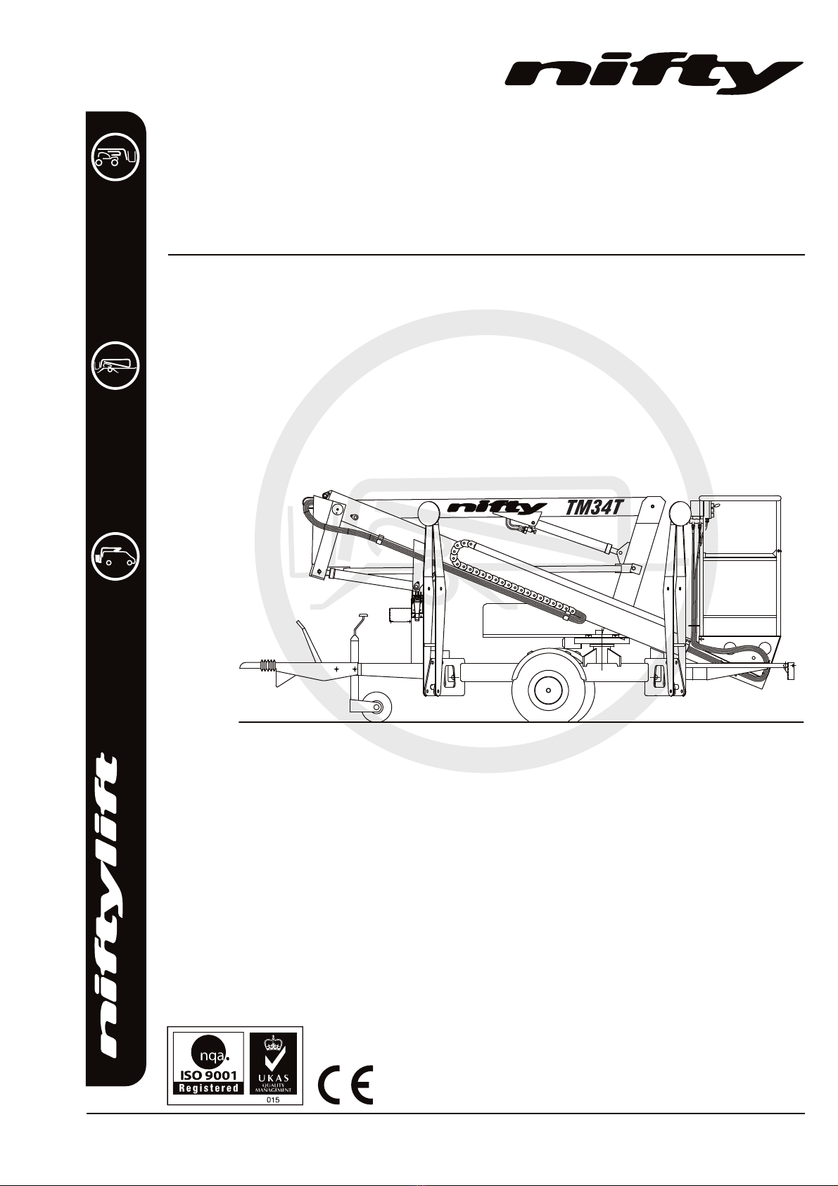
NIFTYLIFT nifty TM Series Quick guide

.com
TM34T
Operating and Safety Instructions
MODEL TM34T SERIES
Niftylift Limited
1525 S.Buncombe Road
Greer
SC 29651
USA
www.niftylift.com
e-mail: niftyusa@niftylift.com
Tel: 864-968-8881
Fax: 864-968-8836
M50400/03


TM Series
Operating & Safety Instructions
USA –04/18
Issue 03
1
Table of Contents
1INTRODUCTION AND GENERAL INFORMATION PAGE
1.1 Foreword 2
1.2 Scope 3
1.3 Introducing the TM34T Trailer Mount (TM) Series 3
1.4 General Specification 4
1.5 Identification 5
1.6 EC Declaration of Conformity 6
2 SAFETY
2.1 Mandatory Precautions 7-9
2.2 Environmental Limitations 10
2.3 Noise & Vibration 10
2.4 Test Report 10
3 PREPARATION AND INSPECTION
3.1 Unpacking 11
3.2 Preparation for Use 11
3.3 Pre-Operational Safety Check Schedules 12-13
3.4 Placard, Decals and Installation 14-16
3.5 Torque Requirements 17
4 OPERATION
4.1 Control Circuit Components 18
4.2 Setting Up Procedures 19
4.3 Ground Control Operation 20-21
4.4 Basket Control Operation 22-23
4.5 Batteries and Charging 24-25
4.6 Transporting, Towing, Craneage, Storage and Setting to Work 26-29
4.7 Traction Drive 30-31
5 EMERGENCY CONTROLS
5.1 General 32
5.2 Emergency Procedures - Incapacitated Operator 32
5.3 Emergency Procedures - Machine Failure 32
5.4 Incident Notification 32
6 RESPONSIBILITIES
6.1 Changes in Ownership 33
6.2 Manual of Responsibilities (USA only) 33
6.3 Inspection/ Service Check List 34-35

TM Series
Operating & Safety Instructions
USA –04/18
Issue 03
2
1 Introduction and General Information
1.1 FOREWORD
The purpose of these manuals is to provide the customer with appropriate safety operating and
maintenance instructions essential for proper machine operation.
All information in these manuals should be READ and fully UNDERSTOOD before any attempt is made
to operate the machine. THESE MANUALS ARE VERY IMPORTANT TOOLS - Keep them with the
machine at all times.
The manufacturer has no direct control over machine application and use, therefore
conformance with good safety practices is the responsibility of the user and his operating
personnel.
All information in these manuals is based on the use of the machine under proper operating
conditions. Alteration and/or modification of the machine are strictly forbidden.
One of the most important facts to remember is that any equipment is only as safe as those
who operate it.
DANGER, WARNING, CAUTION, IMPORTANT, INSTRUCTIONS AND NOTICE
Any place these topics may appear, either in this manual or on the machine, they are defined as
follows:
DANGER: If not correctly followed there is a high probability of serious injury or death to personnel.
WARNING OR CAUTION:If not correctly followed there is some possibility of serious injury or death to
personnel.
THE 'SAFETY ALERT' SYMBOL IS USED TO CALL ATTENTION TO POTENTIAL
HAZARDS THAT MAY LEAD TO SERIOUS INJURY OR DEATH, IF IGNORED.
IMPORTANT AND INSTRUCTIONS: Denotes procedures essential to safe operation and prevention of
damage to or destruction of the machine.
NOTICE: Indicates general safety rules and/or procedures relating to the machine.
It is the owner's/user's responsibility to know and comply with all applicable rules,
regulations, laws, codes and any other requirements applicable to the safe use of this
equipment.

TM Series
Operating & Safety Instructions
USA –04/18
Issue 03
3
1.2 SCOPE
These operating instructions contain all the necessary information required to allow the safe operation
of any Niftylift TM34T, powered by electric (DC), diesel (D), gasoline (G) engine, or a combination of
these.
For further technical information, circuit diagrams and specific instructions for all maintenance which
may need to be carried out by specialist trained personnel, see the associated shematics and Parts
manual for your model of Niftylift TM34T.
1.3 INTRODUCING THE TM34T TRAILER MOUNT (TM) SERIES
Please note at the time of going to press all information, illustrations, details and descriptions contained
herein are valid. Niftylift reserves the right to change, modify or improve its products without any
obligations to install them on previously manufactured machines.
If you require further information after reading this manual, please do not hesitate to contact us.
Niftylift Inc, 1525 S. Buncombe Road, Greer, SC 29651 USA
The Niftylift TM34T trailer mount is an extremely versatile articulated boom platform of unique and
simple design. It is capable of placing two men and their tools up to a height of 40ft or an outreach of
20ft 1in.
The booms are mounted via a 360opowered swing mechanism on to a compact base balanced on a
single axle. The fully articulating booms give an outstanding working envelope. The large pneumatic
wheels and minimal weight make the unit light and simple to manoeuvre.
A simple, all-hydraulic proportional control system gives smooth, reliable movement of the basket and
maximum reliability in the harshest environments.
The hydraulic outriggers make setting up both swift and simple and a unique pressure sensitive
microswitch system fitted to each outrigger prevents operation of the machine until all outriggers have
been correctly deployed. This is coupled with a loud audible alarm warning of a possibly hazardous
situation.
Models include the following:
E: - DC ELECTRIC BE: - BI-ENERGY (DIESEL & BATTERY)
AC: - AC ELECTRIC GE: - BI-ENERGY (GASOLINE & BATTERY)
D: - DIESEL G: - GASOLINE
ACE: - AC & DC ELECTRIC PAC: - PETROL & AC ELECTRIC
DAC: - DIESEL & AC ELECTRIC

TM Series
Operating & Safety Instructions
USA –04/18
Issue 03
4
1.4 GENERAL SPECIFICATION
FEATURE
TM34T
MAXIMUM HEIGHT - WORKING
12.3m
40ft 4in
MAXIMUM HEIGHT - BASKET
10.3m
33ft 9 in
MAXIMUM HEIGHT - STOWED
1.9m
6ft 3in
MAXIMUM OUTREACH
5.9m
19ft 4in
MAXIMUM WIDTH - TOWING
1.5m
4ft 11in
JACK SPREAD
3.55m
11ft 8in
MAXIMUM LENGTH - STOWED
4.45m
14ft 7in
MAXIMUM CAPACITY - (EUROPEAN)
(USA)
200kg (440lbs)
500lb
TURRET ROTATION
360º
TURRET TAIL SWING
Zero
MAXIMUM TRAVEL SPEED
50 mph
80 km/h
BASKET SIZE - LENGTH X WIDTH
0.65m x 1.1m
25in x 44in
CONTROLS
Full proportional hydraulic
HYDRAULIC PRESSURE
200bar
2,900 psi
TYRES
165 R14 C8 175 R14C 8PR (Traction Drive)
4.5 bar (65 psi)
GROUND CLEARANCE
200mm
8in
GROSS VEHICLE WEIGHT (MAXIMUM)
1310kg
2888lbs
MAXIMUM GROUND PRESSURE
0.064kn/cm2
13506lb/ft2
POWER SOURCE
E (Electric) models - 4 x 6v 250 AH batteries
G (Gasoline) models - Honda GX160 Engine
D (Diesel) models - Yanmar L40 or Kubota OC60 engine

TM Series
Operating & Safety Instructions
USA –04/18
Issue 03
5
1.5a IDENTIFICATION PLATE
This manufacturer’s plate is attached to Boom 1 on each machine at the time of
manufacture on every Niftylift. Please ensure all sections have been stamped and
are legible.

TM Series
Operating & Safety Instructions
USA –04/18
Issue 03
6
1.6 EC DECLARATION OF CONFORMITY (Typical)

TM Series
Operating & Safety Instructions
USA –04/18
Issue 03
7
2 Safety
2.1 MANDATORY PRECAUTIONS
When operating your Niftylift, your safety is of utmost concern. In order to fully appreciate all aspects
of the machines operation it should be ensured that each operator has READ and fully UNDERSTOOD
the relevant manual covering machine use, maintenance and servicing. If any doubts exist concerning
any points covered in your manual, contact your local dealer or Niftylift Ltd.
Before using any Niftylift, thoroughly inspect the machine for damage or deformation to all major
components. Likewise, check the control systems for hydraulic leaks, damaged hoses, cable faults or
loose covers to electrical components. At no time should damaged or faulty equipment be used -
Correct all defects before putting the platform to work. If in doubt, contact your local dealer or Niftylift
Ltd (see front cover for address).
THE MANUFACTURER HAS NO DIRECT CONTROL OVER THE MACHINE
APPLICATION AND USE. THEREFORE CONFORMATION WITH GOOD SAFETY
PRACTICES IS THE RESPONSIBILITY OF THE USER AND HIS OPERATING
PERSONNEL. FAILURE TO UNDERSTAND AND FOLLOW ALL SAFETY RULES
COULD RESULT IN SERIOUS INJURY OR DEATH.
2.1.1 Only trained persons will be permitted to operate the Niftylift.
2.1.2 Always operate the Niftylift in full accordance with the manufacturers Operating & Safety Instructions
for that model.
2.1.3 Before use each day and at the beginning of each shift the Niftylift shall be given a visual inspection
and functional test including, but not limited to, operating and emergency controls, safety devices,
personal protective clothing, including fall protection, air, hydraulic and fuel system leaks, cables and
wiring harness, loose or missing parts, tyres and wheels, placards, warnings, control markings and
Operating and Safety Manuals, guards and guard rail systems and all other items specified by the
manufacturer.
2.1.4 Any problems or malfunctions that affect operational safety must be repaired prior to use of the
platform, with specific regard to any safety components refer to the Parts Manual for part numbers and
details. If in doubt, contact Niftylift Ltd (Details on page 3). Ensure wheels are chocked before
carrying out any maintenance that involves handbrake release as described in Section 4.7.2
–Towing.
2.1.5 Always ensure that all warning labels, instructions, placards, control markings and Safety Manuals are
intact and clearly legible. If replacements are required contact your local dealer or Niftylift. Always
observe and obey safety and operating instructions on such labels.
2.1.6 Do not alter, modify or disable in any way the controls, safety devices, interlocks or any other part of
the machine.
2.1.7 Before the Niftylift is used and during use the user shall check the area in which it is to be used for
possible hazards such as, but not limited to, uneven ground drop-offs, holes, bumps, obstructions,
debris, floor and overhead obstructions, high voltage conductors, wind and weather, unauthorised
persons and any other possibly hazardous conditions.

TM Series
Operating & Safety Instructions
USA –04/18
Issue 03
8
2.1.8 Never exceed the maximum basket capacity, as indicated on the decals and machine serial plate.
2.1.9 Never position any part of the Niftylift within the Minimum Approach Distances of any electrical power
line, conductor, or similar stated in Occupational Safety and Health Administration Regulations for CFR
1910.333(c) for Minimum Approach Distance for electrical wires.
1910.333(c)(3)(i)(A)(1): For voltages to ground 50kV or below - 10 feet (305 cm);
1910.333(c)(3)(i)(A)(2): For voltages to ground over 50kV - 10 feet (305 cm) plus 4 inches (10 cm)
for every 10kV over 50kV.
THIS MACHINE IS NOT INSULATED.
If in doubt, contact the appropriate authorities.
2.1.10 On entering the basket, ensure that the drop down entry bar is closed afterwards.
2.1.11 Use of an approved safety belt and lanyard, hardhat and appropriate safety clothing is mandatory.
Fasten harness to designated harness securing points within the basket and do not remove until leaving
the basket whilst in the stowed position.
2.1.12 Always remain standing within the basket. Do not attempt to increase your height or
reach by standing and/or climbing on the basket guardrails or any other object. KEEP
YOUR FEET ON THE BASKET FLOOR. Do not sit, stand or climb on the guardrail,
mid rail or boom linkage. Use of planks, ladders or any other devices on the Niftylift
for achieving additional height or reach shall be prohibited.
2.1.13 Do not use the BASKET levelling system to artificially increase the outreach of the platform. Never use
boards or ladders in the platform to achieve the same result.
2.1.14 Do not use the BASKET to lift overhanging or bulky items that may exceed the maximum capacity or
carry objects that may increase the wind loading on the platform. (e.g. Notice boards etc.)
2.1.15 The Niftylift shall not be operated from a position on trucks, trailers, railway cars, floating vessels,
scaffolds or similar equipment unless Niftylift Ltd in Great Britain approves the application in writing.
2.1.16 Always check the area below and around the basket before lowering or rotating the booms to ensure
that it is clear of personnel and obstructions. Care should be taken when rotating the booms out into
areas where there may be passing traffic. Use barriers to control traffic flow or prevent access to the
machine.
2.1.17 Stunt driving and horseplay, on or around the Niftylift, shall not be permitted.
2.1.18 When other moving equipment and vehicles are present, special precautions shall be taken to comply
with local ordinances or safety standards established for the work place. Warnings such as, but not
limited to, flags, roped off areas, flashing lights and barricades shall be used.
2.1.19 It shall be the responsibility of the user to determine the hazard classification of any particular
atmosphere or location. Aerial platforms operated in hazardous locations shall be approved and of the
type required. ( refer to ANSI/NFPA 505)
2.1.20 The operator shall immediately report to his supervisor any potentially hazardous location(s)
(environment) which become evident during operation.

TM Series
Operating & Safety Instructions
USA –04/18
Issue 03
9
2.1.21 If an operator encounters any suspected malfunction of the Niftylift or any hazard or potentially unsafe
condition relating to capacity, intended use or safe operation he shall cease operation of the Niftylift
and request further information as to safe operation from his management, or owner, dealer or
manufacturer before further operation of the Niftylift.
2.1.22 The operator shall immediately report to his superior any problems or malfunctions of the Niftylift,
which becomes evident during operation. Any problems or malfunctions that affect the safety of
operation shall be repaired prior to continued use.
2.1.23 The boom and platform of the Niftylift shall not be used to jack the wheels off the ground.
2.1.24 The Niftylift shall not be used as a crane.
2.1.25 The Niftylift shall not be positioned against another object to steady the platform.
2.1.26 Care should be taken to prevent rope, electric cords and hoses from becoming entangled in the aerial
platform.
2.1.27 Batteries shall be recharged in a well-ventilated area free of flame, sparks or other hazards that may
cause explosion. Highly explosive hydrogen gas is produced during the charging process.
2.1.28 When checking electrolyte levels, great care should be taken to protect eyes, skin and clothing. Battery
acid is highly corrosive and protective glasses and clothing is recommended.
2.1.29
When the machine is not in use always stow the booms correctly. NEVER LEAVE
THE KEYS IN THE MACHINE,if it is to be left for any period of time. Use wheel
chocks if leaving on an incline.
2.1.30 If the basket or elevating assembly becomes caught, snagged or otherwise prevented from normal
motion by adjacent structure or other obstacles, such that control reversal does not free the basket, all
personnel shall be removed from the basket safely before attempts are made to free the basket using
ground controls.
2.1.31 The engine must be shut down while fuel tanks are being filled. Fuelling must be done in a well-
ventilated area free of flame, sparks or any other hazard that may cause fire or explosion. GASOLINE,
LIQUID PROPANE AND DIESEL FUELS ARE FLAMMABLE.
2.1.32
NEVER START THE NIFTYLIFT IF YOU SMELL GASOLINE, LIQUID PROPANE
OR DIESEL FUEL. THESE FUELS ARE HIGHLY FLAMMABLE
2.1.33 The operator must ensure that engine powered machines are used in a well-ventilated area to minimise
the risk of carbon monoxide poisoning.
2.1.34 The operator shall implement means provided to protect against use by unauthorised persons.
2.1.35 Never remove anything that may affect the stability of the machine such as, but not limited to, batteries,
covers, engines, tyres or ballast.
2.1.36 The operator must ensure that the controls are not obstructed (e.g. by tools or equipment) and clear
access to the Emergency Stop is available at all times.

TM Series
Operating & Safety Instructions
USA –04/18
Issue 03
10
2.1.37 All persons in the cage must take suitable precautions to prevent items falling or being ejected from the
cage. E.g. Tethering tools to the machine or operator if practical and an assessment of any resulting
risks is acceptable.
2.2 ENVIRONMENTAL LIMITATIONS
All Niftylift Trailer Mounts are limited to operation as previously described and any slopes must be
adjusted by use of the outriggers and jacks. Unless specifically configured otherwise, the machine will
have short time rating for operation in extreme temperatures, i.e. reduced battery cycle times for low
temperatures such as freezers, food storage etc. and cooling limitations for high temperatures as oil
temperature must remain between -23° and 90° Celsius.
Extended operation in dusty environments is not recommended and frequent cleaning will be necessary.
All dust, dirt, salt encrustation, excess oil or grease should be removed. Deposits of paint or bitumen,
particularly on legends or labels should also be removed.
All standard Niftylift machines are rated for a wind speed of 12.5 m/s, which equates to 28mph or
force 6 on the Beaufort scale. No attempt should be made to operate a Niftylift in wind strengths above
this limit and if the operator has any doubts over the wind speed he / she should cease operation
immediately until it can be established that the wind speed has fallen to a safe level.
DO NOT USE THE NIFTYLIFT IN ELECTRICAL STORMS
2.3 NOISE AND VIBRATION
The airborne noise emission on the TM34T range of machines does not exceed 85dB(A), measured at
a perpendicular distance of 14 feet, under equivalent continuous A-weighted sound pressure test
conditions. This was based on a Diesel powered machine, working under load. All other models will
exhibit significantly lower emissions than this figure, dependant on power option.
In normal operation the Vibration level to which the operator is subjected will not exceed a weighted
root mean square acceleration value of 2.5 m/s2.
2.4 TEST REPORT
All Niftylift machine models are subjected to a comprehensive ‘type test’ which duplicates all
combinations of safe working load (SWL), overload, windage, inertia and pull force to assess the
various safe stability criteria. Self propelled machines are also subjected to kerb and braking tests at
the SWL to satisfy additional ‘worse case’ stability requirements.
Each individual machine is then subjected to static overload tests on flat level ground with 150% of the
SWL, exceeding the requirements of EN280 for power operated MEWPs. Self propelled machines are
also tested at the maximum working angle plus 0.5º with a test load of 125% of the SWL. Finally, on all
machines, a functional test is performed with 110% of SWL.
All safety devices are checked for correct operation, operating speeds are checked against benchmark
figures and the dynamic functions ensure that all acceleration and deceleration forces are within
acceptable limits. All noted defects are rectified and recorded before the machine is permitted to enter
into service.

TM Series
Operating & Safety Instructions
USA –04/18
Issue 03
11
3 Preparation and Inspection
3.1 UNPACKING
Since the manufacturer has no direct control over the shipping or carriage of any Niftylift it is the
responsibility of the dealer and/or owner and/or hirer to ensure the Niftylift has not been damaged in
transit and a Pre-operational Report has been carried out by a qualified engineer before the aerial
platform is put into service.
A) Remove all ropes, straps and or chains used to secure the aerial platform during transit.
B) Ensure any ramp, loading dock or forklift used is capable of supporting or lifting the aerial
platform.
***Carry out the Pre-operational Report before placing machine in service.
3.2 PREPARATION FOR USE
Whilst every effort has been made at the Niftylift factory to ensure your machine arrives in a safe and
operable condition it is necessary to carry out a systematic inspection prior to putting the aerial
platform into service.
THIS IS NOT A REQUEST IT IS MANDATORY
To assist the user in this task you will find enclosed an Inspection Check List (see section 6.3), which
must be filled out upon delivery/receipt of the machine.
Before the user carries out the Inspection Check List he must have read and fully understood all the
contents of the Operating, Safety and Maintenance Manual.
WARNING - DO NOT OPERATE A POTENTIALLY DEFECTIVE OR
MALFUNCTIONING MACHINE. CORRECT AND REPAIR ANY DEFECTS
BEFORE OPERATING YOUR NIFTYLIFT.

TM Series
Operating & Safety Instructions
USA –04/18
Issue 03
12
3.3 PRE-OPERATIONAL SAFETY CHECK SCHEDULES
Before use at the beginning of the work shift, the aerial platform shall be given a visual inspection and
functional tests including, but not limited to the following. It is recommended that these be performed
at regular intervals as indicated on each checklist.
3.3.1 DAILY SAFETY CHECKS
1) Check that all labels (decals) are in place and legible.
2) Visually inspect the machine for damaged or loose components.
3) Check that batteries are charged.
4) Check the fuel level (if applicable).
5) Check that canopies/covers and guards are in place and secure.
6) Check that the boom rest switch is operable (if applicable).
7) Check that control levers are secure and operate freely.
8) Check that operating buttons and emergency stop buttons function properly.
9) Check the operation of the emergency hand pump.
10) Visually inspect all hydraulic hoses and fittings for damage or leaks.
11) Check operation of the stabiliser alarm.
12) Check that outrigger footpads are secure.
13) Check that the platform pivot pins and their tag bolts are secure.
14) Check security and operation of the boom clamp.
15) Check the operation of the cage weigh system (If fitted).
16) Check that warning lights, beacons and sounders function correctly.
3.3.2 WEEKLY SAFETY CHECKS
The weekly, monthly and annual safety checks should be carried out by a qualified person and shall
include checks carried out in Section 3.3.1 with the following additions;
1) Inspect tyres and wheels for damage and wear.
2) Check tyres for correct pressure. 65psi (4.5 bar)
3) Check fenders for security and damage.
4) Check battery fluid levels and specific gravity (after charging) and general condition.
5) Check hydraulic oil level, ISO Grade 32
6) Inspect the engine air filter and clean or replace if necessary.
7) Check that the tow hitch ball lock, breakaway cable/chain and jacking wheel are secure.
8) Check operation and security of outrigger micro switches in conjunction with the alarm system.

TM Series
Operating & Safety Instructions
USA –04/18
Issue 03
13
9) Inspect hose track for damage or missing parts.
10) Check operation of the tilt sensor.
3.3.3 MONTHLY SAFETY CHECKS
1) Check the engine oil level (if applicable).
2) Check the wheel nuts (Refer to Section 3.5).
3) Check outriggers for condition, security and operation.
4) Check that the rotation gear worm is secure and correctly in mesh. Clean and re-grease.
5) Inspect brakes for operation and wear.
6) Grease the knuckle and centre post.
7) Inspect the engine fuel tank for damage or leaks.
8) Check telescopic boom wear pads and nylon studs (if applicable).
9) Check that the end cap on the main knuckle pin is secure and the roll pin is in place.
10) Grease the tow hitch assembly.
11) Lightly oil the jack pad ball joints and outrigger housings.
12) Lightly oil the locating pins on outriggers and axles and the axle clamp bolts.
13) Check and adjust if necessary the Nylatron studs around the telescope boom.
14) Check the condition of the fuel filter and hydraulic oil filter.
3.3.4 ANNUAL SAFETY CHECKS
1) Check that all pivot pins and their tag bolts are secure.
2) Inspect for any cracks or badly rusted areas on booms and chassis.
3) Change the hydraulic oil and the oil filters.
4) Inspect the suspension on each axle unit.
5) Check that rotation gear ring bolts are secure (torque 206ft lbs. 279Nm).
6) Check hydraulic pumps and motors for cracks and leaks, loss of operating speed, excessive
heating of fluid and pressure loss.
7) Check hydraulic cylinders for drifting caused by fluid leak across the holding valve or piston, rod
seal leakage, scored or nicked cylinder rods, dented barrel and unusual noises or vibration.

TM Series
Operating & Safety Instructions
USA –04/18
Issue 03
14
3.4 PLACARD, DECALS & INSTALLATION
ITEM
DESCRIPTION
NUMBER
QTY
1
Daily Safety Checks
P14908
1
2
Tilt alarm
P18842
2
3
General Crush
P14782
10
4
Before Towing
P17341
3
5
Boom Clamp
P19740
1
6
Coupling instructions
P14896
1
7
Harness Point
P14883
2
8
Are you trained?
P22055
1
9
Tyre Pressure 65 psi
P14876
2
10
No Step
P14785
7
11
Emergency Hand Pump
P19090
1
12
Cage Gate Warning
P18432
1
13
General Warning
P21970
2
14
Head Protection
P14921
1
15
Serial Plate
P15383
1
17
SWL 200kg
P14801
1
18
Nifty 120T
P14598
2
19
Niftylift.com
P14390
1
20
Push and Release
P19092
1
21
Cage levelling
P10853
1
22
Point Load - 9.4kN
P14962
4
23
Outriggers - Hydraulic
P14841
4
24
Outrigger Controls
P14922
1
25
Hydraulic Controls –3 lever
P14926
1
26
Hydraulic Controls –5 lever
P14927
1
27
Base Control Cage weigh
Non cage weigh
P17219
P15881
1
1
28
Warning Stripes
A/R
29
Battery Isolator
P18600
1
30
General Notice
P18863
1
31
Battery Charger
P14904
1
32
Cage Control (E/AC) Cage weigh
Non cage weigh
P17212
P15925
1
1
33
Hydraulic Oil ISO32
P17226
1
34
Gasoline Off
P19055
1
35
Diesel ONLY
P14414
1

TM Series
Operating & Safety Instructions
USA –04/18
Issue 03
15
ITEM
DESCRIPTION
NUMBER
QTY
36
Cage Control Cage weigh
Non cage weigh
P17457
P15924
1
1
37
Operating instructions
P14892
1
38
Emergency Controls
P22877
1
39
Overload Warning
P18848
2
40
Noise Warning 85dB
P17124
1
41
Traction Drive - Engage
P18890
1
42
Hand Crush
P14782
2
43
Blank Axle Plate
P16190
1
44
If E-Stop disabled…
P14864
2
45
Tow hitch (Australia/NZ)
P17970
1
46
Traction Drive –Release
P18975
1
47
Traction Drive –On slope
P18976
1
48
Power to cage socket
P24787
1
49
Charger Socket
P19699
1

TM Series
Operating & Safety Instructions
USA –04/18
Issue 03
16

TM Series
Operating & Safety Instructions
USA –04/18
Issue 03
17
3.5 TORQUE REQUIREMENTS
BOLT QUALITY/SIZE
Tightening torque in lbs ft (Nm)
Plated
Unplated
Grade
8.8
10.9
12.9
8.8
10.9
12.9
M6
5 (7)
8 (10)
9 (12)
6 (8)
8 (11)
10 (13)
M8
13 (17)
18 (25)
22 (29)
14 (19)
20 (27)
23 (32)
M10
25 (34)
36 (49)
43 (58)
27 (37)
40 (54)
46 (63)
M12
43 (58)
63 (85)
73 (99)
47 (63)
69 (93)
80 (108)
M14
68 (93)
100 (135)
117 (158)
74 (101)
109 (148)
127 (172)
M16
106 (143)
154 (209)
180 (245)
115 (156)
168 (228)
197 (267)
M20
212 (288)
301 (408)
352 (477)
224 (304)
328 (445)
384 (521)
M24
362 (491)
515 (698)
602 (806)
383 (519)
561 (760)
656 (889)
WHEEL NUTS Sliding axle
Fixed axle
80ft lbs (110 Nm)
M12 - 70ft lbs (95Nm), M14 - 110ft lbs (150 Nm)
SLEW RING BOLTS
206ft lbs (279 Nm)
This torque chart is based on the following assumptions:
1) Bolts to ISO 898-1 "Mechanical properties of fasteners made of carbon steel and alloy steel"
2) For "unplated" bolts, all grades:
Hex head bolts
Black oxide steel bolt with a rolled & oiled thread, no finish on steel nut
Prevailing torque includes Nylock (minimum prevailing torque figure assumed)
Medium Clearance holes to ISO 273
Bolt tightening condition = Yield factor of 75%
3) For "plated" bolts, all grades:
Hex head bolts
Zinc plated oiled (rolled or cut) steel external thread with no finish on steel internal thread
Prevailing torque includes Nylock (minimum prevailing torque figure assumed)
Medium Clearance holes to ISO 273
Bolt tightening condition = Yield factor of 75%
Figures quoted in Nm have been calculated in Nm and then rounded to the nearest whole number.
Figures quoted in lb-ft have been calculated in Nm, converted using a factor of 0.737561 and then
rounded.

TM Series
Operating & Safety Instructions
USA –04/18
Issue 03
18
4 Operation
4.1 CONTROL CIRCUIT COMPONENTS
4.1.1 CONTROL BOARD: -Situated under the canopy, the control box contains all of the wiring and relays to
control the machine operation. The control box is common between models with the same power
source, and will contain, where appropriate, discrete fuses for the circuits concerned.
4.1.2 KLAXON: - Mounted under the control board box is a klaxon. It is this device that sounds continuously
if a jack goes light during operation, (i.e. when the booms are raised) warning the operator of this
condition. If the operator attempts to activate the machine by turning the key switch at the base control
unit to the “ON” position and pushing the green button before the jacks are deployed, the klaxon will
also sound indicating to the operator that the jacks are not setup correctly.
4.1.3 BOOM-SWITCH: - Mounted between the two main booms near the knuckle and operated by a cam,
this switch controls the changeover function between jacks and basket. The jack control function is not
available unless this switch is engaged with the boom, ensuring that the machine must be stowed to
operate the hydraulic jacks. It is also similarly linked into the platform control circuit, such that if the
switch is not engaged with the booms, (i.e. machine is in operation) then the outrigger sensors are
active and would warn the operator of an unsafe condition, should one of them loose contact with the
ground. These control functions are of primary importance to safety of the machine and operator;
under no circumstances should this control function be isolated or by-passed.
4.1.4 BATTERY ISOLATOR: - A grey battery isolator handle is located beneath the canopy which allows the
machine control and power circuits to be isolated from the batteries themselves. Under normal
operation, the machine Key switch should be used to isolate the machine with the Battery Isolator only
being required to disconnect the batteries for maintenance or in the event of a short circuit. The battery
charging circuit is connected directly to the battery side, so charging is un-affected by use of this
switch.
4.1.5 POWER SOURCE SELECTION: - On multiple power option machines, the machine is fitted with an
‘instinctive’ circuit for power source selection. Pressing the green button will automatically select
battery operation. The engine can be started using the two position START/STOP selector in the
platform and the machine will ‘default’ to engine operation via a flow switch in the hydraulic circuit.
Stopping the engine by selecting STOP on the two position selector in the platform and pressing the
green button will return the machine to battery mode.
4.1.6 DIESEL ENGINE: - Generally a Yanmar L40 or Kubota 0C60 engine, described in the maintenance
section of the Workshop Manual, driving a single bodied pump with direct mounted pump dump valve.
4.1.7 GASOLINE ENGINE: - Generally a Honda GX 160 engine, described in the maintenance section of the
Workshop Manual, driving a single body pump with direct mounted pump dump valve.
This manual suits for next models
3
Table of contents
Other NIFTYLIFT Boom Lift manuals

NIFTYLIFT
NIFTYLIFT HR 10 Quick guide

NIFTYLIFT
NIFTYLIFT TM Series Quick guide

NIFTYLIFT
NIFTYLIFT Heightrider HR28 Series Quick guide

NIFTYLIFT
NIFTYLIFT nifty 90 Setup guide

NIFTYLIFT
NIFTYLIFT HR12LE MK2 User manual

NIFTYLIFT
NIFTYLIFT HR 12 Assembly instructions

NIFTYLIFT
NIFTYLIFT SP34 Reference guide

NIFTYLIFT
NIFTYLIFT Nifty Heightrider HR21 MK2 Series Assembly instructions