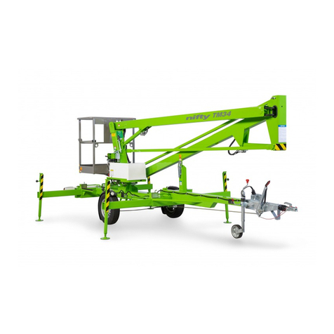
NIFTYLIFT nifty 90 Setup guide

90
TM25
illustrated parts manual
Manuel illustré de pièces détachées
Illustrierte Stückliste
Manual de piezas ilustrado
M50100/04
Issue 4
(October 2009)


90 (TM25)
issue 04
illustrated parts manualManuel illustré de pièces détachées Illustrierte Stückliste Manual de piezas ilustrado
Please Note, at the time of going to press, all information, illustrations details and descriptions
contained herein are valid. Niftylift reserves the right to change, alter, modify or improve its
products without any obligation to install them on previously manufactured machines.
Readers of this manual requiring further information should contact us at:
Niftylift Ltd. Niftylift Inc.
Fingle Drive 32 Concourse Way
Stonebridge Greer
Milton Keynes SC 29651
MK13 OER USA
United Kingdom
Tel +44 (0)1908 857899 1 864 968 8881
Fax +44 (0)1908 227460 1 864 968 8836
Ordering of Parts
When ordering a replacement part for your Niftylift product, please state the following:
• Machine Model and Serial number Niftylift Part number
• Full description of the part Quantity required
• Purchase Order number Destination address
Machine Information
Model number. . . . . . . . . . . . . . . . . . . . . . . . . . . . . Date of Purchase. . . . . . . . . . . . . .
Serial number . . . . . . . . . . . . . . . . . . . . . . . . . . . . .
Veuilleznoterqu'aumomentdelamisesouspresse,l'ensembledesinformations,illustrations,détails
et descriptions, contenus dans le présent document, sont valides. Niftylift se réserve le droit de
changer ou d'améliorer ses produits sans obligation de montage sur les anciennes machines.
Pour toutes informations supplémentaires, veuillez nous contacter à:
Niftylift Ltd. Niftylift Inc.
Fingle Drive 32 Concourse Way
Stonebridge Greer
Milton Keynes SC 29651
MK13 OER USA
United Kingdom
Tel +44 (0)1908 857899 1 864 968 8881
Fax +44 (0)1908 227460 1 864 968 8836
Commande de pièces
Lors de la commande de pièces de rechange pour votre machine Niftylift, veuillez indiquer ce qui suit:
• Modèle et numéro de série de la machine Référence de la pièce Niftylift
• Description complète de la pièce Quantité requise
• Numéro de commande Adresse de destination
Informations relatives à la machine
Numéro de modèle. . . . . . . . . . . . . . . . . . . . . . . . . . . Date d'achat. . . . . . . . . . . . . . . . . . .
Numéro de série . . . . . . . . . . . . . . . . . . . . . . . . . . . . .

90 (TM25)
iv issue 04
illustrated parts manual Manuel illustré de pièces détachées Illustrierte Stückliste Manual de piezas ilustrado
Bitte nehmen Sie zur Kenntnis, dass alle hierin enthaltenen Informationen, Illustrationen und
Beschreibungen zum Zeitpunkt des Drucks gültig sind. Niftylift behält sich das Recht vor, Produkte zu
wechseln, ändern, modifizieren und zu verbessern, ohne verpflichtet zu sein, sie an früher gefertigten
Maschinen zu installieren.
Wenn Leser dieser Anleitung weitere Informationen benötigen, wenden sie sich bitte an uns unter:
Niftylift Ltd. Niftylift Inc.
Fingle Drive 32 Concourse Way
Stonebridge Greer
Milton Keynes SC 29651
MK13 OER USA
Großbritannien
Tel +44 (0)1908 857899 1 864 968 8881
Fax +44 (0)1908 227460 1 864 968 8836
Bestellen von Ersatzteilen
Bei der Bestellung eines Ersatzteils für Ihr Produkt von Niftylift geben Sie bitte folgende Einzelheiten an:
• Maschinenmodell und Seriennummer Niftylift Art.-Nr.
• Ausführliche Beschreibung des Teils Erforderliche Menge
• Bestellnummer Bestimmungsadresse
Maschineninformationen
Modellnummer . . . . . . . . . . . . . . . . . . . . . . . . . . . . . . Kaufdatum. . . . . . . . . . . . . . . . . . . .
Seriennummer. . . . . . . . . . . . . . . . . . . . . . . . . . . . . . .
Por favor, observe que en el momento de pasar a imprenta, toda la información, ilustraciones y
descripciones contenidas en el presente documento eran válidas. Niftylift se reserva el derecho de
cambiar, alterar, modificar o mejorar sus productos, sin obligación alguna de instalar dichos cambios en
máquinas fabricadas anteriormente.
Los usuarios de este manual que requieran más información, deberán ponerse en contacto con
nosotros en:
Niftylift Ltd. Niftylift Inc.
Fingle Drive 32 Concourse Way
Stonebridge Greer
Milton Keynes SC 29651
MK13 OER USA
United Kingdom
Tel +44 (0)1908 857899 1 864 968 8881
Fax +44 (0)1908 227460 1 864 968 8836
Pedido de piezas
Al realizar el pedido de una pieza de recambio para su producto Niftylift, sírvase especificar lo siguiente:
• Modelo y número de serie de la máquina Número de pieza Niftylift
• Descripción completa de la pieza Cantidad requerida
• Número de orden de compra Dirección de destino
Información de la máquina
Número de modelo. . . . . . . . . . . . . . . . . . . . . . . . . . . Fecha de compra. . . . . . . . . . . . . . .
Número de serie . . . . . . . . . . . . . . . . . . . . . . . . . . . . .

Parts Order Form (make copies for use)
Bon de commande de pièces (Faire des photocopies pour vos commandes ultérieures) tel +44 (0)1908 857899
Bestellformular für Ersatzteile (bitte Kopien zur zukünftigen Verwendung machen) fax +44 (0)1908 227460
Impreso de pedido de piezas (haga copias para el uso) www.niftylift.com
Note; Ifitems havedecals/labels attached,these arenot included (unless statedotherwise),theymust beordered separatelyusing
the part (P) number printed on the decal.
Remarque : si les composants sont dotés d'autocollants/étiquettes, ceux-ci ne sont pas inclus (sauf avis contraire). Ils doivent être
commandés séparément en indiquant le numéro de référence (P) imprimé sur l'autocollant.
Anmerkung: Wenn an Gegenständen Klebebilder/Etiketten angebracht sind, sind diese (sofern nicht anders angegeben) nicht en-
thalten und müssen separat mit Hilfe der auf den Klebebildern abgedruckten Teilenummern (P) bestellt werden.
Nota: Silos artículos llevanacopladascalcomanías/etiquetas,éstas no se incluirán (amenosqueseindique locontrario);deberán
pedirse por separado utilizando el número de pieza (P) impreso en la calcomanía.
Part Number
Référence pièce
Art.-Nr.
Número de pieza
description
description
beschreibung
descripción
quantity
quantité
menge
cantidad
price
prix
preis
precio
P
P
P
P
P
P
P
P
name nom name nombre
address adresse adresse dirección
telephone téléphone tel.-Nr. teléfono
fax fax-Nr.
email e-mail
date date datum fecha
delivery address
adresse de livraison
lieferadresse
dirección de entrega
purchase order number
numéro de commande
bestellnummer
número de orden de compra

90 (TM25)
vi
illustrated parts manual Manuelillustrédepiècesdétachées IllustrierteStückliste Manual de piezas ilustrado
table des matières
inhaltsverzeichnis
tabla del contenido
contents
issue 04
1
chassis
page
1.1 Base assembly (without braking system).............................................................. 1-2
1.2 Base assembly (with braking system)................................................................... 1-6
1.3 Manual jack assembly......................................................................................... 1-10
1.4 Tow coupling assembly (Euro/Australia)............................................................ 1-12
1.5 Tow coupling assembly (USA) ........................................................................... 1-14
1.6 Jockey wheel assembly...................................................................................... 1-16
1.7 Wheel hub assembly (Unbraked)....................................................................... 1-18
1.8 Wheel hub assembly (Braked)............................................................................ 1-20
1.9 Lighting board assembly .................................................................................... 1-22
2
superstructure
page
2.1 Power tray (Battery DC)......................................................................................... 2-2
2.2 Power tray (Mains AC)........................................................................................... 2-4
2.3 Slew assembly ....................................................................................................... 2-6
2.4 Control valve assembly (3 spool) .......................................................................... 2-8
2.5 DC Power pack .................................................................................................. 2-10
2.6 AC Power pack.................................................................................................... 2-12
2.7 AC transformer box............................................................................................. 2-14
2.8 Battery charger.................................................................................................... 2-16
2.9 Dual voltage charger box ................................................................................... 2-18
2.10 Button box assembly .......................................................................................... 2-20
3
boom assemblies
page
3.1 Booms assembly.................................................................................................... 3-2
3.2 Lift cylinder............................................................................................................. 3-4
4
cage
page
4.1 Cage assembly ...................................................................................................... 4-2
4.2 Cage weigh assembly (Load Cell) ........................................................................ 4-4
4.3 Cage weigh assembly (Spring) ............................................................................ 4-6
4.4 Control valve assembly (3 spool) .......................................................................... 4-8
4.5 Button box assembly .......................................................................................... 4-10
5
labelling
page
5.1 Label Locations 90................................................................................................. 5-2

90 (TM25)
vii
contents
illustrated parts manualManuel illustré de pièces détachées Illustrierte Stückliste Manual de piezas ilustrado
table des matières
inhaltsverzeichnis
tabla del contenido
issue 04
6
hydraulic hoses
page
6.1 Hose kit 90 ............................................................................................................. 6-2
Figures
page
1.1 Base assembly (Unbraked) .............................................................. 1-3
1.2 Base assembly (Braked)................................................................... 1-7
1.3 Manual jack assembly..................................................................... 1-11
1.4 Tow coupling assembly (Euro)....................................................... 1-13
1.5 Tow coupling assembly (USA)........................................................ 1-15
1.6 Jockey wheel assembly.................................................................. 1-17
1.7 Wheel hub assembly (Unbraked)................................................... 1-19
1.8 Wheel hub assembly (Braked)........................................................ 1-21
1.9 Lighting board assembly................................................................. 1-23
2.1 Power tray (Battery DC) .................................................................... 2-3
2.2 Power tray (Mains AC) ...................................................................... 2-5
2.3 Slew assembly .................................................................................. 2-7
2.4 Control valve assembly (3 spool)...................................................... 2-9
2.5 DC Power pack .............................................................................. 2-11
2.6 AC Power pack................................................................................ 2-13
2.7 AC transformer box......................................................................... 2-15
2.8 Battery charger................................................................................ 2-17
2.9 Dual voltage charger ...................................................................... 2-19
2.10 Button box....................................................................................... 2-21
3.1 Booms assembly............................................................................... 3-3
3.2 Lift cylinder........................................................................................ 3-5
4.1 Cage assembly.................................................................................. 4-3
4.2 Cage weigh assembly (Load Cell).................................................... 4-5
4.3 Cage weigh assembly (Spring)......................................................... 4-7
4.4 Control valve assembly (3 spool)...................................................... 4-9
4.5 Button box....................................................................................... 4-11
5.1 Label locations 90............................................................................. 5-3
5.2 Labels (1-26 )................................................................................... 5-14
5.3 Labels (27-32) ................................................................................. 5-15
6.1 Hose connections ............................................................................. 6-3

90 (TM25)
viii issue 04
illustrated parts manual Manuel illustré de pièces détachées Illustrierte Stückliste Manual de piezas ilustrado
Issue Records
Chapter Pages Issue Date Comments/Changes
Introduction 8 4 10/2009 Fourth issue
1 24 4 10/2009 Revisions on pages 1-2 to 1-9
2 22 4 06/2010 Revisions on pages 2-4 and 2-12/13
3 6 4 10/2009 Revisions on pages 3-2/3
4 12 3 10/2006 Revisions on all pages
5 16 3 01/2009 Revisions on all pages
6 4 1 07/2003 First issue
*When ordering parts for machines other than the stated serial number,
it is advisable to contact the Parts Department;
United Kingdom USA
Tel +44 (0)1908 857899 1 864 968 8881
Fax +44 (0)1908 227460 1 864 968 8836

90 (TM25)
1
illustrated parts manual
Manuel illustré de pièces détachées
Illustrierte Stückliste
Manual de piezas ilustrado
chassis assembly
french
german
spanish

90 (TM25)
1–2
chassis assembly french
german
spanish
illustrated parts manual Manuelillustré de pièces détachées Illustrierte Stückliste Manualdepiezasilustrado
issue 04
1.1 Base assembly (without braking system)
Item Description Part Number
1Gear wheel P10013
2Bush P10006
3Base P21147
4Axle assembly P10219
5Mudguard bracket P16695
6Rubber grommet P15087
7Mudguard P16569
8Wheel & Tyre
Standard
Heavy Duty P10717
P16028
9
Stabiliser arm
(LH front, RH rear)
Includes item 18
Standard
French P21570
P70239
10
Jockey wheel assy
See “Jockey wheel
assembly” on
page 1-16.
P11664
11 Tow coupling P10220
12 Breakaway cable P17922
13 Locating pin P11377
14 Roll pin P10669
15 Spring P10003
16 Microswitch P18937
17
Jack assembly
(Includes item 18)
See “Manual jack
assembly” on
page 1-10.
P10194
18
Barrel nut
See “Manual jack
assembly” on
page 1-10.
P70073
19
Stabiliser arm
(RH front, LH rear)
Includes item 18
Standard
French P21571
P70238

90 (TM25)
french
german
spanish
chassis assembly
1–3
illustrated parts manualManuel illustré de pièces détachées IllustrierteStückliste Manual de piezas ilustrado
issue 04
16
15
17
19 18
64
8
1
19
49
5
23
9
13
15 2
3
14
6 7 8
17
10
17
17
11
12
14
13
25
24
21
7
15
20
14
22
Figure 1.1 Base assembly (unbraked)

90 (TM25)
1–4
chassis assembly french
german
spanish
illustrated parts manual Manuelillustré de pièces détachées Illustrierte Stückliste Manualdepiezasilustrado
issue 04
1.1 continued
Item Description Part Number
20 Axle housing P21562
21 Locating pin P11267
22 Axle lock bolt P10190
23 Suspension rubber P10226
24 Tie plate P21032
25 Junction box P10077

90 (TM25)
french
german
spanish
chassis assembly
1–5
illustrated parts manualManuel illustré de pièces détachées IllustrierteStückliste Manual de piezas ilustrado
issue 04 Figure 1.1 Base assembly (unbraked)
16
15
17
19 18
64
8
1
19
49
5
23
9
13
15 2
3
14
6 7 8
17
10
17
17
11
12
14
13
25
24
21
7
15
20
14
22

90 (TM25)
1–6
chassis assembly french
german
spanish
illustrated parts manual Manuelillustré de pièces détachées Illustrierte Stückliste Manualdepiezasilustrado
issue 04
1.2 Base assembly (with braking system)
Item Description Part Number
1Gear wheel P10013
2Bush P10006
3Base P21382
4Axle assembly LH
(Includes hub &
item 5) P11662
5Mudguard bracket P16696
6Rubber grommet P15087
7Mudguard P16569
8Wheel & Tyre
Standard
Heavy Duty P10717
P16028
9
Stabiliser arm
(LH front, RH rear)
Includes item 20
Standard
French P21570
P70239
10 Locating pin P11377
11 Roll pin P10669
12 Spring P10003
13 Microswitch P18937
14
Jockey wheel assy
See “Jockey wheel
assembly” on
page 1-16.
P11664
15
Tow coupling Euro
Tow coupling USA
See “Tow coupling
assembly (Euro/Aus-
tralia)” on page 1-12.
or
“Tow coupling
assembly (USA)” on
page 1-14
P11663
P16697
16 Brake rod
(1350mm) P10923
17 Balance bar P70080
18 Brake cable
(1200mm) P10124

90 (TM25)
french
german
spanish
chassis assembly
1–7
illustrated parts manualManuel illustré de pièces détachées IllustrierteStückliste Manual de piezas ilustrado
issue 04 Figure 1.2 Base assembly (braked)
19
21 20
625
8
1
21
49
5
19
19
9
2
3
18
19
8
14
15
16
17
28
23
12
22
7
11
24
6 7
13
12
11
10
10
12
11
26
27

90 (TM25)
1–8
chassis assembly french
german
spanish
illustrated parts manual Manuelillustré de pièces détachées Illustrierte Stückliste Manualdepiezasilustrado
issue 04
1.2 continued
Item Description Part Number
19
Jack assembly
(Includes item 20)
See “Manual jack
assembly” on
page 1-10.
P10194
20
Barrel nut
See “Manual jack
assembly” on
page 1-10.
P70073
21
Stabiliser arm
(RH front, LH rear)
Includes item 20
Standard
French P21571
P70238
22 Axle housing P21562
23 Locating pin P11267
24 Axle lock bolt P10190
25 Axle assembly RH
(Includes hub &
item 5) P11667
26 Suspension rubber P10226
27 Tie plate P21032
28 Junction box P10077

90 (TM25)
french
german
spanish
chassis assembly
1–9
illustrated parts manualManuel illustré de pièces détachées IllustrierteStückliste Manual de piezas ilustrado
issue 04 Figure 1.2 Base assembly (braked)
19
21 20
625
8
1
21
49
5
19
19
9
2
3
18
19
8
14
15
16
17
28
23
12
22
7
11
24
6 7
13
12
11
10
10
12
11
26
27

90 (TM25)
1–10
chassis assembly french
german
spanish
illustrated parts manual Manuelillustré de pièces détachées Illustrierte Stückliste Manualdepiezasilustrado
issue 04
1.3 Manual jack assembly
Item Description Part Number
1Complete assembly P10194
2Barrel nut P70073
3Handle
(Includes item 4) P70075
4Knob P70076
5Thread assembly
(Includes item 6) P11332
6Foot pad P70071

90 (TM25)
french
german
spanish
chassis assembly
1–11
illustrated parts manualManuel illustré de pièces détachées IllustrierteStückliste Manual de piezas ilustrado
issue 04 Figure 1.3 Jack assembly
!
#
$
"

90 (TM25)
1–12
chassis assembly french
german
spanish
illustrated parts manual Manuelillustré de pièces détachées Illustrierte Stückliste Manualdepiezasilustrado
issue 04
1.4 Tow coupling assembly (Euro/Australia)
Item Description Part Number
1Complete assembly P11663
2Gaiter P13139
3Coupling head P13140
4Breakaway cable P70060
5Handbrake P14790
6Energy store P13135
7Breakaway chain
(Australia ONLY) P11753
Table of contents
Other NIFTYLIFT Boom Lift manuals

NIFTYLIFT
NIFTYLIFT HR 12 Assembly instructions

NIFTYLIFT
NIFTYLIFT HR12LE MK2 User manual

NIFTYLIFT
NIFTYLIFT nifty TM Series Quick guide

NIFTYLIFT
NIFTYLIFT HR 10 Quick guide

NIFTYLIFT
NIFTYLIFT Heightrider HR28 Series Quick guide

NIFTYLIFT
NIFTYLIFT SP34 Reference guide

NIFTYLIFT
NIFTYLIFT TM Series Quick guide

NIFTYLIFT
NIFTYLIFT Nifty Heightrider HR21 MK2 Series Assembly instructions
Popular Boom Lift manuals by other brands

Genie
Genie Z-45/25 operators manual with maintenance information

JLG
JLG 80SL Service maintenance manual

Oshkosh Corporation
Oshkosh Corporation JLG M400Anarrow Service and maintenance manual

Genie
Genie Z-60/34 Operator's manual

Genie
Genie S-80 XC Operator's manual

Oshkosh
Oshkosh JLG E400A Narrow Operation and safety manual