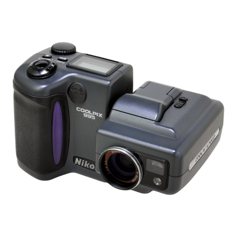
Nikon coolpix7900 Operating instructions

作成承認印 配布許可印
Copyright c 2005 by Nikon Corporation.
All Rights Reserved.
無断転載を禁ず
!!
Printed in Japan March 2005
VAA46003-R.3659.A
REPAIR MANUAL
VAA46003

VAA46003-R.3659.A
- E7900 -
CONTENTS
SPECIFICATIONS ・・・・・・・・・・・・・・・・・・・・・・・・・・・・・・・・・・・・・・・・・・・・・・・・・・・・・・・・・・・・・・・・・・・・・・・・・ M1-M2
Disassembly ・・・・・・・・・・・・・・・・・・・・・・・・・・・・・・・・・・・・・・・・・・・・・・・・・・・・・・・・・・・・・・・・・・・・・・・・・・・・・・・・・・・・ D1
WARNING・・・・・・・・・・・・・・・・・・・・・・・・・・・・・・・・・・・・・・・・・・・・・・・・・・・・・・・・・・・・・・・・・・・・・・・・・・・・・・・・・・ D1
Removal of rear cover ・・・・・・・・・・・・・・・・・・・・・・・・・・・・・・・・・・・・・・・・・・・・・・・・・・・・・・・・・・・・・・・・・・・ D2-D3
Disassembly of rear cover ・・・・・・・・・・・・・・・・・・・・・・・・・・・・・・・・・・・・・・・・・・・・・・・・・・・・・・・・・・・・・・・・・・・・・・ D4
Front cover ・・・・・・・・・・・・・・・・・・・・・・・・・・・・・・・・・・・・・・・・・・・・・・・・・・・・・・・・・・・・・・・・・・・・・・・・・・・・ D5-D6
Discharging of main condenser ・・・・・・・・・・・・・・・・・・・・・・・・・・・・・・・・・・・・・・・・・・・・・・・・・・・・・・・・・・・・・・・・・・ D7
RELEASE SWITCH UNIT ・・・・・・・・・・・・・・・・・・・・・・・・・・・・・・・・・・・・・・・・・・・・・・・・・・・・・・・・・・・・・・・・・・・・・ D7
Top FPC ・・・・・・・・・・・・・・・・・・・・・・・・・・・・・・・・・・・・・・・・・・・・・・・・・・・・・・・・・・・・・・・・・・・・・・・・・・・・・・・・・・・・ D8
LCD ・・・・・・・・・・・・・・・・・・・・・・・・・・・・・・・・・・・・・・・・・・・・・・・・・・・・・・・・・・・・・・・・・・・・・・・・・・・・・・・・・・・・・・・ D9
SB PCB ・・・・・・・・・・・・・・・・・・・・・・・・・・・・・・・・・・・・・・・・・・・・・・・・・・・・・・・・・・・・・・・・・・・・・・・・・・・・・・・・・・ D10
DC/DC PCB・・・・・・・・・・・・・・・・・・・・・・・・・・・・・・・・・・・・・・・・・・・・・・・・・・・・・・・・・・・・・・・・・・・・・・・・・・・・・・・ D11
Main PCB・・・・・・・・・・・・・・・・・・・・・・・・・・・・・・・・・・・・・・・・・・・・・・・・・・・・・・・・・・・・・・・・・・・・・・・・・・・・・・・・・ D11
Lens barrel unit ・・・・・・・・・・・・・・・・・・・・・・・・・・・・・・・・・・・・・・・・・・・・・・・・・・・・・・・・・・・・・・・・・・・・・・・・・・・・ D12
Disassembly of battery chamber ・・・・・・・・・・・・・・・・・・・・・・・・・・・・・・・・・・・・・・・・・・・・・・・・・・・・・・・・・・・・・・・ D12
CCD ・・・・・・・・・・・・・・・・・・・・・・・・・・・・・・・・・・・・・・・・・・・・・・・・・・・・・・・・・・・・・・・・・・・・・・・・・・・・・・・・・・・・・ D13
FINDER UNIT・・・・・・・・・・・・・・・・・・・・・・・・・・・・・・・・・・・・・・・・・・・・・・・・・・・・・・・・・・・・・・・・・・・・・・・・・・・・・ D13
Points to notice when disassembling/assembling Lens unit ・・・・・・・・・・・・・・・・・・・・・・・・・・・・・・・・・・・・・・・・・・ D14
Front lens group barrel unit ・・・・・・・・・・・・・・・・・・・・・・・・・・・・・・・・・・・・・・・・・・・・・・・・・・・・・・・・・・・・・・・・・・・ D14
Barrier unit ・・・・・・・・・・・・・・・・・・・・・・・・・・・・・・・・・・・・・・・・・・・・・・・・・・・・・・・・・・・・・・・・・・・・・・・・ D15-D16
Barrier turn plate ・・・・・・・・・・・・・・・・・・・・・・・・・・・・・・・・・・・・・・・・・・・・・・・・・・・・・・・・・・・・・・・・・・・ D16-D17
1st lens group unit ・・・・・・・・・・・・・・・・・・・・・・・・・・・・・・・・・・・・・・・・・・・・・・・・・・・・・・・・・・・・・・・・・・ D17-D18
1st unit ・・・・・・・・・・・・・・・・・・・・・・・・・・・・・・・・・・・・・・・・・・・・・・・・・・・・・・・・・・・・・・・・・・・・・・・・・・・・・・・・・・・ D18
Tension spring ・・・・・・・・・・・・・・・・・・・・・・・・・・・・・・・・・・・・・・・・・・・・・・・・・・・・・・・・・・・・・・・・・・・・・・・・・・・・・ D19
Fixed barrel ・・・・・・・・・・・・・・・・・・・・・・・・・・・・・・・・・・・・・・・・・・・・・・・・・・・・・・・・・・・・・・・・・・・・・・・・・・・・・・・ D20
Cam barrel ・・・・・・・・・・・・・・・・・・・・・・・・・・・・・・・・・・・・・・・・・・・・・・・・・・・・・・・・・・・・・・・・・・・・・・・・・・・・・・・・ D20
Straight barrel unit ・・・・・・・・・・・・・・・・・・・・・・・・・・・・・・・・・・・・・・・・・・・・・・・・・・・・・・・・・・・・・・・・・・・・・・・・・・ D21
Shutter unit・・・・・・・・・・・・・・・・・・・・・・・・・・・・・・・・・・・・・・・・・・・・・・・・・・・・・・・・・・・・・・・・・・・・・・・・ D22-D24
Cover ring unit ・・・・・・・・・・・・・・・・・・・・・・・・・・・・・・・・・・・・・・・・・・・・・・・・・・・・・・・・・・・・・・・・・・・・・・・・・・・・・ D24
CCD mount unit ・・・・・・・・・・・・・・・・・・・・・・・・・・・・・・・・・・・・・・・・・・・・・・・・・・・・・・・・・・・・・・・・・・・・・・・・・・・・ D25
Assembly・・・・・・・・・・・・・・・・・・・・・・・・・・・・・・・・・・・・・・・・・・・・・・・・・・・・・・・・・・・・・・・・・・・・・・・・・・・・・・・・・・・・・・・ A1
CCD mount unit ・・・・・・・・・・・・・・・・・・・・・・・・・・・・・・・・・・・・・・・・・・・・・・・・・・・・・・・・・・・・・・・・・・・・・・・・・・・・・・ A1
3rd lens group unit ・・・・・・・・・・・・・・・・・・・・・・・・・・・・・・・・・・・・・・・・・・・・・・・・・・・・・・・・・・・・・・・・・・・・・・・・・・・・ A2
Cover ring unit ・・・・・・・・・・・・・・・・・・・・・・・・・・・・・・・・・・・・・・・・・・・・・・・・・・・・・・・・・・・・・・・・・・・・・・・・・・・・・・・ A3
Shutter unit・・・・・・・・・・・・・・・・・・・・・・・・・・・・・・・・・・・・・・・・・・・・・・・・・・・・・・・・・・・・・・・・・・・・・・・・・・・・ A3-A5
Straight barrel・・・・・・・・・・・・・・・・・・・・・・・・・・・・・・・・・・・・・・・・・・・・・・・・・・・・・・・・・・・・・・・・・・・・・・・・・・・・・・・・ A6
Cam barrel ・・・・・・・・・・・・・・・・・・・・・・・・・・・・・・・・・・・・・・・・・・・・・・・・・・・・・・・・・・・・・・・・・・・・・・・・・・・・・・・・・・ A7

VAA46003-R.3659.A
- E7900 -
Fixed barrel ・・・・・・・・・・・・・・・・・・・・・・・・・・・・・・・・・・・・・・・・・・・・・・・・・・・・・・・・・・・・・・・・・・・・・・・・・・・・・・・・・ A7
Spring rack ・・・・・・・・・・・・・・・・・・・・・・・・・・・・・・・・・・・・・・・・・・・・・・・・・・・・・・・・・・・・・・・・・・・・・・・・・・・・・・・・・・ A8
1st lens group unit ・・・・・・・・・・・・・・・・・・・・・・・・・・・・・・・・・・・・・・・・・・・・・・・・・・・・・・・・・・・・・・・・・・・・・・・・・・・・ A9
Barrier turn plate ・・・・・・・・・・・・・・・・・・・・・・・・・・・・・・・・・・・・・・・・・・・・・・・・・・・・・・・・・・・・・・・・・・・・・・・・・・・ A10
Blade opening spring ・・・・・・・・・・・・・・・・・・・・・・・・・・・・・・・・・・・・・・・・・・・・・・・・・・・・・・・・・・・・・・・・・・・・・・・・ A10
Barrier unit ・・・・・・・・・・・・・・・・・・・・・・・・・・・・・・・・・・・・・・・・・・・・・・・・・・・・・・・・・・・・・・・・・・・・・・・・・・・・・・・・ A11
Barrier cover ring ・・・・・・・・・・・・・・・・・・・・・・・・・・・・・・・・・・・・・・・・・・・・・・・・・・・・・・・・・・・・・・・・・・・ A11-A12
Knurled gear・・・・・・・・・・・・・・・・・・・・・・・・・・・・・・・・・・・・・・・・・・・・・・・・・・・・・・・・・・・・・・・・・・・・・・・・・・・・・・・ A13
Front lens group barrel unit/CCD mount unit ・・・・・・・・・・・・・・・・・・・・・・・・・・・・・・・・・・・・・・・・・・・・・ A14-A15
FFD Inspection and adjustment (*FFD:Flange Focal Distance)(*Distance)・・・・・・・・・・・・・・・・・・・・・・・・・・・・・・ A16
Preparation・・・・・・・・・・・・・・・・・・・・・・・・・・・・・・・・・・・・・・・・・・・・・・・・・・・・・・・・・・・・・・・・・・・・・・・・・・・・・・ A16
FFD inspection and adjustment ・・・・・・・・・・・・・・・・・・・・・・・・・・・・・・・・・・・・・・・・・・・・・・・・・・・・・・ A16-A18
FFD adjustment ・・・・・・・・・・・・・・・・・・・・・・・・・・・・・・・・・・・・・・・・・・・・・・・・・・・・・・・・・・・・・・・・・・・・・・・・・・ A19
"How to calculate ""washer amount"" for the FFD adjustment"・・・・・・・・・・・・・・・・・・・・・・・・・・・・・・・・・・・・・ A19
Resolution inspections ・・・・・・・・・・・・・・・・・・・・・・・・・・・・・・・・・・・・・・・・・・・・・・・・・・・・・・・・・・・・・・・・・・・・・・・ A20
CCD ・・・・・・・・・・・・・・・・・・・・・・・・・・・・・・・・・・・・・・・・・・・・・・・・・・・・・・・・・・・・・・・・・・・・・・・・・・・・・・・・・・・・・ A21
FINDER UNIT・・・・・・・・・・・・・・・・・・・・・・・・・・・・・・・・・・・・・・・・・・・・・・・・・・・・・・・・・・・・・・・・・・・・・・・・・・・・・ A22
Assembly of battery chamber・・・・・・・・・・・・・・・・・・・・・・・・・・・・・・・・・・・・・・・・・・・・・・・・・・・・・・・・・・・・・・・・・・ A23
Lens barrel unit ・・・・・・・・・・・・・・・・・・・・・・・・・・・・・・・・・・・・・・・・・・・・・・・・・・・・・・・・・・・・・・・・・・・・・・・・・・・・ A24
Main PCB・・・・・・・・・・・・・・・・・・・・・・・・・・・・・・・・・・・・・・・・・・・・・・・・・・・・・・・・・・・・・・・・・・・・・・・・・・・・・・・・・ A24
DC/DC PCB・・・・・・・・・・・・・・・・・・・・・・・・・・・・・・・・・・・・・・・・・・・・・・・・・・・・・・・・・・・・・・・・・・・・・・・・・・・・・・・ A25
SB PCB ・・・・・・・・・・・・・・・・・・・・・・・・・・・・・・・・・・・・・・・・・・・・・・・・・・・・・・・・・・・・・・・・・・・・・・・・・・・・・・・・・・ A26
LCD ・・・・・・・・・・・・・・・・・・・・・・・・・・・・・・・・・・・・・・・・・・・・・・・・・・・・・・・・・・・・・・・・・・・・・・・・・・・・・・・・・・・・・ A27
Top FPC ・・・・・・・・・・・・・・・・・・・・・・・・・・・・・・・・・・・・・・・・・・・・・・・・・・・・・・・・・・・・・・・・・・・・・・・・・・・・・・・・・・ A28
RELEASE SWITCH UNIT ・・・・・・・・・・・・・・・・・・・・・・・・・・・・・・・・・・・・・・・・・・・・・・・・・・・・・・・・・・・・・・・・・・・ A29
Front cover ・・・・・・・・・・・・・・・・・・・・・・・・・・・・・・・・・・・・・・・・・・・・・・・・・・・・・・・・・・・・・・・・・・・・・・・・ A30-A31
Assembly of rear cover・・・・・・・・・・・・・・・・・・・・・・・・・・・・・・・・・・・・・・・・・・・・・・・・・・・・・・・・・・・・・・・・・・・・・・・ A32
Installation of rear cover ・・・・・・・・・・・・・・・・・・・・・・・・・・・・・・・・・・・・・・・・・・・・・・・・・・・・・・・・・・・・・ A33-A34
ADJUSTMENT ・・・・・・・・・・・・・・・・・・・・・・・・・・・・・・・・・・・・・・・・・・・・・・・・・・・・・・・・・・・・・・・・・・・・・・・ A35-A45
DISCRIPTION OF CIRCUIT・・・・・・・・・・・・・・・・・・・・・・・・・・・・・・・・・・・・・・・・・・・・・・・・・・・・・・・・・・・・・・・・・ E1-E7
ELECTRICTIY・・・・・・・・・・・・・・・・・・・・・・・・・・・・・・・・・・・・・・・・・・・・・・・・・・・・・・・・・・・・・・・・・・・・・・・・・・・・・・・・・・ E8
OVERALL WIRING ・・・・・・・・・・・・・・・・・・・・・・・・・・・・・・・・・・・・・・・・・・・・・・・・・・・・・・・・・・・・・・・・・・・・・・・・・・ E8
CP1(DMA) CIRCUIT DIAGRAM ・・・・・・・・・・・・・・・・・・・・・・・・・・・・・・・・・・・・・・・・・・・・・・・・・・・・・・・・・・・・・・・ E9
CP1(SYA) CIRCUIT DIAGRAM ・・・・・・・・・・・・・・・・・・・・・・・・・・・・・・・・・・・・・・・・・・・・・・・・・・・・・・・・・・・・・・ E10
CP1(CAA) CIRCUIT DIAGRAM・・・・・・・・・・・・・・・・・・・・・・・・・・・・・・・・・・・・・・・・・・・・・・・・・・・・・・・・・・・・・・ E11
CP1(VFA) CIRCUIT DIAGRAM ・・・・・・・・・・・・・・・・・・・・・・・・・・・・・・・・・・・・・・・・・・・・・・・・・・・・・・・・・・・・・・ E12
CP1 (CAB) CIRCUIT DIAGRAM ・・・・・・・・・・・・・・・・・・・・・・・・・・・・・・・・・・・・・・・・・・・・・・・・・・・・・・・・・・・・・ E13
PW1 CIRCUIT DIAGRAM・・・・・・・・・・・・・・・・・・・・・・・・・・・・・・・・・・・・・・・・・・・・・・・・・・・・・・・・・・・・・・・・・・・ E14
VAA46003-R.3659.A
- E7900 -
OVERALL BLOCK DIAGRAM・・・・・・・・・・・・・・・・・・・・・・・・・・・・・・・・・・・・・・・・・・・・・・・・・・・・・・・・・・・・・・・ E15
CCD BLOCK DIAGRAM ・・・・・・・・・・・・・・・・・・・・・・・・・・・・・・・・・・・・・・・・・・・・・・・・・・・・・・・・・・・・・・・・・・・・ E16
LENS BLOCK DIAGRAM ・・・・・・・・・・・・・・・・・・・・・・・・・・・・・・・・・・・・・・・・・・・・・・・・・・・・・・・・・・・・・・・・・・・ E17
ASIC BLOCK DIAGRAM ・・・・・・・・・・・・・・・・・・・・・・・・・・・・・・・・・・・・・・・・・・・・・・・・・・・・・・・・・・・・・・・・・・・ E18
SYSTEM CONTROL BLOCK DIAGRAM ・・・・・・・・・・・・・・・・・・・・・・・・・・・・・・・・・・・・・・・・・・・・・・・・・・・・・・ E19
POWER BLOCK DIAGRAM ・・・・・・・・・・・・・・・・・・・・・・・・・・・・・・・・・・・・・・・・・・・・・・・・・・・・・・・・・・・・・・・・・ E20
FUSE conguration (PW1 PCB) ・・・・・・・・・・・・・・・・・・・・・・・・・・・・・・・・・・・・・・・・・・・・・・・・・・・・・・・・・・・・・・・ E21
INSPECTION STANDARDS・・・・・・・・・・・・・・・・・・・・・・・・・・・・・・・・・・・・・・・・・・・・・・・・・・・・・・・・・・・・・・・・・ R1-R8
TOOL LIST ・・・・・・・・・・・・・・・・・・・・・・・・・・・・・・・・・・・・・・・・・・・・・・・・・・・・・・・・・・・・・・・・・・・・・・・・・・・・・・ T1-T5

VAA46003-R.3659.A
- M1・ E7900 -
Type E7900 digital camera
Effective pixels
CCD
Image size (pixels)
7.1 million
1/1.8” high-density CCD; total pixels: 7.41 million
・ 3,072 ×2,304 [7M] ・ 2,592 ×1,944 [5M] ・ 2,048 ×1,536 [3M]
・ 1,024 ×768 [PC] ・ 640 ×480 [TV]
Lens
Focal length
f/-number
Construction
3× Zoom-Nikkor ED lens
F=7.8 - 23.4 mm (35-mm [135] camera-format equivalent:38 - 114 mm)
f/2.8 - f/4.9
Seven elements in six groups (includes 1 glass-molded EDlens elements)
Digital zoom Up to 4× (35-mm [135] camera-format equivalent: 450 mm)
Autofocus (AF)
Focus range
Focus area selection
AF-assist illuminator
Contrast-detect through-the-lens (TTL) AF, AF-assist illuminator
30 cm (1') - ; macro mode 4 cm/1.6” (W) - ∞
Auto (five-area automatic selection), Manual (99-area manual selection), Off (center
focus area selection)
CLASS 1 LED PRODUCT (IEC60825-1 Edition 1.2-2001)
Maximum output: 1700 μW
Viewfinder
Magnification
Frame coverage
Real-image zoom viewfinder with LED indication
0.31 - 0.77 ×
Approximately 75% holizontal and 75% vertical
Monitor
Frame coverage
(shooting mode)
2.0”, 115,000-dot, amorphous silicon TFT transflective LCD with brightness
adjustment
Approximately 100% horizontal and 100% vertical
Storage
Media
File system
File formats
Internal memory (approximately 13.5MB)/SD (Secure Digital) Memory cards
Compliant with Design Rule for Camera File System (DCF), Exif 2.2, and Digital
Print Order Format (DPOF)
Compressed: JPEG-baseline-compliant (1:4, 1:8, 1:16)
Movies: Quick Time Sound files: WAV
Exposure
Metering
Exposure control
Range
Four mode through-the-lens (TTL) metering;
・ 256-segment matrix ・ Spot ・ Center-weighted ・ Spot AF area
Programmed auto exposure with exposure compensation
(-2.0 - +2.0EV in steps of 1/3EV), Auto bracketing
W: +1 - +16.5EV
T: +2.6 - +18.1EV
(Sensitivity: Auto)
SPECIFICATIONS

VAA46003-R.3659.A
- M2・ E7900 -
Shutter
Speed
Mechanical and charge-coupled electronic shutter
4 - 1/2,000s
Aperture
Range
Electronically-controlled preset aperture
Two steps (f/2.8 and f/4.8 [W])
Sensitivity Approximately equivalent to ISO 50, 100, 200, 400; Auto
(auto gain to ISO 200 equivalent)
Self-timer Ten-second, three-second duration
Built-in Speedlight
Range (approx.)
Flash control
0.3 - 4.5 m/1’ - 14’8” (W)
0.3 - 3.5 m/1’ - 11’5” (T)
(Sensitivity: Auto)
Sensor flash system
Interface USB
Video output Can be selected from NTSC and PAL
I/O terminals DC in; Digital I/O (audio-visual out and USB)
Supported language Chinese (Simplified and Traditional), Dutch, English,
French, German, Italian, Japanese, Korean, Spanish, Swedish
Power sources・ One rechargeable Nikon EN-EL5 (Rechargeable lithiumion battery; supplied)
・ One CP1 lithium battery ・ EH-62A AC adapter kit (available separately)
Approximate battery life Approximately 220 shots (EN-EL5)/250 shots (CP1)
Based on CIPA standard*
Dimensions
(W ×H×D)
Approximately 88 ×60 ×36.5 mm/3.46”×2.4”×1.44”
(excluding projection parts)
Approximate weight 150 g (5.3 oz) without battery or memory card
Operating environment
Temperature
Humidity
0 - 40°C (32 - 104°F)
Less than 85% (no condensation)
* Industry standard for measuring life of camera batteries. Measured at 25 °C (77 °F); zoom adjusted with each shot,
built-in Speedlight red with every other shot, image mode set to NORM/ .

VAA46003-R.3659.A
- D1・ E7900 -
Disassembly
Note : ① Be sure to remove the SD memory card and batteries before disassembly.
② When disassembling, make sure to memorize the processing state of wires, screws
to be xed and their types, etc.
③ Because electrical parts are easily damaged by static electricity, make sure that you
are well earthed/grounded.
Points to notice for Lead-free solder products
・Lead-free solder is used for this product.
・For soldering work, the special solder and soldering iron are required.
・Do NOT mix up lead-free solder with traditional solder.
・Use the special soldering iron respectively for lead-free solder and lead solder. They
cannot be used in common.

VAA46003-R.3659.A
- D2・ E7900 -
Removal of rear cover
・ Remove the two screws (811).
1. Removal of screws
・ Remove the two screws (810).
・ Remove the two screws (809).
Screws (811)
Screws (810)
Screws (809)

VAA46003-R.3659.A
- D3・ E7900 -
2. Removal of rear cover
・ Open the SD case (B351) and the battery case (B341).
・ Open the bottom of the rear cover and then the top of it. (Be careful because the FPC connected with the rear cover is
attached to the body.)
・ Pull out the FPC.
・ Remove the connector.
・ The rear cover can be removed.
SD case (B351)
Battery case (B341)
Bottom of rear cover
FPC
Rear cover
Connector

VAA46003-R.3659.A
- D4・ E7900 -
Disassembly of rear cover
・ Take off the rear FPC insulating seal (719).
・ Remove the six screws (819).
・ The rear SW unit (1018) can be removed.
・ The determining button spring (245) can be removed.
・ The speaker (1025) can be removed.
・ Remove the determining button (241).
・ Remove the switch rubber (244).
・ The multi-selector (242) can be removed.
Speaker (1025)
Switch rubber (244)
Determining button (241)
Multi-selector (242)
Rear FPC insulating seal (719)
Screws (819)
Screws (819)
Determining button spring (245)
Rear SW unit (1018)

VAA46003-R.3659.A
- D5・ E7900 -
Front cover
・ Close the SD case (B351).
・ Remove the strap (126).
・ The battery cord cover (362) can be removed.
1. Removal of strap (at grip side)
・ As pulling the strap (125) toward your side, lift its top and
remove it.
・ The USB cover (361) can be removed.
2. Removal of strap (at the battery cord cover side)
・ Remove the two screws (810).
・ Remove the tripod socket (B371).
3. Removal of tripod socket
Strap (126)
SD case (B351)
Battery cord cover (362)
USB cover (361)
Strap (125)
Screws (810)
Tripod socket (B371)

VAA46003-R.3659.A
- D6・ E7900 -
+
+
VR501
F5002
F5001F5004
2A
2A
F5005
2A
2A
SIDE-B
+
T
-
-
+
SWQ14_PW1
F3300AA
RD
BK
L5009 L5010
F5005
Q5001
C5028
C5029
C5032
IC501
L5005
L5006
L5007
L5004
L9601
C9601
C9602
D9601
C9603
D5001
L5001
L5002
C5031 C5033
Q9601
IC961
C5022
D5003
D5004
C5023
D5006
C5016
Q5002
C5025
Q5003
F5001
VR501
R5009
Q9602 Q5007
F5004
R5043
R9607
R9606
R9604
C9604
R5036
R5032
R5035
R5033
R5034
C5009
C5030
R5201
F5002
R5004
R5002
R5006
C5024
L5003
Q5004
D5007
T5001
C5035
R5046
C5037
C5036
VA502
F5005
F5002
F5001 、F5004
・ Remove the two screws (808).
4. Removal of front cover/fixed barrel curtain
・ Remove the two screws (811).
・ Remove the front cover.
・ The fixed barrel curtain (618) can be removed.
Screws (808)Screws (811)
Fixed barrel curtain (618)
・ Under this condition, it is possible to replace fuses of F5001,
F5002, F5004 and F5005 with new ones.

VAA46003-R.3659.A
- D7・ E7900 -
・ Remove the strap (124).
・ Turn up the tape and remove the FPC.
・ Remove the release SW unit (1016).
Discharging of main condenser
2KΩ/5W
Main condenser
Cord arranging tape (715)
RELEASE SWITCH UNIT
FPC
Release SW unit (1016)Strap (124)
Tape

VAA46003-R.3659.A
- D8・ E7900 -
FPC (A)
・ Take off the FPC(A) from the double adhesive tape.
・ Remove the two screws (812).
・ Remove the screw (801).
・ Remove the FPC(B) from the connector
・ Remove the top FPC.
Top FPC
FPC (B)
Screws (812)
Screw (801)
Top FPC

VAA46003-R.3659.A
- D9・ E7900 -
LCD
・ Remove the three screws (815).
・ Lift up the LCD. Then, remove the FPC, the connector and the LCD.
・ Remove the lug plates (394).
・ Remove the chassis (152).
(Fig.1)
Screws (815)
Screws (815)
Lug plates (394)
LCD
FPC
LCD
Chassis (152)
Connector

VAA46003-R.3659.A
- D10 ・ E7900 -
SB PCB
・ Take off the two cord arranging tapes (717).
・ Remove the one cord arranging tape (716).
・ Remove the lead wire [black] and the lead wire [red].
1. Removal of cords/tapes
・ Remove the SB control harness (1013) from the connector.
2. Removal of harness
・ Remove the condenser.
・ Remove the connector (Fig. 1) and then remove the microphone (1023).
・ Take off the SB insulating sheet (711).
・ Remove the two screws (804).
・ The SB PCB can be removed.
3. Removal of condenser/microphone/SB PCB
Cord arranging tapes (717)
Cord arranging tape (716)
Cord arranging tapes (717)
Microphone (1023)
Lead wires [black] and [red]
(Fig.1)
SB control harness (1013)
Connector
Condenser
Cord arranging tape (716)
Screws (804)
SB insulating sheet (711)
SB PCB
Microphone (1023)
Screws (804)

VAA46003-R.3659.A
- D11 ・ E7900 -
DC/DC PCB
・ Remove the solder of the armature.
・ Remove the two screws (816).
・ Remove the DC/DC PCB from the main PCB connector.
・ The strap eyelet (381) can be removed.
Armature
Screws (816)
Strap eyelet (381)
DC/DC PCB
Position of the main PCB connector (Rear surface)
Main PCB
・ Remove the FPC.
・ Perform unsoldering.
・ Remove the screw (803).
・ Remove the two screws (818).
・ Remove the lug plate (392).
・ Remove the main PCB (B1001).
・ Remove the lug plate (397). FPC
Screw (803)
Screws (818)
Lug plate (397)
Lug plate (392)
Main PCB (B1001)
はんだ

VAA46003-R.3659.A
- D12 ・ E7900 -
Disassembly of battery chamber
・ Remove the two screws (802)
・ Unlock the SD case unit (B351) and then remove the SD case unit (B351).
・ Remove the lug plate (395).
・ Remove the two screws (802)
・ Unlock the battery case unit (B341) and then remove the battery case (B341).
・ The battery spring (350) can be removed.
Lens barrel unit
・ Remove the two screws (803).
・ Remove the two screws (801).
・ The chassis (151) can be removed.
・ The battery chamber unit (B10345) can be removed.
Screws (803)
Chassis (151)
Screws (801)
Screws (803)
Battery chamber unit (B10345)
Screws (802)
SD case unit (B351)
Lug plate (395)
Battery spring (350)
Battery case (B341)
Screws (802)
Battery chamber

VAA46003-R.3659.A
- D13 ・ E7900 -
CCD
FINDER UNIT
・ Remove the Light-shiled sponge (741).
・ Remove the two screws (813).
・ Remove the CCD PCB.
・ The CCD rubber (609) can be removed.
・ The LPF (8) can be removed.
・ The LPF mask (624) can be removed.
・ Remove the three screws (815).
・ The finder unit (B501) can be removed.
Light-shiled sponge (741)
Screws (813)
CCD rubber (609)
LPF (8)
LPF mask (624)
CCD PCB
Screws (815)
Finder unit (B501)

VAA46003-R.3659.A
- D14 ・ E7900 -
Points to notice when disassembling/assembling Lens unit
When the following parts are replaced for repairing the lens unit, the lens unit checking tool is required for the
FFD inspection and adjustment. Therefore, at service facilities where there is no tool, do NOT make a replace-
ment
・1st lens group (B601)
・2nd lens group
(6B999-112)
・3rd lens group(B603)
・CCD stand unit(6B999-113)
When the operation check and adjustment of the lens unit are made for repairing the lens unit,the following
tools are required.
・Lens unit checking tool : J61202
・Connection cable for lens : J61202E
・PCI I/F board :
J61204
・Connection cable for PC : J61204A
・Adjusting focus stand for APS : J15327
・Adapter for J15327 :
J15327A
・Adapter for J15327 E4200/E5200 : J15327B
・E5200/E4200 lens unit checking program : J65067
Table of contents
Other Nikon Digital Camera manuals

Nikon
Nikon Coolpix L12 User manual

Nikon
Nikon D5100 User manual

Nikon
Nikon CoolPix S6000 User manual

Nikon
Nikon D2X Operating instructions

Nikon
Nikon 26213 User manual

Nikon
Nikon D3100 VBA28001 Operating instructions

Nikon
Nikon Coolpix S220 Parts list manual

Nikon
Nikon CoolPix S4300 User manual

Nikon
Nikon F5 - F 5 SLR Camera User manual

Nikon
Nikon Coolpix S630 User manual

Nikon
Nikon Z 7 Quick start guide

Nikon
Nikon COOLPIX S2700 User manual

Nikon
Nikon D60 User manual

Nikon
Nikon CoolPix 800 User manual

Nikon
Nikon CoolPix S700 User guide

Nikon
Nikon Coolpix S6600 User manual

Nikon
Nikon 25452 User manual

Nikon
Nikon CoolPix P7700 User manual

Nikon
Nikon Fun >Touch 4 User manual

Nikon
Nikon CoolPix 3200 User manual