SolaX Power G2 User manual

品名
材料
料号
单位 页次
设计
审核
核准
320101064101 浙江艾罗网络能源技术股份有限公司
NA
REV. REV.
Description Description
0.0
品名
料号
单位
320101064101
页次
浙江艾罗网络能源技术股份有限公司
SolaX Power Network Technology (Zhejiang) Co., Ltd.
技术要求:
1.封面封底157g铜版纸覆哑膜彩打,内部纸80g双胶纸黑白印刷,正反打印
2.装订方式:页码大于60需用胶装
3.未注尺寸公差按 +- 1.5mm
4.图面、字体印刷清晰、无毛边、不起边、油墨不脱落
5.字体颜色为PANTONE Black C,无边框,底色为白色
6.符合RoHS要求
赵焱
施鑫淼
郑安琪 2023/10/26
210 mm
143mm
User Manual
说明书 BMS Parallel Box-Ⅱ G2 英文版 SolaX 01版
2023/10/26
2023/10/26
说明书 BMS Parallel Box-Ⅱ G2 英文版 SolaX 01版
Triple Power BMS Parallel Box- G2
EN
Ⅱ
修改所有涉及并联盒外观及端口细节的示意
图,连接T30&T58及逆变器的接线示意图。
修改丝印CAN为M-CAN/S-CAN。
0.1
郑安琪 2023/10/26
郑安琪 2023/09/20
首次发布

Triple Power BMS Parallel Box- G2
User Manual
Copyright © SolaX Power Technology (Zhejiang) Co., Ltd. All rights reserved.
No part of this document may be reproduced or transmitted in any form or by any
means without prior written consent of SolaX Power Technology (Zhejiang) Co., Ltd.
(hereinafter referred to as SolaX). SolaX reserves the right of final interpretation.
320101064101
SolaX Power Network Technology (Zhejiang) Co., Ltd.
Add.: No. 288, Shizhu Road, Tonglu Economic Development Zone, Tonglu City,
Zhejiang Province, 310000 P.R. CHINA
Tel.: +86 (0) 571-5626 0011
E-mail: info@solaxpower.com
EN
Ⅱ

CHANGE HISTORY
Changes between document versions are cumulative. The latest version
contains all updates made in previous versions.
Version 01 (Oct. 26, 2023)
Version 00 (Sept. 21, 2023)
Initial release
Updated all pictures that include the appearance and port details of
the parallel box.

Contents
1 NOTE ON THIS MANUAL
1.1 SCOPE OF VALIDITY..........................................................................................
1.2 TARGET GROUP...................................................................................................
1.3 SYMBOLS USED..................................................................................................
2 SAFETY................................................................................................................................
2.1 APPROPRIATE USAGE.......................................................................................
2.2 IMPORTANT SAFETY INSTRUCTIONS.........................................................
2.3 QUALIFIED INSTALLER......................................................................................
3 PRODUCT INTRODUCTION.......................................................................................
3.1 PRODUCT OVERVIEW......................................................................................
3.1.1 DIMENSIONS .........................................................................................................
3.1.2 APPEARANCE.......................................................................................................
3.2 BASIC FEATURES................................................................................................
3.2.1 FEATURES...............................................................................................................
3.2.2 CERTIFICATIONS.................................................................................................
3.3 TECHNICAL DATA...............................................................................................
4 INSTALLATION.................................................................................................................
4.1 INSTALLATION PREREQUISITES...................................................................
4.2 SAFETY GEAR......................................................................................................
4.3 TOOLS....................................................................................................................
4.4 INSTALLATION.....................................................................................................
4.4.1 CHECK FOR TRANSPORT DAMAGE...........................................................
4.4.2 UNPACKING...........................................................................................................
4.4.3 ACCESSORIES.....................................................................................................
4.4.4 MOUNTING STEPS.............................................................................................
.............................................................................................
OVERALL INSTALLATION................................................................................
14
4.5
1
1
1
1
2
2
3
11
11
11
12
12
4
6
6
6
7
8
8
9
10
10
10
11
8
1 NOTE ON THIS MANUAL..............................................................................1
1.1 SCOPE OF VALIDITY...............................................................................1
1.2 TARGET GROUP......................................................................................1
1.3 SYMBOLS USED.......................................................................................1
2 SAFETY .....................................................................................................2
2.1 APPROPRIATE USAGE ...........................................................................2
2.2 IMPORTANT SAFETY INSTRUCTIONS................................................3
2.3 QUALIFIED INSTALLER ..........................................................................4
3 PRODUCTION INTRODUCTION ................................................................6
3.1 PRODUCTION OVERVIEW ...................................................................6
3.1.1 DIMENSIONS............................................................................6
3.1.2 APPEARANCE ...........................................................................7
3.2 BASIC FEATURES ....................................................................................8
3.2.1 FEATURES .................................................................................8
3.2.2 CERTIFICATIONS.....................................................................8
3.3 TECHNICAL DATA ..................................................................................8
4 INSTALLATION..............................................................................................10
4.1 INSTALLATION PREREQUISITES........................................................10
4.2 SAFETY GEAR ........................................................................................10
4.3 TOOLS ...................................................................................................11
4.4 INSTALLATION.......................................................................................11
4.4.1 CHECK FOR TRANSPORT DAMAGE..................................11
4.4.2 UNPACKING............................................................................11
4.4.3 ACCESSORIES ........................................................................12
4.4.4 MOUNTING STEPS................................................................12
4.5 OVERALL INSTALLATION ....................................................................14
4.6 CABLE CONNECTION.........................................................................16
4.6.1 CONNECTING CABLES TO INVERTER .............................16
4.6.2 CONNECTING BATTERY MODULES.................................18
4.6.3 CONNECTING COMMUNICATION CABLES...................20
5 COMMISSIONING ........................................................................................21
5.1 CONFIGURING BATTERY SYSTEM....................................................21
5.2 COMMISSIONING ................................................................................22
5.3 STATUS INDICATORS ..........................................................................23
6 TROUBLESHOOTING..................................................................................24
7 DECOMMISSIONING ..................................................................................26
7.1 DISMANTLING THE BOX ....................................................................26
7.2 PACKAGING ..........................................................................................26
8 MAINTENANCE.............................................................................................27
9 WARRANTY ..................................................................................................28
* WARRANTY REGISTRATION FORM
1 Note on this Manual
1.1 Scope of Validity
This manual is an integral part of the Parallel Box Series.
It describes the assembly, installation, commissioning, maintenance and
failure of the product. Please read carefully prior to operation.
Model:
1.2 Target Group
This manual is for qualified electricians. The tasks described in this manual
should only be performed by qualified electricians.
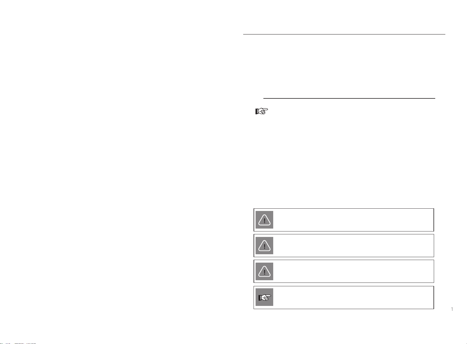
1.3 Symbols Used
The following types of safety instructions appear in this document are descri-
-bed below:
NOTE!
“NOTE” provides tips that are valuable for the optimal operation
of your product.
BMS Parallel Box- G2
The BMS Parallel Box- G2 can be used with T-BAT-SYS-HV-5.8 or T-BAT-SYS-
CAUTION!
“CAUTION” indicates a hazardous situation which, if not avoided,
could result in minor or moderate injury.
WARNING!
“WARNING” indicates a hazardous situation which, if not avoided,
could result in serious injury or death.
DANGER!
“DANGER” indicates a hazardous situation which, if not avoided,
will result in serious injury or death.
Notes on this Manual
HV-3.0. Please refer to section 4 “Installation ”from page 10 to page 20 for
NOTE!
details.
Ⅱ
Ⅱ

23
2 Safety
2.1 Appropriate Usage
For safety reasons, installers are responsible for familiarizing themselves with the
contents of this manual and all warnings before performing installation.
Safety Safety
2.2 Important Safety Instructions
CAUTION!
Danger of burn injuries due to hot enclosure parts!
During operation, the upper lid of the enclosure and the
enclosure body may become hot.
Only touch the lower enclosure lid during operation.
CAUTION!
Possible damage to health as a result of the effects of
WARNING!
Authorized service personnel must disconnect the cables
before attempting any maintenance or cleaning or work-
-ing on any circuits connected to the box.
Do not operate the parallel box when the device is
WARNING !
Risk of electric shock!
WARNING !
DANGER!
Danger to life due to high voltages in the parallel box!
All work must be carried out by qualified electrician.
The appliance is not to be used by children or persons
with reduced physical sensory or mental capabilities, or
lack of experience and knowledge, unless they have been
given supervision or instruction.
Children should be supervised to ensure that they do not
play with the appliance.
Do not stay closer than 0.66 ft/20 cm to the parallel box
radiation!
for any length of time.
running.
Ÿ
Ÿ
Ÿ
Ÿ
Ÿ
Ÿ
① Connect with T-BAT-SYS-HV-5.8
② Connect with T-BAT-SYS-HV-3.0
45
Prior to the application, please read this section carefully to ensure correct and
safe application.
Use only attachments recommended or sold by our company. Otherwise, it may
result in a risk of fire, electric shock, or injury to person.
Make sure that the existing wiring is in good condition and that the wire is not
Do not disassemble any parts of the box which are not mentioned in the user
manual. The parallel contains no user-serviceable parts.
yourself may result in a risk of electric shock or fire and will void your warranty.
Keep the parallel box away from flammable, explosive materials to avoid fire
The installation place should be away from humid or corrosive substance.
Authorized service personnel must use insulated tools when installing or working
with this equipment.
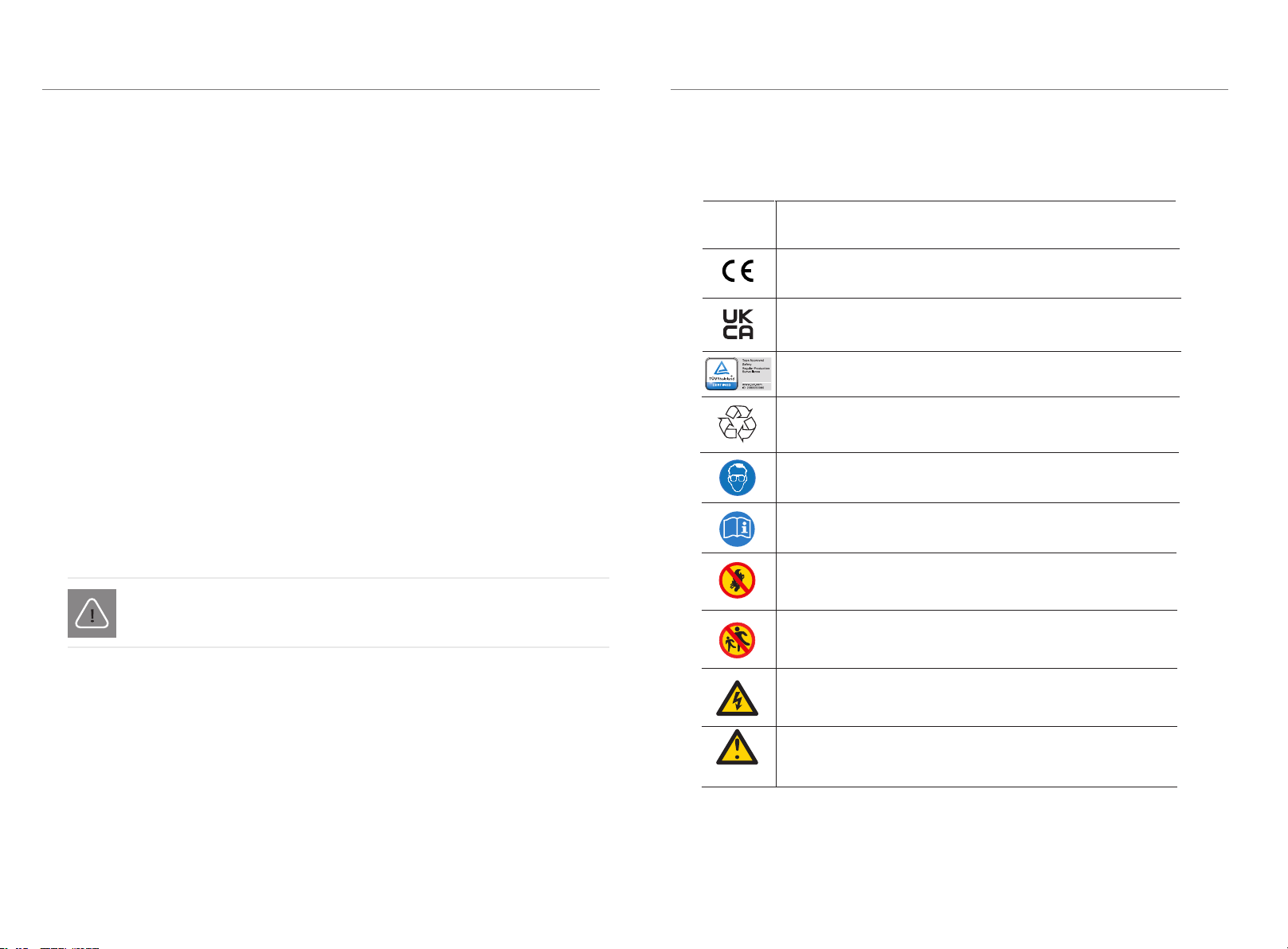
Explanation of Symbols
This section gives an explanation of all the symbols shown on the warning label.
Wear protective glasses.
Observe enclosed documentation.
Keep the battery system away from open flames or ignition
sources.
Symbol Explanation
The system must be disposed of at a proper facility for
environmentally-safe recycling.
The system should not be disposed of together with
household waste. Disposal information can be found in the
enclosed documentation.
Danger of high voltages.
Keep the battery system away from children.
Danger. Risk of electric shock.
2.3 Qualified Installer
A skilled worker is defined as a trained and qualified electrician or installer who
has all of the following skills and experience:
Knowledge of the functional principles and operation of grid-tied systems
Knowledge of the dangers and risks associated with installing and using
electrical devices and acceptable mitigation methods
Knowledge of the installation of electrical devices
Knowledge of and adherence to this manual and all safety precautions and
best practices
WARNING!
All operations of box relating to electrical connection and installation
must be carried out by qualified personnel.
TUV certification
Please keep the user manual properly.
Symbol Explanation
Keep the battery system away from open flames or ignition
sources.
Keep the battery system away from children.
Caution, risk of electric shock
Caution, risk of danger
Read the enclosed documentation.
TUV certification
undersized.
disaster.
2.4
See Warranty for instructions on obtaining service. Attempting to service the box
CE mark of conformity
UKCA mark of conformity
•
•
•
•
•
•
•
•
•
•
•
•
•
Safety
Safety
67
3 Product Introduction
3.1 Product Overview
For safety reasons, installers are responsible for familiarizing themselves with the
contents of this manual and all warnings before performing installation.
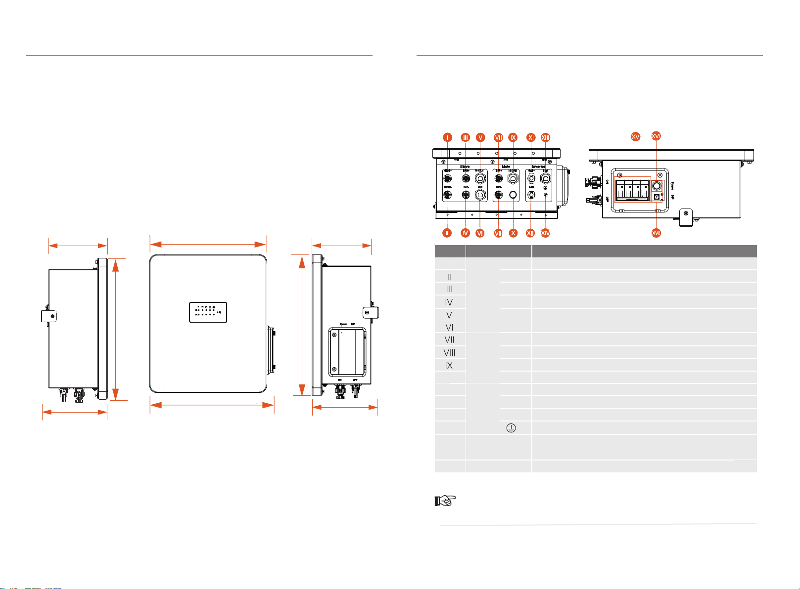
3.1.1 Dimension
Product Introduction
3.1.2 Appearance
ŸTerminals of the BMS Parallel Box-Ⅱ G2
13.15 in./334.00 mm
14.48 in./368.00 mm
12.28 in./312.00 mm
6.04 in.
153.50 mm
Object Mark Description
HEAT-
BAT-
CAN
BAT-
CAN
HEAT+
XI
X
XII
XIII
XIV
BAT+
485
BAT+
BAT+
BAT-
BMS
ON/OFF
POWER
Circuit Breaker
Power Button
DIP DIP Switch
XV
XVI
XVII
Bottom view: Right side view:
The cable connection between the BMS Parallel Box-Ⅱ G2 and T-BAT-SYS-HV-5.8
is different from that between the BMS Parallel Box-Ⅱ G2 and T-BAT-SYS-HV-3.0.
/
Connector "Heat+" of the parallel box to "Heat+" of Slave
Connector "Heat-" of the parallel box to "Heat-" of Slave
Connector "BAT+" of the parallel box to "B+"/"+" of Slave
Battery module communication of Slave
Battery module communication of Slave
Connector "BAT+" of the parallel box to "BAT+" of Main
Connector "BAT-" of the parallel box to "BAT+" of Main
Connector "BAT-" of the parallel box to "BAT+" of Main
Air Venue
Connector "BAT+" of the parallel Box to "BAT+" of inverter
Connector "BAT-" of the parallel Box to "BAT-" of inverter
Connector "BMS" of the parallel Box to "BMS" of inverter
NOTE!
6.04 in.
153.50 mm
14.48 in./368.00 mm
GND
Slave
Main
Inverter
6.79 in.
172.50 mm
6.79 in.
172.50 mm
Connector "BAT-" of the parallel box to "B-"/"XPLUG" of Slave
Please refer to Section 4. Installation starting from page 10 for detailed information.
Product Introduction
I III V VII IX XI
XIII
S-

Product Introduction
9
Product Introduction
3.2 Basic Features
3.2.1 Features
The box has advanced technology, high reliability and convenient control functions,
Secondary protection by hardware
IP65 protection level
Safe and reliable
Small occupied area
Wall mounting
3.2.2 Certifications
Safety IEC 62477-1, IEC 61439-1, IEC 61439-2
3.3 Technical Data
Interact with inverter
According to the interactive information, judge and control the
running state of the battery system
BMS related control processing
Realize the corresponding fault identification and processing
Ensure the safe operation of the battery system.
Maximum Charge/Discharge Current (A)
35
Model
BMS Parallel Box-II G2
Dimension (W/H/D)(in/mm)
Dimension of Packing (W/H/D)(in/mm)
Net Weight (lbs/kg)
14.48*13.15*6.04/368*334*153.5
17.32*15.63*10.12/440*397*257
19.12/8.7
Overvoltage Category (OVC)
II
I
Protective Class
EMC IEC 61000-6-1/2/3/4
as shown below:
System one Nominal
voltage [V]
Operating
voltage [V]
Total capacity
[kWh]
Usable capacity
[kWh]
Nominal
power [kW]
Max power
[kW]
T-BAT S 5.8 G2
T-BAT S 11.5 G2
T-BAT S 17.3 G2
T-BAT S 23.0 G2
T-BAT P 5.8 G2
T-BAT P 11.5 G2
T-BAT P 17.3 G2
T-BAT P 23.0 G2
115.2
230.4
345.6
460.8
115.2
230.4
345.6
460.8
110-131
200-262
300-393
400-524
100-131
200-262
300-393
400-524
5.8
11.5
17.3
23.0
11.5
23.0
34.6
46.1
5.1
10.3
15.5
20.7
10.3
20.7
31.1
41.4
2.8
5.7
8.6
11.5
2.8
5.7
8.6
11.5
4.0
8.0
12.0
16.1
4.0
8.0
12.0
16.1
System two Nominal
voltage [V]
Operating
voltage [V]
Total capacity
[kWh]
Usable capacity
[kWh]
Nominal
power [kW]
Max power
[kW]
T-BAT S 3.0 G2
T-BAT S 6.0 G2
T-BAT S 9.0 G2
T-BAT S 12.0 G2
T-BAT P 3.0 G2
T-BAT P 6.0 G2
T-BAT P 9.0 G2
T-BAT P 12.0 G2
102.4
204.8
307.2
409.6
102.4
204.8
307.2
409.6
90-116
180-232
270-348
360-464
90-116
180-232
270-348
360-464
3.1
6.1
9.2
12.3
6.1
12.3
18.4
24.6
2.7
5.5
8.2
11.0
5.5
11.0
16.5
22.1
2.5
5.1
7.6
10.2
2.5
5.1
7.6
10.2
3.0
6.1
9.2
12.2
3.0
6.1
9.2
12.2
Input/Output voltage Range (V)
Standard Power (kW)
Maximum Power (kW)
70-550
11.5
16.1
Pollution Degree
Operating Temperature
Ingress Protection
PD 3
II
Environment Requirement
Outdoor
Altitude (ft/m)
≤ 6561.68/2000
Noise Level
<30dB
Environment
T-BAT-SYS-HV-3.0:
-30°C~55°C (with heating function)
-10°C~55°C (no heating function)
T-BAT-SYS-HV-5.8:
0°C ~ 55°C (no heating function)
P65
Recommend charge/discharge current [A]
25
8
(T-BAT-SYS-HV-3.0)
(T-BAT-SYS-HV-5.8)
•
•
•
•
•
•
•
•
•
•
10 11
4 Installation
4.1 Installation Prerequisites
When assembling the system, avoid touching the terminal with any metal objects
or bare hands. The box provides a safe source of electrical energy when operated
as designed.
The previous safety precautions and the warning messages described in this
section must be observed. If any of the previous precautions are not fully
understood, or if you have any questions, contact customer service for guidance.
The Safety Section may not include all regulations for your region.
Ensure that the installation location meets the following conditions:
The building is designed to withstand earthquakes
The floor is flat and level
No inflammable or explosive materials within a range of at least 3 ft/0.91 m.
The ambiance is shady and cool, away from heat and direct sunlight
The temperature and humidity remain at a constant level
There is minimal dust and dirt in the area
There are no corrosive gases present, including ammonia and acid vapor
4.2 Safety Gear
Insulated Gloves Safety Goggles Safety Shoes
Installation and maintenance personnel must operate according to applicable
federal, state, and local regulations as well as industry standards regarding product
installation. Personnel must wear safety gear as indicated below in order to avoid
short circuit and personal injury.
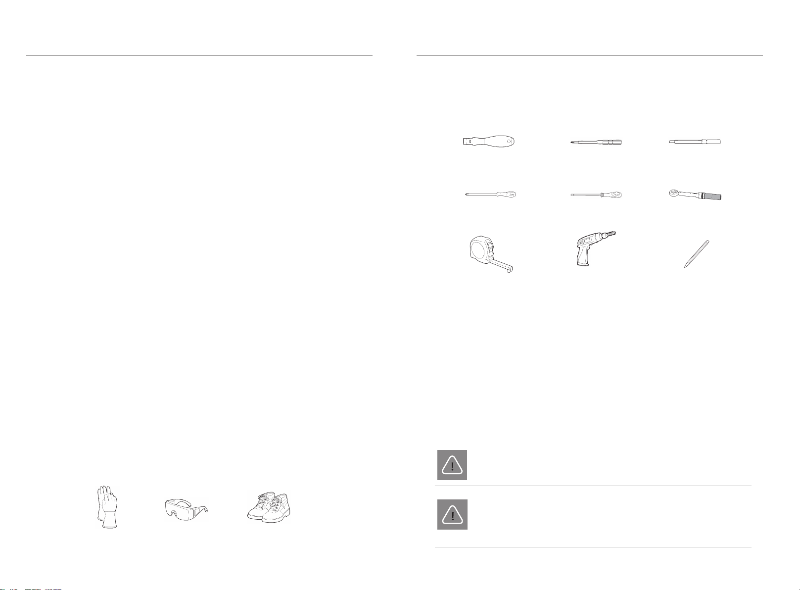
4.3 Tools
The following tools are required to install the box.
Torque Screw Driver Phillips-Screw Driver Hexagon Wrench
Phillips-Head Screw Driver Flat-Head Screw Driver Torque Wrench
Tape Measure Drill Pencil or Marker
4.4 Installation
4.4.1 Check for Transport Damage
Ensure the box is intact during and after transportation. If there are visible
damages such as cracks, contact your supplier immediately.
4.4.2 Unpacking
CAUTION!
According to regional regulations, it may require several people to
move the equipment.
WARNING!
Unpack the box package by removing the packing tape. Ensure the box
modules and relevant items are complete. See the package items on section
4.4.3 and check the packing list carefully. If there is any items missing, please
contact our company or your distributor directly.
Please follow the installation steps strictly. Our company will not be
responsible for any injuries or loss incurred by incorrect assembly
and operation.
In practice, the requirements of the parallel box installation may be different due to
enviroment and locations. In that case, please follow up the exact requirements of
the local laws and standards.
The location is far from the sea to avoid salt water and humidity, over 0.62
miles/997.79 meters
Installation
•
•
•
•
•
•
•
•
Installation
12 13
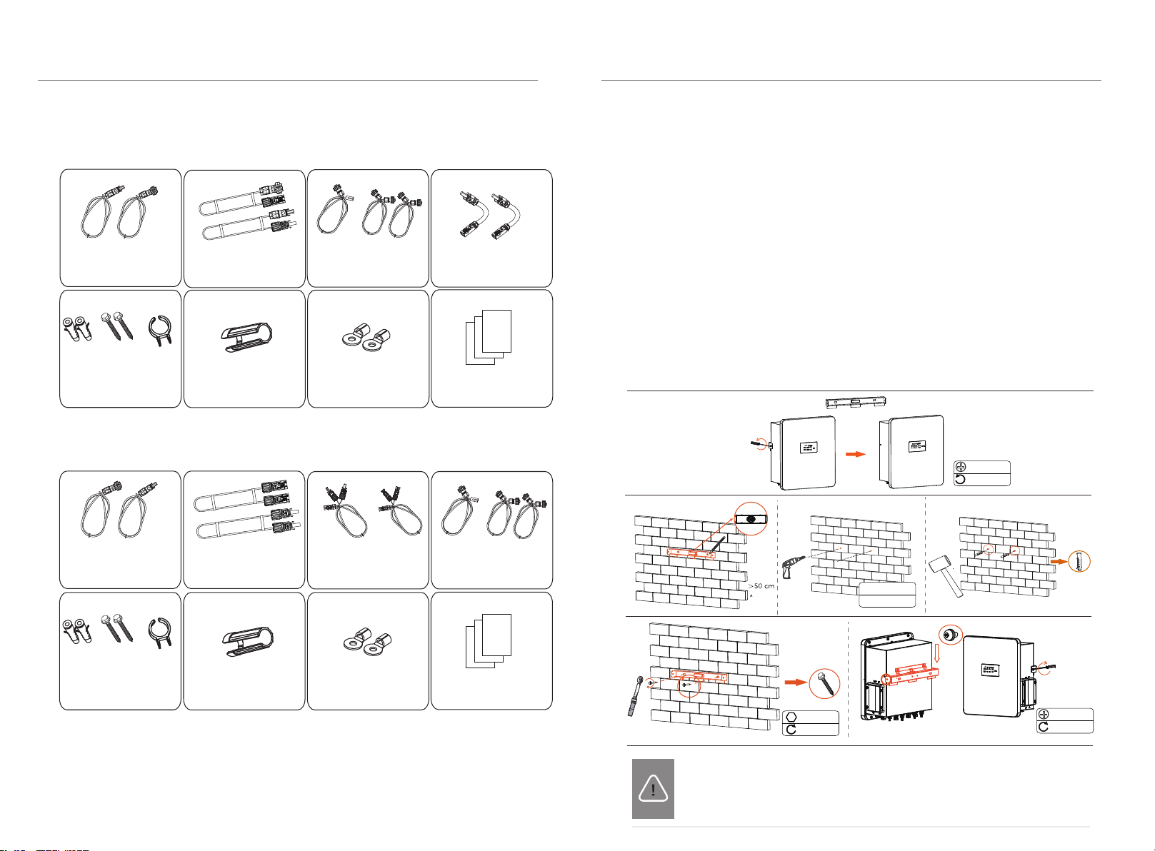
4.4.3 Accessories 4.4.4 Mounting Steps
Wall Mounting:
Step 1: Fix the wall bracket on the wall
The bracket needs to be removed from the box. Measure it and mark the
Install the expansion screw tubes on the wall, and screw the wall bracket by
a torque wrench.
Step 2: Match the box with the wall bracket
Hang the box over the wall bracket, move the box close to it and match it
on the wall bracket. Clip the buckle on the back of the box into the three
CAUTION!
Ensure that the system is always exposed to ambient air. The system
is cooled by natural convection. If the system is entirely or partially
covered or shielded, it may cause the system to stop operating.
position of the two holes. The bubble of the spirit level should be centered.
The height difference from battery modules to here should be >50cm.
Drill holes at the depth of at least 2.36 inches/60 mm by a drill.
①For use with T-BAT-SYS-HV-5.8
②For usewith T-BAT-SYS-HV-3.0
Expansion tube x2
Power Cable Disassembling
Tool x1
Power cable (+) x1
Power cable (-) x1
(6.56ft/200cm)
BMS Communication Cable
(6.56ft/200cm) x1
CAN/485 Communication Cable
(7.22ft/220cm) x2
Series-connected
plug x2
Documents
Power Cable (Heat+) x1
Power Cable (Heat-) x1
(6.56ft/200cm)
slots of the back plate accurately. (Torque: 1.0-1.2 N·m)
Expansion Screw x2
\c1382435;320204091001
Expansion tube x2
Power Cable Disassembling
Tool x1
Documents
Expansion Screw x2 Rotation Wrench x1
Power cable (+) x1
Power cable (-) x1
(6.56ft/200cm)
Power cable (+) x1
Power cable (-) x1
RS485 Communication Cable
(7.22ft/220cm) x2
BMS Communication Cable
(6.56ft/200cm) x1
M4*10
1.0-1.2 N·m
M4*10
1.0-1.2 N·m
M6*L55
5 N·m
Ø 10 drill
Depth:>60 mm
•
•
•
•
Installation
Installation
Power Connecter (+) x1
Power Connecter (-) x1
Grounding Terminal x2
Rotation Wrench x1 Grounding Terminal x2
Power cable (+) x2
Power cable (-) x2
(7.22ft/220cm)
(7.22ft/220cm)

15
14
Warning!
11.81-23.62 inches
300-600 mm
Overall Installation
CAUTION!
It is supported to only connect the slave battery modules.
It is not supported to only connect the master battery modules.
The number of modules connected at the master side and the slave side should
be consistent. At most four modules can be connected at one side.
Depending on the connection with different battery systems, there are two parallel
options, with details as follows:
① Connect with T-BAT-SYS-HV-5.8
Connect with a T-BAT H 5.8 (BMS)
and a HV11550 battery module:
Connect with a T-BAT H 5.8 (BMS)
and 3 HV11550 battery modules:
Connect with a T-BAT H 5.8 (BMS)
and 5 HV11550 battery modules:
Connect with a T-BAT H 5.8 (BMS)
4.5
and 7 HV11550 battery modules:
② Connect with T-BAT-SYS-HV-3.0
Installation
Installation
Connect with a MC0600 (BMS)
Connect with a MC0600 (BMS)
and 4 HV10230 battery modules:
Connect with a MC0600 (BMS) and 6 HV10230 battery modules:
Connect with a MC0600 (BMS) and 8 HV10230 battery modules:
Inverter
BMS+Battery
module 1
Battery
module 1
Inverter
Inverter Inverter
BMS+Battery
module 1
BMS+Battery
module 1
BMS+Battery
module 1
Battery
module 1
Battery
module 2 Battery
module 2
Battery
module 1
Battery
module 2
Battery
module 3
Battery
module 2
Battery
module 3
Battery
module 1
Battery
module 2
Battery
module 3
Battery
module 4
Battery
module 2
Battery
module 3
Battery
module 4
Battery
module
2-1
Battery
module
2-2
Battery
module
2-3
*Wiring at the back
inverter
inverter
BMS BMS
BMS
Battery
module
1-1
Battery
module
2-1
Battery
module
1-1
Battery
module
1-2
Battery
module
1-3
Battery
module
2-1
Battery
module
2-2
Battery
module
1-1
Battery
module
1-2
inverter
BMS
Battery
module
2-1
Battery
module
2-2
Battery
module
2-4
Battery
module
2-3
Battery
module
1-1
Battery
module
1-2
Battery
module
1-4
Battery
module
*Wiring at the back
1-3
*Wiring at the back *Wiring at the back

16 17
Step1.
The wire order of the communication cable is as follows:
1 2 3456 7 8
Sequence 123 4 5 6 7 8
BMS /GND /BMS_H BMS_L /A1 B1
1) Orange stripes on white
2) Orange
3) Green stripes on white
4) Blue
5) Blue stripes on white
6) Green
7) Brown stripes on white
8) Brown
It is required for the BMS to communicate with the inverter for proper operation.
The BMS communication cable is shielded by aluminum foil.
• Connecting the BMS Communication Cable
4.6 Cable Connection
Cable connection from the parallel box to the inverter:
"BAT+" to "BAT+";
"BAT-" to "BAT-";
"BMS" to "BMS".
*It is recommended to protect the cables by using corrugated pipe.
*If you plug the cable into the wrong port, you can insert the power cable disas-
-semblingtool into the gap on the side of the joint to unplug the cable easily.
* Please refer to "battery connection" section of the inverter's user manual/quick
installation guide for details about inverter connection.
Remember to always keep the unused port plugged.
NOTE!
NOTE!
Step 1. Prepare a 6 mm² BAT cable. Use a wire stripper to strip the 7mm insulation
layer of the wire end.
Step 2. Tighten the cable with the insulation layer stripped and insert it into the
battery pin contacts, make sure all wires are well connected.
Step 3.Tighten the BAT pin needle and the wiring harness to make the connection
tight without looseness.
Step 4.The battery connectors are divided into 2 parts - the plug and the fastening
head. Insert the cable through the fastening head and the opposite plug.Note that
the red and black lines correspond to different of plugs.
Step 5. Force the cable pair into the plug, will a "click" sound ,which indicates that
the connection is complete.
Step2.Step3.
Step4.Step5.Step6.
7mm
6 mm²
Wire stripper
+
-
+
-
+
+
+
-
-
-
Click!
Click!
Step7.
Step 6. Tighten the fastening head and into insert the corresponding positive
and negative (BAT-/BAT+) ports of the inverter.
Step 7: Insert the cable into the corresponding BAT port (+), (-) of the inverter.
4.6.1 Connecting Cables to Inverter
NOTE!
Installation Installation
* If the connector of the T-BAT-SYS-HV-3.0 controller does not match the
connector provided with the accessory cable, you can trim the blue connector
and replace it with a black connector. The replacement should follow the rule
of male-to-male and female-to-female connections. The Installation mode of
black connector is as follows:
DC socket housing(+)
screw connection
DC plug housing(-)
screw connection
spring
chamber
wire strands
②① ②
④
③
BMS
BAT- BAT+
To Inverter BMS
BAT- BAT+
The recommended installation distance between the box and the battery group
(including slave group and master group) is 11.81-23.62 inches /300-600 mm,
and the distance between the modules is 9.84 inches/250.00 mm.
NOTE!
Before installation, please make sure that the wall can bear the weight of the
batteries installed. If not, please take the mode of floor installation.
slave
inverter
main

Installation
18 19
4.6.2 Connecting Battery Modules
①For BMS Parallel box-Ⅱ G2 + T-BAT H 5.8 + 1/3/5/7 HV11550 battery pack(s)
From BMS Parallel box-Ⅱ G2 to T-BAT-SYS-HV-5.8:
Main "BAT+" to T-BAT H 5.8 "BAT+";
Main "BAT-" to T-BAT H 5.8 "BAT-".
If there is(are) a port(s) that is(are) not wired after wiring is completed, please
don't forget to put the waterproof cap(s) on the port(s).
To form a complete circuit, connect "-" and "YPLUG" with series-connected
cable on the right side of the last battery module. Please check
T-BAT-SYS-HV-5.8 User Manual/Quick installation guide for detailed tutorial
on cable-connecting between T-BAT H 5.8 and HV10230 battery modules.
NOTE!
②For BMS Parallel box-Ⅱ G2 + MC0600 + 2/4/6/8 HV10230 battery modules
From BMS Parallel box-Ⅱ G2 to T-BAT-SYS-HV-3.0:
Main "BAT+" to MC0600 "BAT+";
Main "BAT-" to MC0600 "BAT-".
Regardless of how many battery modules installed, please put a waterproof cap
on the communication port of the unconnected port of battery module.
Slave "BAT+", Slave "Heat+" to HV10230 "B+";
Slave "BAT-", Slave "Heat-" to HV10230 "B-".
Please check T-BAT-SYS-HV-3.0 User Manual/Quick installation guide for detailed
tutorial on cable-connecting between MC0600 and HV10230 battery modules.
NOTE!
Slave "BAT+" to HV11550 "+";
Slave "BAT-" to HV11550 "XPLUG".
Installation
Ⅱ
B
+
B
-
20 21
Commissioning
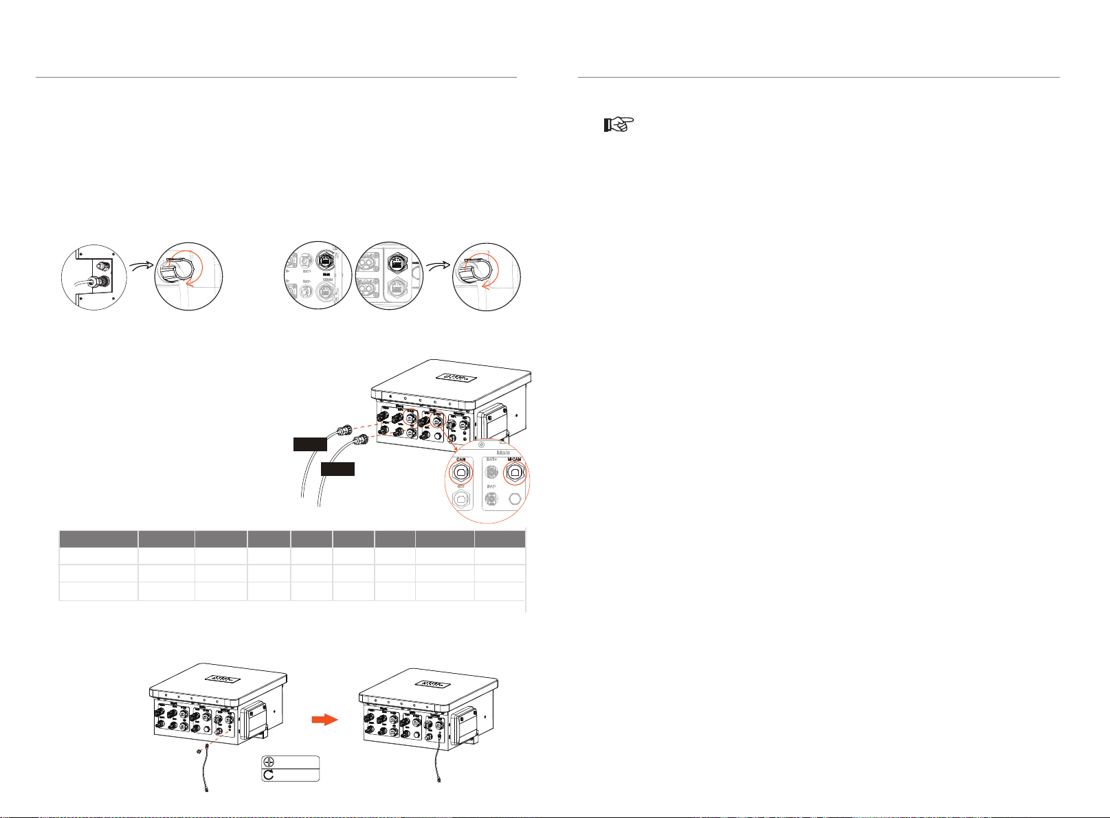
4.6.3 Connecting Communication Cables
Sequence 1 2 3 4 5 67 8
SLAVE RS485 I
VCC_485
GND_485
B2 N- P+ A2
VCC_485_2
GND_485
The wire order of the communication cable is as follows:
1) There is a protection cover for the RS485 connector. Unscrew the cover and plug
one end of the RS485 I communication cable to the RS485 I connector. Tighten the
plastic screw nut which is set on the cable with a rotation wrench. The operation is
the same as above if connecting to the COM1/BMS connecter.
4.6.4 Connecting the Ground Wire
Remove the M5*10 screw from the bottom of the BMS Parallel box-Ⅱ G2 with a
screwdriver, and then screw the groung wire(10 AWG/6 mm) to the corresponding
grounding port.
5 Commissioning
5.1 Configuring the Box
2) Connect the communication cable from the parallel box to the COMM/BMS/RS485 I
communication port that is on the left side of the battery module.
For T-BAT-SYS-HV-5.8 (RS485 I, BMS): For T-BAT-SYS-HV-3.0 (COM1, BMS):
HV11550 to Parallel box SLAVE "RS485 I";
HV10230 to Parallel box SLAVE "S-CAN";
T-BAT H 5.8 or MC0600 to Parallel box MAIN "M-CAN".
MAIN CAN
SLAVE CAN VCC_1 GND VCC_2 CANH CANL GND N- P+
///A1 B1
GND BMS_H BMS_L
• The DIP switch is used to configure the communication between battery
module(s) and the device. By default, only two groups of batteries can be
matched for use.
• The black-start function is only used in an off-grid application and when
there is no other power supply. To Black-start, hold down the button for 20
seconds until the soc light starts flashing blue to indicate successful black-start.
If the box is started in the black-start mode, remind that even when there is no
BMS communication, the port still contains high voltage with risk of electric
shock.
If the BMS communication has still not been established within 3 minutes after
starting the black-start mode, it indicates that the black start fails to start.
• After the BMS Parallel box- G2 is powered on, if the indicator lights Ⅱ
alternate flashing red and green for more than two minutes, and then change
to green flashing with the inverter reporting “Batt_ClusterCommuCountMis-
-Match", please check the communication connection of the second group of
BMS Parallel box- G2, as well as the power-on status of T-BAT H 5.8 or Ⅱ
MC0600 connected to the second group.
• After the BMS Parallel box- G2 is powered on, if the indicator lights Ⅱ
alternate flashing red and green for more than three minutes, and then change
to flashing red for one second and off for three seconds, with the inverter
reporting "BMS_Internal_Err 1", it indicates that the corresponding slave at
position 1 failed to connect to the communication successfully. According to
the error number, please check if the communication line of the slave at the
corresponding position is properly connected.
M5*10
2.5-3 N·m
B
+
B
-
Installation
When BMS Parallel box-Ⅱ G2 is connected to T-BAT-SYS-HV-5.8 battery
modules, if master group's CAN is connected to slave group's CAN port, it can
operate and function normally. However, the master group cannot be
upgraded properly in this configuration.
NOTE!
Slave
Main
2223
Commissioning
5.2 Commissioning
Verify the model number of each battery module to ensure that they are all the
same model.
Frequently pressing the POWER button may cause a system error. Allow at least 10
seconds after pressing the POWER button prior to making another attempt.
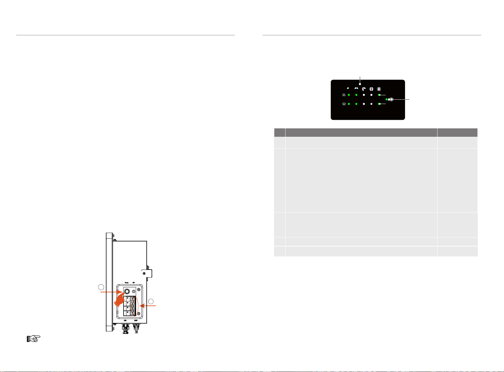
5.3 Status Indicators
The LED indicators on the front panel of the BMS and the battery modules indicate
the operating status.
The capacity indicators show the state of charge (SOC):
When the battery module is neither charging nor discharging, the indicator
lights are off.
When the battery module is charging, a part of the blue LED flashes once
every 5 seconds, and a part of the blue LED is on. Take SOC 60% for instance,
when in charging state:
1) The last two blue LED indicators are on
2) The third blue LED indicators flash once evey 5 seconds
When the battery module is discharging, the blue LED indicators flash once
every 5 seconds. Take SOC 60% for instance, when in discharging state:
1) The last three blue LED indicators flash once every 5 seconds
Description of the status indicators of BMS is shown as follows:
4
5
Protection
Normal
Upgrade for BMS
Power off
No.
1
2
Mode
Inverter sends
Status of BMS
Green LED flashes on 1 sec and off for 4 sec
3
After all battery modules are installed, please follow the following steps to
start the box:
1) Open the waterproof cover board of the box;
2) Move the circuit breaker switch to “ON”;
3) Press the POWER button to start the box;
4) Reinstall the cover board to the box;
5) Turn on the inverter DC switch;
6) After starting the box, please confirm that the waterproof cover board is
closed again.
Status Light
Capacity
25% 50% 75% 100%
SOC
Status Light 2
Status Light 1
NOTE!
Idle command
The status light of one of the two groups is off if it works normally.
The general status light will flash green (light for 1 second and off
for 4 seconds) will stay on green light if an inverter is connected.
Green LED flashes once every 0.5 sec
Light off
(1) When both groups have faults, the status lights of the two
groups will flash red at intervals of 0.5 seconds. The general
status light will keep the red light on.
(2)When one of the two groups has a fault, and the status light
of one group flashes red (light for 1 second and off for 4
seconds), while the other group keeps the green light on.
* When the fault is reported, the fault light of the
corresponding branch will stay red.
•
•
•
Commissioning
• The BMS Parallel box-II G2 must be connected to two groups of batteries
simultaneously in order to function properly, and the number of slaves in both
groups must be the same. The second group of BMS Parallel box-II G2 must
contains a T-BAT H 5.8 or Mc0600. And the two battery circuits connected to the
BMS Parallel box- G2 must be all HV11550 or all HV10230, and it is not allowed to Ⅱ
connect one group with HV11550 batteries and the other group with HV10230
batteries.
• It is prohibited to plug or unplug the power line during the operation of the BMS
Parallel box- G2. Ⅱ
3
2

2425
6 Troubleshooting
Check the indicators on the front to determine the state of the box.
A warning state is triggered when a condition, such as voltage ortemperature, is
beyond design limitations. Boxperiodically reports its operating state to the inverter.
When the box falls outside the prescribed limits, it entersinto a warning state.
Use the monitoring software on the inverter to identify what caused the warning.
The possible warning messages are as follows:
Troubleshooting
When a warning is reported, the inverter immediately stops its operation.
1) Ensure the power cable is
correctly and properly connected
to the power connector (XPLUG)
of the BMS
2) If the first step still does not
work, contact your distributor or
our company directly.
Troubleshooting
BMS_TemHigh Battery over
temperature
BMS_TemLow Battery under
temperature
BMS_CellImblance The capacities of
cells are different
BMS_Hardware_Protect Battery hardware
under protection
BMS_Insulation_Fault Battery insulation
fault
BMS_VoltSensor_Fault Battery voltage
sensor fault
BMS_TempSensor_Fault
Battery
temperature
sensor fault
BMS_CurrSensor_Fault Battery current
sensor fault
BMS_Relay_Fault Battery relay fault
BMS_Type_Unmatch The type of BMS
isunmatched
BMS_Ver_Unmatch The version of
BMS isunmatched
Warning Messages Description Troubleshooting
Wait until the temperature of the
cells returns to the normal state.
Wait until the temperature of the
cells returns to the normal state.
Warning Messages Description Troubleshooting
1. Move the DIP switch to the
correct position;
2. Check if the communication
cable between battery
modules is correctly and well
connected.
BMS_Internal_Err
1) DIP switch on the
wrong position
2) The communication
between battery
modules is interrupted.
1) Move the DIP switch to the
correct position
2) Check if the communication
cable between thebattery
modules is correctly and
properly connected.
BMS_OverVoltage Battery over voltage
BMS_LowerVoltage Battery under voltage
BMS_ChargeOCP Battery charge over
current protection
BMS_DishargeOCP Battery discharge over
current protection
Contact your distributor or our
company directly for servicing.
Contact your distributor or our
company directly for servicing.
Contact your distributor or our
company directly for servicing.
Contact your distributor or our
company directly for servicing.
Contact your distributor or our
company directly for servicing.
Contact your distributor or our
company directly for servicing.
Contact your distributor or our
company directly for servicing.
Contact your distributor or our
company directly for servicing.
Contact your distributor or our
company directly for servicing.
Contact your distributor or our
company directly for servicing.
Contact your distributor or our
company directly for servicing.
Contact your distributor or our
company directly for servicing.

2627
7 Decommissioning
7.1 Dismantling the Box
Disconnect the cables between the box and inverter.
Disconnect the series wiring terminal on the box.
Disconnect the rest of cables.
7.2 Packing
Pack the box in the original packaging.
If the original packaging is no longer available, use an equivalent carton or box that
meets the following requirements:
Suitable for loads over 154.32 lbs/69.94 kg
Properly closed and sealed
Decommissioning Maintenance
8 Maintenance
If the ambient temperature for storage is 86°F~122°F/30℃~50℃, recharge
the batteries at least one time every 6 months.
If the ambient temperature for storage is -4°F~-86°F /-20℃~30℃, recharge
the batteries at least one time every 12 months.
Maintain periodically
Only qualified person may perform the following works.
During the process of using the box,the manage person shall examine and
maintain the machine regularly.The concrete operations are as follows.
1) Check that if the cooling fans on the rear of house are covered by dirts,
and the machine should be cleaned and absorbed dust when necessary.
This work shall be check time to time.
2) Check that if the indicators of the box are in normal state,check if the keys
of the box are in normal state,check if the display of the system is normal.
This check should be performed at least every 6 months.
3) Check that if the input and output wires are damaged or aged. This check
should be performed at least every 6 months.
4) Check whether the ground terminal and ground cable are securely con-
-nected and all terminals and ports are properly sealed every 12 months.
5) You should get the box panels cleaned and their security checked at least
every 6 months.
To shut down the system and dismantling the box, please follow the steps below:
According to the actual situation, please turn off the breaker located between
the inverter and the parallel box.
Press the POWER button to shut down the box.
Move the circuit breaker switch to the OFF position.
Ensure that every indicator on the box is off.
If the batteries have not been used for more than 9 months, these batteries
must be charged to at least SOC 50 % each time.
For the first installation, the interval among manufacture dates of battery
modules shall not exceed 3 months.
If a battery is replaced or added for capacity expansion, each battery's SOC
should be consistent. The max. SOC difference should be between ±5%.
If users want to increase their battery system capacity, please ensure that
the SOC of the existing system capacity is about 40%. The manufacture
date of the new battery shall not exceed 6 months; in case of exceeding 6
months, please charge the new battery to around 40%.
•
•
•
•
•
•
•
•
•
•
•
•
•
•
•
•
•
•
If needed, unmount the box from the wall bracket to remove it from the wall.

9 Warranty
Triple Power protects this product under warranty when it is installed and used as
listed in this manual.
in this manual will immediately void all warranties on the product.
Triple Power does not provide warranty coverage or assume any liability for direct
or indirect damages or defects that result from the following causes:
Force majeure (flooding, lightning strike, overvoltage, fire, thunderstorm, etc.)
Improper or noncompliant use
Improper installation, commissioning, start up or operation (contrary to the
guidance detailed in the installation manual supplied with each product)
Inadequate ventilation and circulation resulting in minimized cooling and
natural air flow
Installation in a corrosive environment
Damage during transportation
Unauthorized repair attempts
Failure to adequately maintain the equipment. An on-site inspection by a
qualified technician is possible following 120 months of continuous use.
Warranty claims made beyond 120 months from date of commissioning may
be declined if it cannot be demonstrated that the equipment has been
adequately maintained.
External influence including unusual physical or electrical stress (power failure
surges, inrush current, etc.)
Use of an incompatible inverter or devices
28
Warranty Warranty
Registration
Form
For Customer (Compulsory)
For Installer
Name
Product Serial Number
Date of Commissioning
Installation Company Name
Installer Name Electrician License No.
Phone Number
Address
State
Country
Zip Code
Email
Module Brand
Module Size(W)
Number of String Number of Panel Per String
Battery Type
Brand
Number of Battery Attached
Battery ( If Any )
Module ( If Any )
Date of Delivery Signature
Please visit our warranty website: https://www.solaxcloud.com/#/warranty
to complete the online warranty registration or use your mobile phone to
scan the QR code to register.
For more detailed warranty terms, please visit SolaX official website: www.solaxpower.com
to check it.
Violation of the installation procedure or use of the product in any way not described
Connect to other brands of inverter without authority from our company.
•
•
•
•
•
•
•
•
•
•
•
•

PLEASE REGISTER THE WARRANTY
IMMEDIATELY AFTER INSTALLATION!
GET YOUR WARRANTY CERTIFICATE
FROM SOLAX!
KEEP YOUR INVERTER ONLINE & WIN
SOLAX POINTS!
Open your
camera app
and point
your device
at the QR
code
Wait for the
camera to
recognize
the QR code
Click banner
or notification
when it appears
on the screen
Warranty
registration
page will be
loaded
automatically
1
2
3 4
Not ificat ion
Cli ck the no tifica tion ba nner
OK
Table of contents
Other SolaX Power Batteries Pack manuals


