Nilar EC Series User manual

THIS INSTRUCTION MANUAL IS AN ORIGINAL
Document ID: 73-H001
Battery Pack, EC
INSTRUCTION MANUAL

#$%&$'(&)
!"
$*+ ", " ++ + "-
+" !+
. ++++
$ /"+""""0+!"
" +/ !""!+
10 + /" +"+ -
+
$"" /" +"0)02!3)24567879&-
9/39(4!56779&" +:" /
"%#!57;879&
$" / +09&"!5;7;;79<3=!>4$/* "
! "-"
$"" 1 9"99?319994!557@79&$
+7 /+"" "-*+""
+!""++
" 0%394@75;% -9!-
:" + 3%941* 0%9?
+ " "!
!"
"+73-H001
2 #
5 ,! 5A;6
5 %! 5AA
!" 5A@6
% "! 5A@8

#$%&$'(&)
!"
$ 0! " ++ " +"+
"%"+"!" * " * $ "!""+0
,
1. Safety Information < ++
2. Warranty %+ (-
3. Environment - (- /
4. Function description <" +" -
. Transportation, lifting and
storage
-" "
6. Installation +
7. Operation '" -
8. Maintenance "! - " (
9. Decommissioning -+
10. Troubleshooting #+ ' - "

#$%&$'(&)
!"
Table of contents
#++
#+*
5
<0 "
5
15
9!
6
B" 6
6
* +"/"6
65
"(&3(&4;
6
(&
66
# (&5
8
$ -+"
8
$
85
(!"+6
8
#6
;
8
;
<" ;
;5
,+ ;
;
'+/*;
;6
+/*
;8
# 3#45
'5;
5;
5
5;
% 5;
6
#+" 5;
8
+5

#$%&$'(&)
!"
A
(5A
A
,! "5A
A5
"5A
@
5@
@
$" 5@
@5
," 5@
$/
"
"C"
"C5+/-$"5

#$%&$'(&)
!"
Figures
B'!!0+662-52"@;2/* (&3++46
B5"+662/*6
B( +662/*0"C(&6
B6, +662*C(&8
B8662*0(&+;
B; - !3D4 -,CA8A
B -!34 -,CA8
BA - !3D4/-,C6;6
B@ -!34/-,C6;A
B'!!0+(&0!"!"
B"" +(&A
B5- A
B -,C@A61+7 "! /3 0 4@
B6 - -)9(#78@
B8/ - @
B; / -(C8@
B, 0+"" @
BA"5-
B@ --#""%E68
B5 -5F%E68-,'$G)%E68(G$9%(5
B5B-
B55 B-(C86
B5,0-
B56 ,0-,C@6AA1+7 "! /3 0 4
B58*+ 6
B5; +/*-;
B5 +/*-5
B5A, +,
B5@+"+!"!A
B + /(&A
B +(&A
B5 +B@
B +5620 4@
B6 +/ @

#$%&$'(&)
!"
B8!0+/!"+(&5
B; +!34/-3(& " "45
B +!34/-+3(& " "45
BA + !3D4/-3(& " "45
B@ + !3D4/-+3(& " "45
B6 ""/-++55
B6 0(&!" !"55
B65 + //*=>55
B6 +/5
B66B " +/ 0""5H *+
/*=>5
B68 ++/ 5
B6;B " +5620 45
B6 +!34/3(& " "456
B6AB " +!34/3(& " "456
B6@+ */56
B8B " +*//0/*=>"=>58
B8B " +*/ +/ 3(& " "458
B85 + !3D4/58
B8B " + !3D4/58
B861999 /5@
Tables
$/$ ++/*! : ID5
8
$/5 +! A
$/%/0"""C 8J#'6

#$%&$'(&)
!" Page 1 (32)
1. Safety Information
$ ! ++ /
+/*
$!" K-"+ !
?+"" %+ +
+ --
"" B""
+" +-"?
(#+#3(##4
1.1 Safety markings in this instruction
1.2 General warnings and cautions
1%<L
% *+ *"+"
"
1%<L
$/* /"++
,
•1*0/*
•%" "
/ 1+"
0 +
1%<L
% *+:" +" C "
1%<L
+/+ /C "
/ '
5
"709 +
C !/
1%<L
0 "+ +
" ""-! "
/?+" !
1%<L
/*!"
&$'L
+/*3 4 ""-
+0
• ++
/
•9
•$ *+//"
*- "
$+-+0 "
•/*
•"+"
/*
•'/*00"
• /*
• /*+
"+" +
&$'L
$!":" - "
+"
&$'L
"0!
!"+! !"""
C "
&$'L
$" /C "?"
3" 4"/K +"0?"
/" "
&$'L
%! -
/ -* -"0 0
""
!/
&$'L
." + ""
$C*0
? ""
+
+/+
L
1%<
L
$C*0
""
+ +
/ "0/"
K"7"
"L
&$'
L

#$%&$'(&)
!" Page 2 (32)
2. Warranty
%"""0" 0+
=1+>+0
+ " "
B+0" 0+
=$ "" >

#$%&$'(&)
!" Page 3 (32)
3. nvironment
$ 0+/0/
* "
$ *+/"
!00*+
" "" ++3 +
!"4,
"+" !
1/* " "++-
* + /+
/!/*
!+
+$ "
+ ""
3.1 Compliance
" 0+0
!"! "
•9&"!5;7;;793=!>4
$/* "!
"-"
•1 9"99?
319994!557@79&
•% +:" /
"%#!57;879&
•" 0%
394@75;% -
9!-:"% +
3%94

#$%&$'(&)
!" Page 4 (32)
4. Function description
$ 0" /++!
+/*
Figure 1: Overview of 144V, 120V and 96V battery packs incl. IMU (from left to
right)
Figure 2: Build-up of a 144V battery pack
4.1 Battery pack specification and build-up
/*/0"5"
352"4- /*
/0A"5" 9"0
/
-0/* ""
" "+?-0+
"//*"
0"-"" 0
/""/ "
* " "/ "
0C/!A
2$C/! /""
-0/* +"
Figure 3: Measurement illustration of 144V battery pack with length incl. and
excl. IMU

#$%&$'(&)
!" Page 5 (32)
Table 1: Technical specification of battery pack in various sizes @ +20oC
Properties 96V 108V 120V 144V Unit
Rated energy 0.96 1.08 1.2 1.44 kWh
Nominal voltage 96 108 120 144 VDC
Max. ontinuous
harging power 2.88 3,24 3,6 4,32 kW
Max. ontinuous
dis harging power 2.88 3,24 3,6 4,32 kW
Dimensions (LxHxW)
248 x
306 x
127
273 x
306 x
127
293 x
306 x
127
337 x
306 x
127
mm
Dimensions ex l.
IMU
1
(LxHxW)
210 x
306 x
127
235 x
306 x
127
255 x
306 x
127
299 x
306 x
127
mm
Weight 24 26 29 34 kg
Prote tion lass
(Battery pa k ex l.
IMU and terminals)
IP54 IP54 IP54 IP54 IP
Prote tion lass
(Battery pa k) IP20 IP20 IP20 IP20 IP
Max. battery pa k
pressure (rel.) 5,5 5,5 5,5 5,5 bar
Battery pa k voltage
range 80-132 90–149 100-165 120-198 V
Max. allowed
battery pa k
temperature
+58 +58 +58 +58
o
C
Max. allowed
battery pa k relative
humidity (without
ondensation)
90 90 90 90 %
Ambient
temperature range
-20 to
+50
-20 to
+50
-20 to
+50
-20 to
+50
o
C
Pollution degree 2 2 2 2 Class
Overvoltage
ategory III III III III Category
1 IMU = Integrated Monitoring Unit (see section 4.2)
M
N
O
P
Q
Figure 4: Parts of 144V Battery pack excl. IMU
4.1.1 Rupture disc (① not displayed)
$/* +"0"
!" +;/$"
" "+/*$
" !""/ !"
4.1.2 Module voltage terminals (②)
9"!" (&0!
"! /
+/*"+
" "/*
4.1.3 nd pieces (③, blue ●)
$ " "+/*
" ?" +
/*

#$%&$'(&)
!" Page 6 (32)
4.1.4 Steel strapping bands (④, steel grey ●)
$/* /"/34
/" $+ /"
" 0
+/*
4.1.5 Module (⑤, light and medium grey ●● )
$52" /"/*+/
* " "
" 0"+"
! +52
4.2 Integrated Monitoring Unit (IMU)
$(& "++/*-
(&/*$ /
* "C/*
+ !+
, !3D4
!34
!"+ +(&
"(&3(&4
Figure : 144V Battery pack with IMU on front
"/(&
•("! (up to 12 inputs per battery
pack)
•*!
•* (1 sensor per battery
pack)
•* (1 sensor per battery pack)
•# 7(1 sensor per battery
string, i.e. several series connected battery packs)
For a more detailed description of the IMU, please refer to the EDS
description (doc. Id: SPN-170063-88-H001)
#$%&$'(&)
!" Page 7 (32)
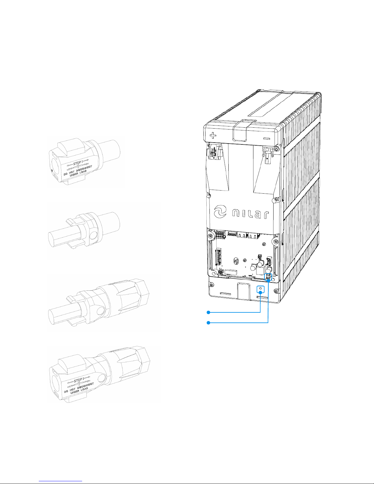
4.2.1 Negative (-) and positive (+) terminals
$ " "+
(&$ +=,C#C
,2- >$/
/* "!
=,C#C,2-/>""
/""++
0"! ""$ "
""?0/*
Figure 6: Design, positive (+) chassis connector, type Phoenix 180 180
Figure 7: Design, negative (-) chassis connector, type Phoenix 180 177
Figure 8: Design, positive (+) cable connector, type Phoenix 1774674
Figure 9: Design, negative (-) cable connector, type Phoenix 1774687
4.3 Connections IMU
+(&/+""
!"
M
N
Figure 10: Overview of IMU with cover lid removed
4.3.1 Operation L D (①)
$)9" +(&
" "+0/

#$%&$'(&)
!" Page 8 (32)
Table 2: Description of visual signals
2 #
● Green Normal mode (system measuring is
active)
● Red Active alarm
● Blue Power save mode (voltage measuring
disabled)
● Yellow
Start-up sequence (IMU requests
settings input from superior control
system)
(& "0+
<off<off
(& ""
?0+
<R0<R0
(&0 !"00+
<<
(&0!0
"+
%"off %"off
(& ?0!
0+
%"R0%"R0
(&0 !"00+
<<
4.3.2 Reset button (②)
% /(&0/
"
4.3.3 Overview - connections
$+0 7 0 !/
(&"+ C"+0
O
P
Q
S
T
U
Figure 11: Indicated connection points of IMU
4.3.4 Current (③, blue
●
)
$ + 0
7"
,$-876,2-83,C
@A6A@A64
Figure 12: Current connection, schematic

#$%&$'(&)
!" Page 9 (32)
Figure 13: Design Current connector, type Phoenix 1984031. With front-/outside
visible (screws on top)
$(& " "+ 0++
+)9(-#766#78
Figure 14: Design, Current sensor, type LEM DHAB S/1 1
4.3.5 Ambient temperature sensor (④, purple
●
)
$*" =G6> "+
C/
(C83 "4
Figure 1 : Ambient temperature sensor connection, schematic
Figure 16: Design Ambient temperature sensor connector, type Molex 1103
4.3.6 Address setting (⑤, brown
●
)
1 !/*
!/*7(&?
?"+3"" 4$ "+
/, 0
Figure 17: DIP-switch for address setting

#$%&$'(&)
!" Page 10 (32)
4.3.7 CAN1 and CAN2 (⑥, green
●
)
$ 3%E687A,A4 "
"/*"
/ +0
(& " /" 4.4Signals IMU.
/ 0 !
+5F"$!"
" " "
/* " "
+/ +%E68
$(&0/ +!+65A23"
2,V6,VA4 "V8
$-/* "%E68-5F3,'$
G)%E68(G$9%(54
#""%E68
Figure 18: CAN1 and CAN2 connection, schematic
Figure 19: Design, CANopen connector, Shielded RJ4
Figure 20: Design, CANopen termination 120Ω RJ4 , type CPOINT XLRJ4 -
DMXTERM-120
4.3.8 Fan (⑦, yellow
●
)
$ 0C++
/*
(C863 "4
!525623""
4
(C+051
Figure 21: Fan connection, schematic

#$%&$'(&)
!" Page 11 (32)
Figure 22: Design Fan connector, type Molex 1103-0400
4.3.9 Power In (⑧, red
●
)
$5620 (&
"*"=,0>
,$-876,28-3,C
@6AAA884
!5623525A20"4
,0 -81D+0C53++
"4
Figure 23: Power In connection, schematic
Figure 24: Design Power in connector, type Phoenix 1934887. With front-
/outside visible (screws on top)
For a more detailed description of the IMU, please refer to the EDS
description (doc. Id: SPN-170063-88-H001)

#$%&$'(&)
!" Page 12 (32)
4.4 Signals IMU
$+0 "/(&
4.4.1 Module voltages
$! !+
"+! +"+"-
0/"
"""! -/"
!+/* ""
" /*!!
4.4.2 Current sensor
$ ! +/
+0""!+ +
"+"-0/"
4.4.3 Pressure sensor
/
! /*
/*" -
/*! +
+"+"-0
/"""C/
$C/
/"" /
*+
4.4.4 Battery temperature
$ /*
+ +
"+"-0/""
"C/
!/+!
$" ""0+
"3 /"
C/ 4
4.4.5 Fan
$ ++/"K "
J " $
"+"C/
For a more detailed description of the IMU, please refer to the EDS
description (doc. Id: SPN-170063-88-H001)

#$%&$'(&)
!" Page 13 (32)
5. Transportation, lifting and storage
$ " 0"
" ?0/ "-!"-+"-
" "
5.1 Transportation
1 /*
" " /
*-00/" /" +
5.1.1 Packaging and outside conditions
/* "!"0"
*! "
$+0 *+! /"
" +*3
" 4
+ " " !"
•"
•%" /
• !
+""-0"! **
++"+ +
/ ""*"
"!""!"
$ " /0
WX"D;X"!"@J
30" 4
Note! The relation between temperature and the recommended
maximum storage time as described in section .3 is also applicable for
longer transportation durations.
5.1.2 Transportation of Battery packs
/* "?&!"
*"*0 "/ -"-
"
" " " ?"0
/* /"
" " " ?"+/
* "/ ? +!
* /*
"+" " " - @&/"
,#3,#4&6@;" -
*(""- !
1/ ?"+/*
"//* +"
" " "/Batteries,
dry +" " $3&
/4+1/ "-0" =
% ">"#,! /354
/""" + /
1/-"$<%
$/* / "+
! "/ *"
!!"" -
*
, / ! +
"+!""/* !
+":" !"
,
!+"!" +
"""+!/*
, * /
* "
0" "
3 ;'4
&$'
L
Table of contents
Other Nilar Batteries Pack manuals


