Nilar Home Box 288VDC User manual
QUICKINSTALLATIONGUIDE
210016E&210016EP
Validforproducts:

Importantinformaon
Readcarefully
Keepthisinformaonforfurtherreference
WARNING
Thisproductcontainspowerfulbaerypacks(NiMH) andis
suppliedbymulplehazardouselectricalsources.Bewareof
storedandresidualenergies.
Obeylocalregulaonsforliveworkingwhencasing/doorisopen.
Wearelectricallyinsulatedgloveswhenhandlingbaerypacks.
Baerysurfacesmaycarryhazardousvoltageduetolowered
insulaonresistance.Donotplacebaerypacksonconducve
surfaces.
Riskforelectricshockandarcingifproductisusedincorrectly.
Thebaerypackscannotbeturnedoffelectrically.Pleasenote:
Workonlywithonebaerypackterminalattheme.
Rupturediscmayreleaseelectrolyteduringabnormaluse.
Wethereforerecommendwearingsafetyglasses.
Riskforelectricalhazardsifproductisexposedtorainor
moisture.
Donotoperatetheproductwithsuspectedfailures.Ifyou
suspectthattheproductisdamaged,haveitinspectedby
qualifiedservicepersonnel.
Neverinstalladamagedbaerypackoradamagedinsulaon
tray.
Donotblockorcovertherupturediscoutletonthebaerypack.
Ifafireoccurs,itcanbeexnguishedbyusingCO2.Ensurethat
fireexnguishersareavailable.
CAUTION
Ifabaerypackisdamagedmechanically,thefollowingmay
occur:
Highheatgeneraononthesurfaceofthebaerycells.
Electrolytemayescape.
Eventualsmokefromthebaerypackscanirritatethe
skin,eyesandrespiratorysystem.
Therefore,followtheseguidelines:
Donotopenthebaerypacks.
Donotmodifyormechanicallydamagethebaerypacks.
OperatetheNilarHomeBoxonlywithintheallowed
operangrange.
Donotshort‐circuitthebaerypacks.
Donotconnuetousethebaerypacksaeridenfied
asfaulty.
Itisrequiredthatasmokealarm,preferablywithconnected
surveillancefuncon,isinstalledincloseandstrategical
conneconwiththeinstallaonoftheproduct.Furthermore,the
installaonofagasalarmthatwarnsincaseofhighlevelsof
hydrogenisrecommended.
Alwaysinstalltheproductinawell‐venlatedlocaon.
Toavoidpotenalhazards,usethisproductonlyasspecified.
Donotoperatetheproductwithcoversremoved.Ifcoversare
removedduringe.g.repair,donottouchanyexposed
connecons.
Theproductshallnotbeexposedtoliquids(notevendrippingor
splashing)andobjectsfilledwithliquidsmustnotbeplacedon
orclosetotheproduct.
Removepersonalmetalitemssuchasrings,bracelets,necklaces,
andwatcheswhenphysicallyhandlingtheproductsinceitcan
resultinashort‐circuitcurrentcausingsevereburn.
Keepproductsurfacescleananddry.
THISQUICKGUIDEISONLYINTENDEDTOBEUSEDBYINSTALLATIONPERSONNELWITHPREVIOUSINSTALLATION
EXPERIENCEANDFULLUNDERSTANDINGOFTHEPROCEDUREANDSAFETYWARNINGSEXPLAINEDANDDESCRIBEDINTHE
MOREEXTENSIVEINSTRUCTION MANUAL (73‐H014)!
IFUNCERTAINTYARISES,ALWAYSREFERTOINSTRUCTION MANUAL (73‐H014)!
THEINSTRUCTIONMANUALCANBEDOWNLOADEDAT:hps://www.nilar.com/partner‐login/

PERSONALPROTECTIVE
EQUIPMENT(PPE)
AlwaysusePPEduringhandlingandinstallaonofproduct.At
minimumthisincludessafetyshoeswithsteeltoe,safety
glasses,andelectricallyinsulatedgloves:
TOOLS&
ACCESSORIES
TX20 Torxscrewdriver,size20
HX4 Hexscrewdriver,size4
PH2 Crossscrewdriver,size2
WS Wirestripper
WARNING&CAUTION
SYMBOLS
Thefollowingwarningandcauonsymbolsareusedthroughout
thedocument:
GENERAL
CAUTION
WARNING
CRUSHHAZARD
WARNING
HAZARDOUS
VOLTAGE
CAUTION
HEAVY
WEIGHT
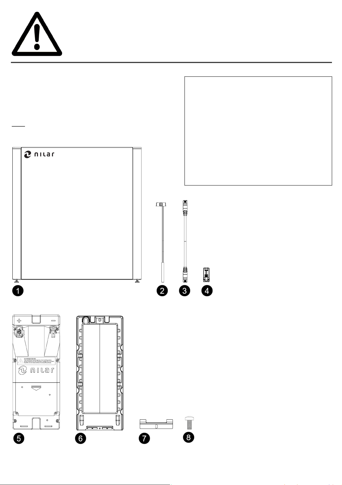
SCOPEOFSUPPLY
Thefollowingcomponentsarepartoftheproductdelivery.
Note! For illustraƟve purposes, the components are not depicted
to scale!
Importantinformaon
Readcarefully
Keepthisinformaonforfurtherreference
❶ Cabinetassembly(1unit)
❷ Ambienttemperaturesensor(1unit)
❸ Communicaoncables(3unitsincl.1spare)
❹ 120ΩCANterminaonplug(1unit)
❺ Nilarbaerypacks(4units)
❻ Insulaontrays(4units)
❼ Baeryholders(4units)
❽ Screwsforbaeryholders(4units)

PRODUCTREGISTRATION
Inordertoobtainandclaimfullwarrantyfortheproduct,the
NilarHomeBoxmustberegisteredontheNilarproductregistra‐
onwebpage(hps://www.nilar.com/product‐registraon/).As
analternavetheQR‐codebelowcanalsobeusedfordirect
accesstothewebpage.Regardingthecompletewarrantycondi‐
onsindetail,pleasecontactyourauthorizedlocalNilarrepre‐
sentave.
SERIALNUMBER
ForregistraontheserialnumberoftheNilarHomeBoxis
needed.TheserialnumbercanbefoundontheNilarlabels.
Thelabelsareplacedinfour(4)differentlocaonsoftheNilar
HomeBox.Ononesideofthesideplates❶,asalosesckerin
theplascpocketforthequickguide❷,onthetopplatebelow
thecoverlid❸andonthebackplate❹.
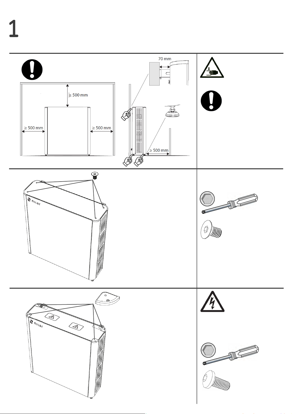
1
2
3
HX4
x 4
x 4
HX4
Ensureappropriatespaceforthe
HomeBox.
Ifrequired,adjustthesupport
legsoftheHomeBoxtolevel.
Unscrewandremovethecorner
tops.
Unscrewandremovethecover
lid.
PLEASE READ THE
WARNING STICKERS ON
THE TOP PLATE BEFORE
PROCEEDING
DO NOT ATTACH THE HOME
BOX TO THE WALL UNTIL
INSTALLATION HAS REACHED
STEP 21 IN THIS
INSTALLATION GUIDE

4
5
6
Slidethefrontplateupwardsto
unhookitandliitthereaer
outwardsandoff.
Slidethesideplateupwardsto
unhookitandliitthereaer
outwardsandoff.
Repeatprocedurefortheside
plateontheoppositeside.
Tiltthetopplateupwardsand
liitoff.
7
9
x 4
HX4
UnscrewandremovetheBMS
cover.
8
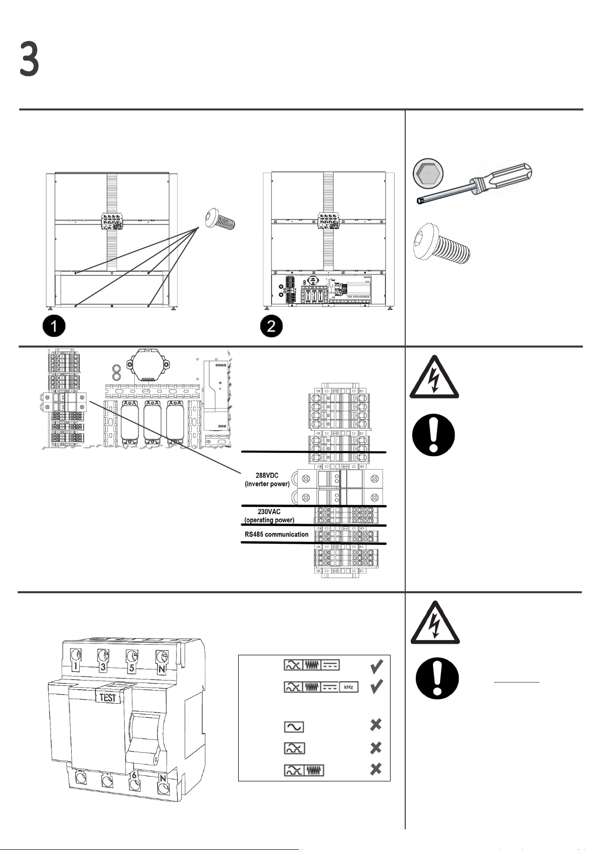
AlwaysinstallatypeBorB+
(≤30mA)ResidualCurrent
Device(RCD).IfanRCDofanot-
hertype(AC,AorF)isalready
installedbetweengridandin-
verter,itneedstobereplaced
withanRCDoftypeBorB+.
TypeB
TypeB+
____________________________
TypeAC
TypeA
TypeF
GENERAL CAUTION IS
REQUESTED WHEN
WORKING WITH THE BMS
IF THE HOME BOX IS IN-
STALLED TOGETHER WITH A
KOSTAL INVERTER WITH ITS
IN-BUILT TYPE B RCD (IΔn
=6mA) ACTIVATED, THIS
INSTALLATION STEP IS NOT
APPLICABLE

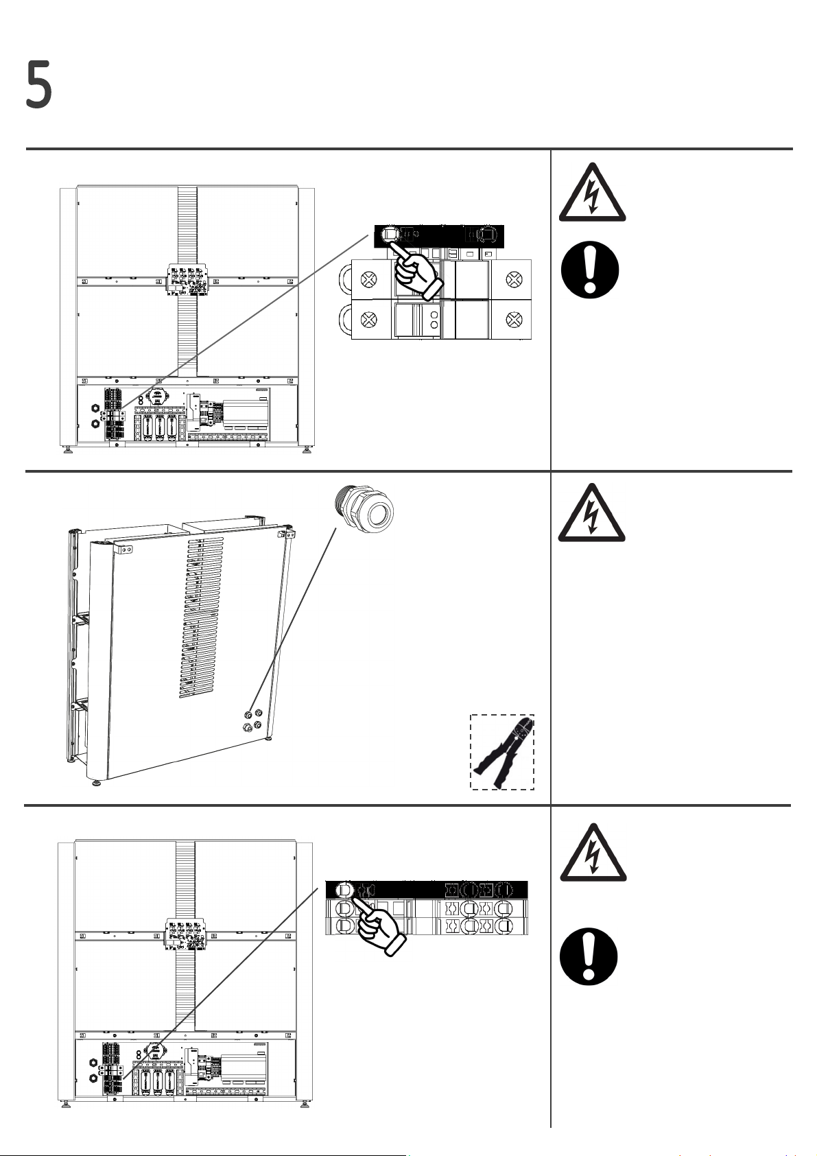
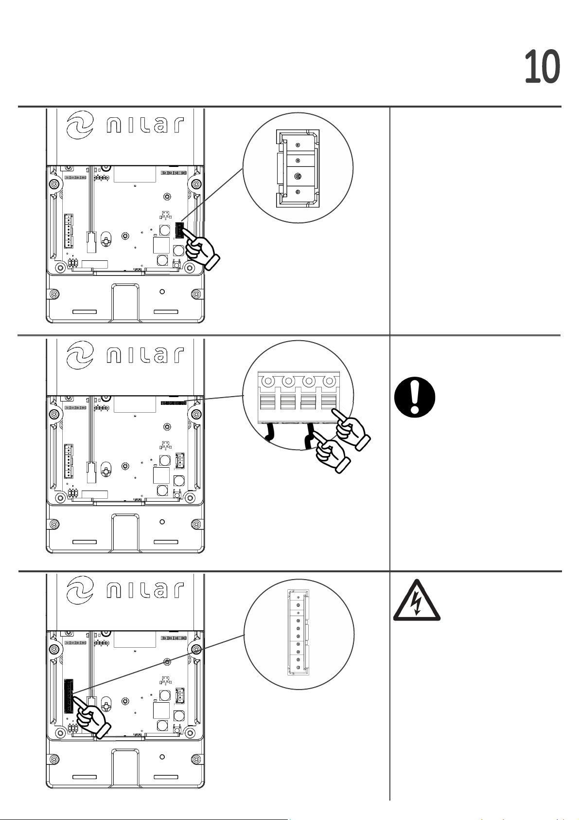
Posive(+)wireofpower
cable(s)connectstothefuse
marked’F1’oftheNilarBMS.
10
11
12
Routethe288VDCsystempower
cable(s)fromtheinverter
throughthelowerrightcable
glandlocatedonthebacksideof
theNilarHomeBox.
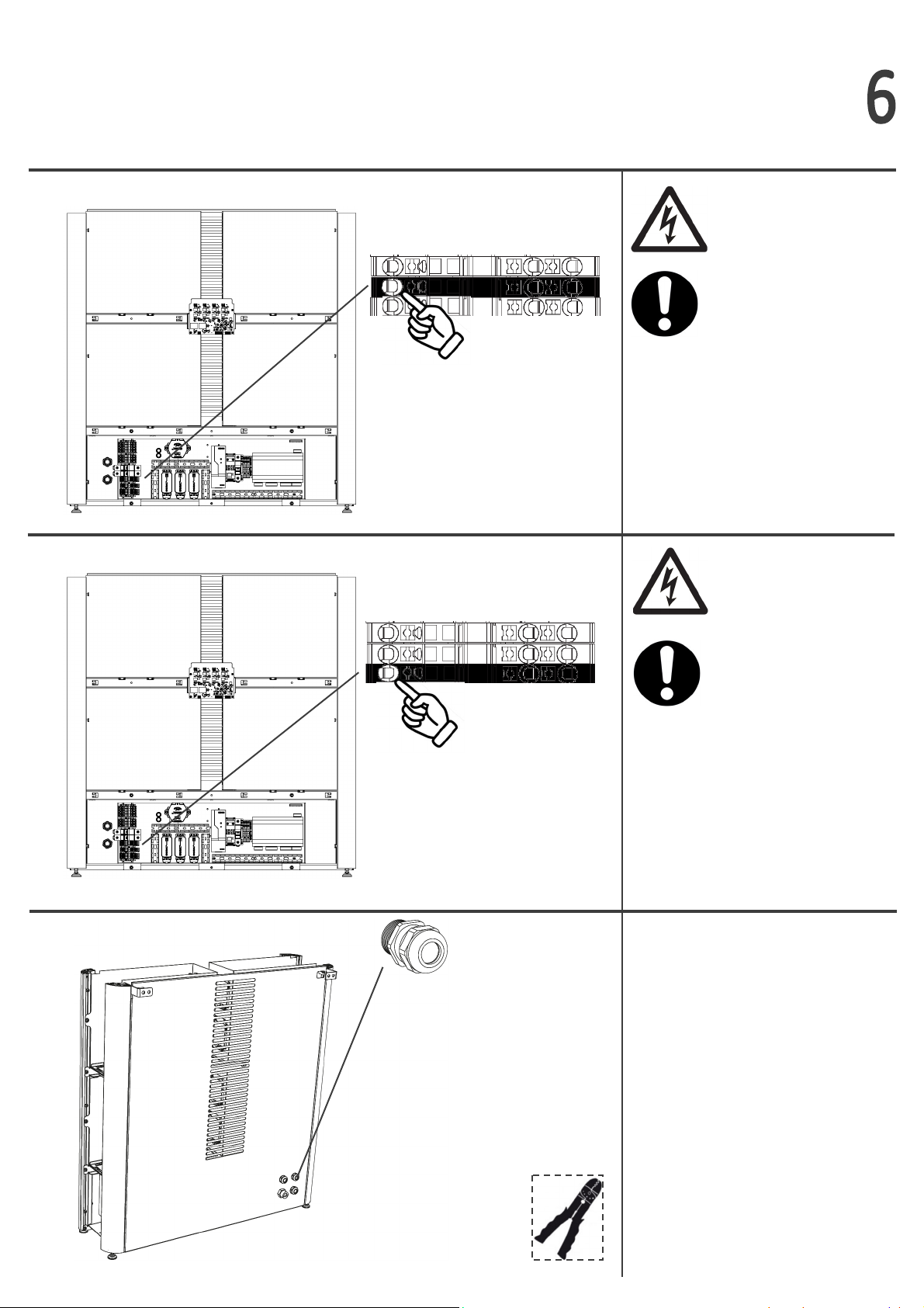
Negave(-)wireofpower
cable(s)connectstothefuse
marked’F2’oftheNilarBMS.
CONDUCTOR CROSS-SECTION
MUST BE 6mm2 (Cu)
THE INVERTER MAY STILL
PROVIDE HAZARDOUS
VOLTAGE AND RESIDUAL
ENERGY, ALTHOUGH IT IS
SWITCHED OFF OR MAY
APPEAR SWITCHED OFF
THE POSITIVE (+) WIRE
OF THE INCOMING
POWER CABLE(S) MUST
ALWAYS BE EXTERNALLY
PROTECTED BY A 25A
MCB/FUSE
CONDUCTOR CROSS-SECTION
MUST BE 6mm2 (Cu)
THE NEGATIVE (-) WIRE
OF THE INCOMING
POWER CABLE(S) MUST
ALWAYS BE EXTERNALLY
PROTECTED BY A 25A
MCB/FUSE
288VDC,posive
288VDC,negave
PH2
WS
PH2
Thelivewireoftheoperang
powercableconnectstothe
terminalmarked’1’oftheNilar
BMS.
Routethe230VACoperang
powercablethroughtheupper
lecableglandlocatedonthe
backsideoftheNilarHomeBox.
Nilarrecommendsthataswitch
isinstalledfortheoperang
powercable,preferablyinthe
vicinityoftheNilarHomeBox.
Theprotecveearth(PE)wireof
thepowercable(s)istobe
connectedtotheterminal
marked‘PE’ oftheNilarBMS.
CONDUCTOR CROSS-SECTION
MUST BE 6mm2 (Cu)
288VDC,protecveearth
230VAC,live
14
13
15
WS
CONDUCTOR CROSS-
SECTION MAX 2,5MM2 (CU).
FUSE/MCB: C10A
(MIN. 6A AND MAX. 10A,
CHARACTERISTICS: B, C, D
OR K ARE POSSIBLE)
Theneutralwireoftheopera-
ngpowercableconnectstothe
terminalmarked’2’oftheNilar
BMS.
CONDUCTOR CROSS-SECTION
MAX 2,5mm2 (Cu)
Theprotecveearth(PE)wireof
theoperangpowerconnectsto
theterminalmarked’PE’ofthe
NilarBMS.
CONDUCTOR CROSS-SECTION
MAX 2,5mm2 (Cu)
Routetheinverter
communicaoncablethrough
theupperrightcablegland
locatedonthebacksideofthe
NilarHomeBox.
230VAC,neutral
230VAC,protecveearth
16
17
18
WS

AachtheRS485signalwiresto
thecorrelangterminalsofthe
NilarBMS.
①SignalA: Terminal7
②SignalB: Terminal8
③Signalgnd:EmptyPEterminal
CONDUCTOR CROSS-SECTION
MAX 2,5mm2 (Cu)
Connectaninternetcabletothe
RJ45portonthebacksideofthe
cabinet.
20
21
19
FixtheHomeBoxbyaaching
themounngbracketswithtwo
(2)screwseachontoa
stablewall.
THE HOME BOX MUST
ALWAYS BE FIRMLY
ATTACHED TO A STABLE
WALL. TYPE AND LENGTH OF
SCREWS DEPEND ON
MATERIAL IN WALL AND THE
SCREWS ARE NOT SUPPLIED
WITH NILAR HOME BOX.
THE NILAR HOME BOX
REQUIRES A STABLE
INTERNET CONNECTION FOR
TECHNICAL SUPPORT AND
FULFILLING OF WARRANTY
CONDITIONS
①
②
③
22
23
24
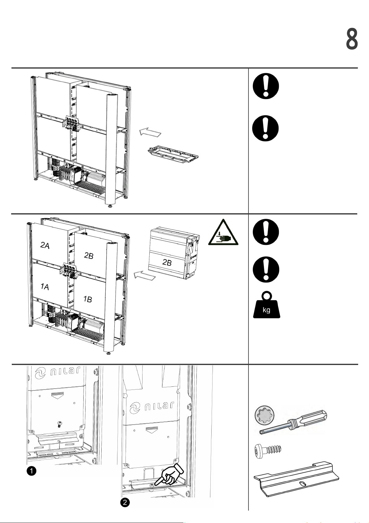
Placeallfour(4)insulaontrays
inallfour(4)shelfopeningsof
theHomeBox.
NEVER EVER INSTALL
BATTERY PACKS WITHOUT
INSULATION TRAYS
ID-MARKING ON BATTERY
PACK MUST MATCH
ID-MARKING IN BATTERY
SHELF SLOT OF HOME BOX
IT IS RECOMMENDED TO USE
LIFTING AIDS
Carefullyli/slideallfour(4)
baerypacksintotheir
dedicatedshelfslots.
REMOVE BOTH LIFTING
STRAPS FROM THE BATTERY
PACKS
Fixthebaerypacktothe
insulaontraywiththescrew.
Repeatforallbaerypacks.
TX20
x 4
x 4
ENSURE THAT NO CABLES
ARE SQUEEZED IN-BETWEEN
THE SHELVES AND THE
INSULATION TRAYS
TX20
x 2
26
27
25
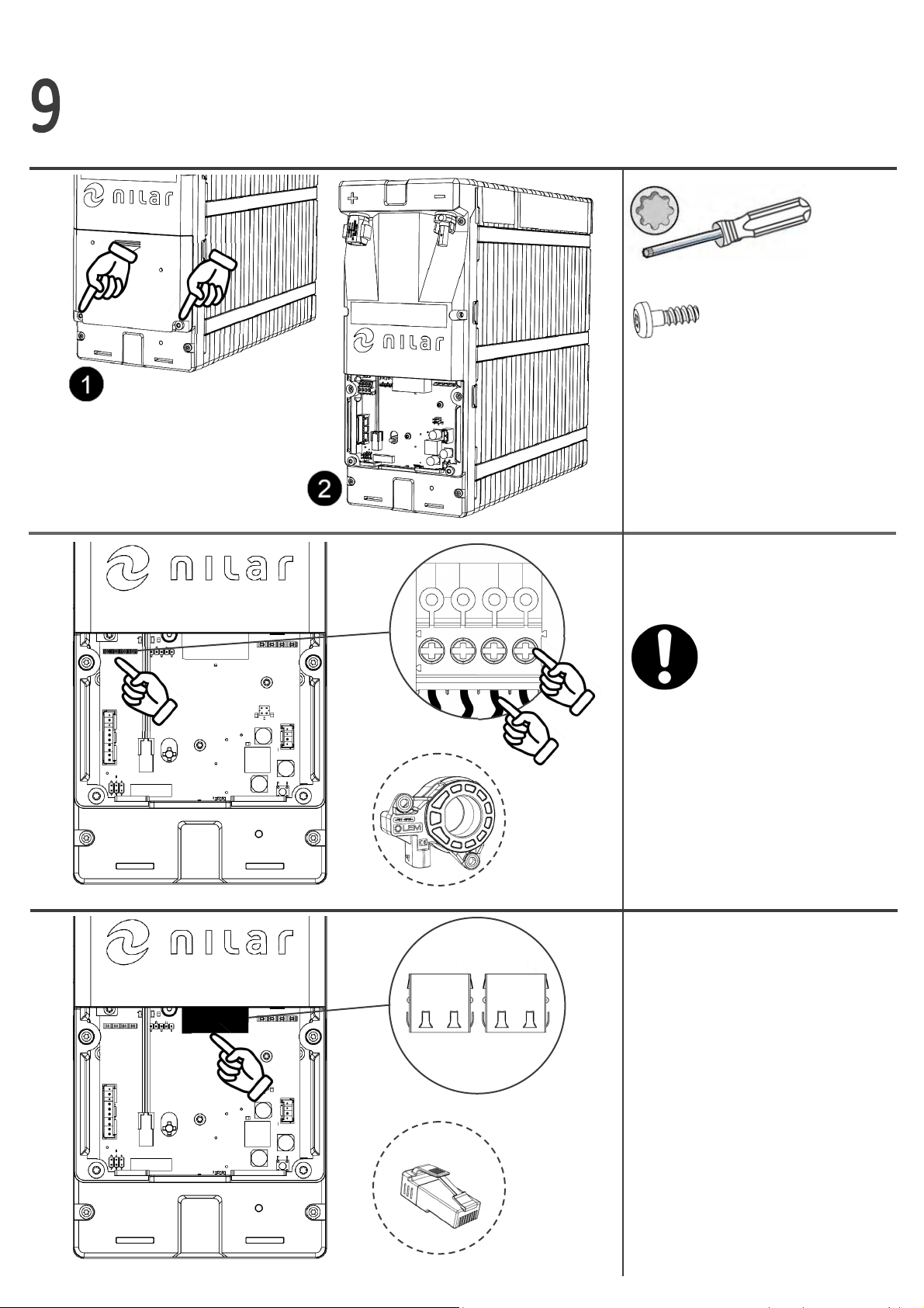
BE CAREFUL TO CONNECT
THE CURRENT SENSOR
CONNECTORS WITH THE
CORRECT ORIENTATION. THE
CLAMPING SCREWS ①
MUST BE VISIBLE ON THE
FRONT SIDE AND THE
CABLES ②MUST POINT
DOWNWARDS.
①
② Connectthecurrentsensor
cableconnectorstothe
baerypacks’1B’and’2B’.
Currentsensor
Connectthepre-routed
communicaoncablefromBMS
tobaerypack’1A’(RJ45).
Connecttheinterpack
communicaoncablesbetween
baerypack’1A’and’2A’,
between’2A’and’2B’
(pre-routed),andbetween
’2B’and’1B’.
Insertthe120Ωterminaonplug
inthelastemptyCAN
conneconofbaerypack’1B’.
120Ωt.plug
29
28
30
Connectallthepre-routedfan
cablestoallbaerypacks.
Connectallthepre-routed
24VDCpowersupplycable
connectorstoallbaerypacks.
①
②
Connecttheambient
temperaturesensorcableto
baerypack’1A’.
ALWAYS LET THE
AMBIENT TEMP. SENSOR
CABLE HANG DOWN
FREELY. NEVER EVER LET
IT TOUCH THE BATTERY
PACK MODULES.
BE CAREFUL TO CONNECT
THE 24VDC CONNECTORS
WITH THE CORRECT
ORIENTATION. THE CLAM-
PING SPRINGS ①MUST BE
VISIBLE ON THE FRONT SIDE
AND THE CABLES ②MUST
POINT DOWNWARDS.

Connecttheposive(+)chassis
connectorofbaerypack‘1A’to
thenegave(-)chassis
connectorofbaerypack‘1B’by
usingthepre-routedinterpack
powercablelocatedbeneaththe
baerypackshelf.
Connectthepre-routednegave
(-)powercableintothenegave
(-)chassisconnectorofbaery
pack‘1A’.
CHECK THAT THE FUSES
ARE NOT ACTIVATED , SEE
INSTALLATION STEP #38
32
33
31
Le
side
Right
side
Le
side
ConnectalltheETPU-cable
connectorswithallthe
pre-routedETSU-cable
connectorsforeachbaery
pack.
Installthecoverlidsbackonall
thebaerypacksandcheckthat
allconnectedcablesarerouted
throughthecableentry①.
①

Connectthepre-routedposive
(+)powercableequippedwith
thecurrentsensorandconnect
ittotheposive(+)chassis
connectorofbaerypack‘1B’.
Placethecurrentsensorpartly
insidetheshelfbeneath.
THE TEXT MARKING
“LEM” ①OF THE CURRENT
SENSOR MUST ALWAYS
POINT TOWARDS THE
POSITIVE (+) CHASSIS
CONNECTOR.
Connectthepre-routedfuse
equippednegave(-)power
cableintothenegave(-)
chassisconnectorofbaery
pack‘2A’.
35
34
36
Connecttheposive(+)chassis
connectorofbaerypack‘2A’to
thenegave(-)chassis
connectorofbaerypack‘2B’by
usingthepre-routedinterpack
powercablelocatedbeneaththe
baerypackshelf.
Le
side
Le
side
Right
side
Right
side
①
THE CABLE IS A TWO (2)
CABLE ASSEMBLY EQUIPPED
WITH A FUSE. DO NOT
DETACH THE CABLE
ASSEMBLY.
THIS CABLE IS ATTACHED TO
THE PREVIOUSLY INSTALLED
CABLE BY CABLE TIES.
DO NOT DETACH CABLES
FROM EACH OTHER.

Removetheadhesivetapeover
theblowfuses(288VDC),
acvatethefusesbyclosingthe
hatches.
SwitchtheMCB(24VDC)forthe
operaonpowertoposion
’ON’.
38
37
Connectthepre-routedfuse
equippedposive(+)power
cableequippedwiththecurrent
sensorandconnectittothe
posive(+)chassisconnectorof
baerypack‘2B’.
Placethecurrentsensorpartly
insidetheshelfbeneath.
Fuses
MCB
THE TEXT MARKING
“LEM” ①OF THE CURRENT
SENSOR MUST ALWAYS
POINT TOWARDS THE
POSITIVE (+) CHASSIS
CONNECTOR.
①
Right
side
THE CABLE IS A TWO (2)
CABLE ASSEMBLY EQUIPPED
WITH A FUSE. DO NOT
DETACH THE CABLE
ASSEMBLY.
THIS CABLE IS ATTACHED TO
THE PREVIOUSLY INSTALLED
CABLE BY CABLE TIES.
DO NOT DETACH CABLES
FROM EACH OTHER.

ASSEMBLE THE NILAR HOME BOX CABINET IN THE
REVERSE ORDER OF HOW IT IS DESCRIBED IN
INSTALLATION STEP 2 – 7 AND CHECK THE INVERTER
MANUFACTURER’S INSTRUCTIONS FOR FURTHER
INFORMATION BEFORE TAKEN INTO OPERATION.
39
40
HAVE ALL THE PREVIOUSLY STATED SAFETY WARNINGS AND CAUTIONS BEEN
FOLLOWED?
IS THE INVERTER POWER AND THE PROTECTIVE EARTH CONNECTED
CORRECTLY TO THE NILAR HOME BOX?
IS THE OPERATING POWER INSTALLED CORRECTLY?
IS THE COMMUNICATION CONNECTION OF THE INVERTER MADE
CORRECTLY?
IS A STABLE INTERNET CONNECTION ESTABLISHED?
IS THE NILAR HOME BOX FIRMLY ATTACHED TO A STABLE WALL?
ARE THE INSULATION TRAYS AND BATTERY PACKS INSTALLED CORRECTLY?
ARE ALL EIGTH LIFTING STRAPS REMOVED FROM THE BATTERY PACKS?
ARE THE FUSES INSERTED AND THE MCB ACTIVATED?
PLEASE VERIFY THAT ALL THE
LISTED CHECKPOINTS ARE
CARRIED OUT AS PREVIOUSLY
DESCRIBED
41
PLEASE HAND OVER THE ENCLOSED ’END CUSTOMER
LETTER’ TO THE CLIENT

NilarAB
Stockholmsvägen116B,6tr
SE‐18730Täby,Sweden
This manual suits for next models
2
Table of contents
Other Nilar Camera Accessories manuals

Popular Camera Accessories manuals by other brands

ORION TELESCOPES & BINOCULARS
ORION TELESCOPES & BINOCULARS StarBlast II installation instructions

Sachtler
Sachtler Cine 7 + 7 HD manual

Acebil
Acebil I-605LAX Operation manual

COLBOR
COLBOR CL100-M user manual

Black & Decker
Black & Decker BT2000 instruction manual

Bioenno Power
Bioenno Power BLF-4830A user manual


