The
400 ft
magazines
fQr
black-and-whit
e
mm
suppli
ed
her
etQfQre
hav
e
proved
tQQ
small
fQr
the
variQus
CQ
IQur emulsiQns
wh
ich
ar
e '
available
nQwa-
days,
si
nce
cQIQur film emulsiQn is a
little
thick,er.
than
black
-
and-white
.
Th
e
new
400 ft ma<gazine
fQr
th
e ARRIFLEX 35,
de
'
sign
ed
with
this
fact
in
mind,
has
a cQrresPQndingly
greater-ca
p
acity
and
accepts
th
e full 400 ft r,
ee
ls
Qf
CQlour
fHm
Qr
Qf
500 ft
black-and-white
film.
This
means
a
regul
,
ar
300 m
black-.
and-white
film rQll
can
be
half
ed
and
IQaded
intO'
this
magazin
e,
giv
!
ing
51/ 2
minut
e,s
Qf
shQQting
tim
e
(400
ft l
oads
41
1z
minutes).
Like
all
pr
eviQus mQdels,
the
new
ARRIFLEX 35
magazin
e
can
be
IQaded Qnly
with
films
wound
emuls
iQn
side in
on
plastic
cores
with
slot
or lug.
Th
e QperatiQns desc
rib
ed in
the
fQllQw
i
ng
instructiQns
shQuld be pracbiced
first
in
daylight
and
with
blank
film
until
yQU
are
perfectly
familiar
with
the
'whQle QperatiQn. LQading
in
the
darkrQQm
Qr
the
changing
bag
with
une
xpos
,
ed
film
will
then
be
much
eas
,
ier
an.d
can
be
performed
quickly
and
without
unn
ec
essary
de
l
ay
.
* * *
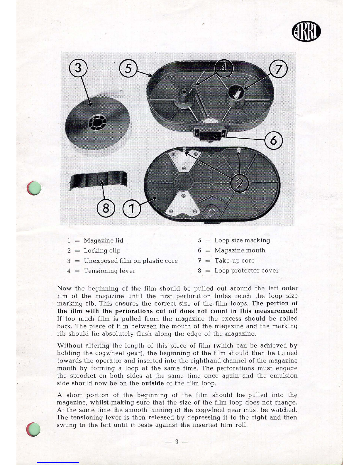
F
irst
remQve
th
e
lid
Qf
th
e
magazin
e by
turning
the
locking
bar
to
the
left
and
gripping
the
lid
Qn
the
small
proj
e
ction
above
the
bar.
Then
fold
it
forward
s
and
lift
if
frQm
its
guid
e
s.
Place
the
magazine
on
a
table
so
that
th
e
cogw
he
el
ge
ar
PQints
towards
you
.
Place
the
film peel
on
th
e left
besid
e
t
he
magazine
so
that
the
film roHs off
in
a
c\ockwis
'e
direcHon
,
and
the
be<ginnin<g
points
to
th
e
right
, tQwards
th
e
magazine
. The film
should
n
QW
be
trimm
ed
in
th
e
following
way:
-Us·e the
templ
'
ate
s'Upp
lued
with
ev
e
ry
cameva
and
cut
off
th
e
perfQrations
Qn
bo
th
side
,s up
to
apprQximately
the
20th
ho
le
Qr
'
SO'
th
at
fir'
st
twO'
perforatiQn
ho
l'es
of
the
film
are
cut
open,
Then
the
trimmed
film
leader
is
tak
en
insid
e
the
op
en maga2'2ine
and
insle
rted
from
insid
e thrQugh
th
e f
ee·
d
sprocke
t
until
it
pTotrudes
outsid
e
through
the .left film
chann
e
l.
This
thr
e
ading
must
be
done
'
so
that
the
film is
guid
ed
cQmpl'etely
straight
an.d
paralle
l
to'
t
he
wall
Qf
th
e
magazine
in
Qrder
to'
all
Qw
the
peifforatiQns
to'
e
nga
'ge
th
e
sprocket
's,imultaneQus.ly
Qn
both
s,
id
e
s.
This
can
be
fad
libated
by
ge
ntly
turning
th
e
cogwhe
·e
l geaT
by
'
hand.
Now
the
te
nsioning
Ie
ver
inside
th
e
magazin
e shQuld
be
mov
,
ed
towards
th
e
right
until
it
snaps
'i
n
besi
'
de
the
take-up
CQr
,e. The film
ro
ll
can
now
be
slip
ped
Qn
the
left
-
hand
spindl
e.
Wh
en
cor
es
with
a sl
Qt
ar
e
used,
the
spring
of
th
e
spindle
will
snap
in
autQmatically
after
on
e
single
turn
of
the
roll.
If
'a
CQT
,e
wi
th a
lug
is
employed
th
e
corr
e
ct
pl
acing
Qf
th
e l
ug
in
~h
e
sIot
sh
ou
ld
be
watched
ca
.
refully,
since,
in
this
cas
'e,
the
spring
does
not
snap
in
.
Aft
er
inserting
th
e film
roll
into
bhe
magazine
the
film
shou
ld lie
perf
,e
ctly
flat
'
esp
eci'
ally
ne
ar
the
cor
e
and,
furthermQ're,
it
should
be
wound
tightly
.
-
2-