Niles IRP-2+ Troubleshooting guide
Other Niles Extender manuals
Niles
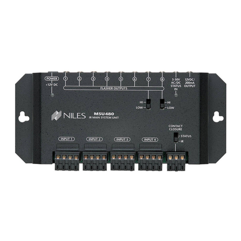
Niles MSU480 User manual
Niles
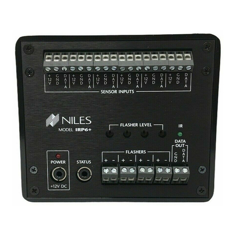
Niles IRP6+ User manual

Niles
Niles MSU480 Original operating instructions
Niles
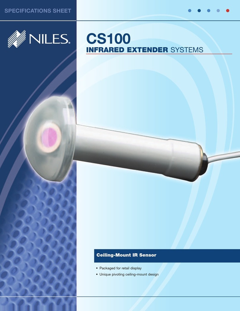
Niles CS100 User manual
Niles
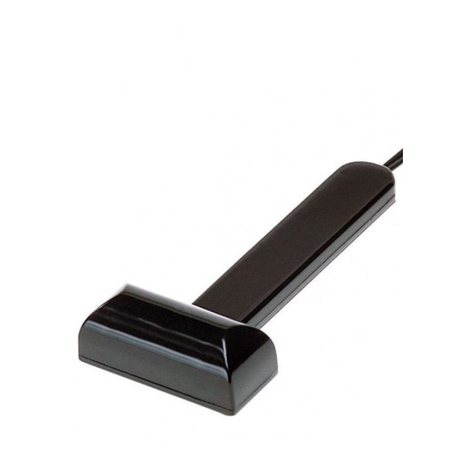
Niles IRB1 User manual

Niles
Niles IRH610 User manual

Niles
Niles ZR-KE User manual
Niles
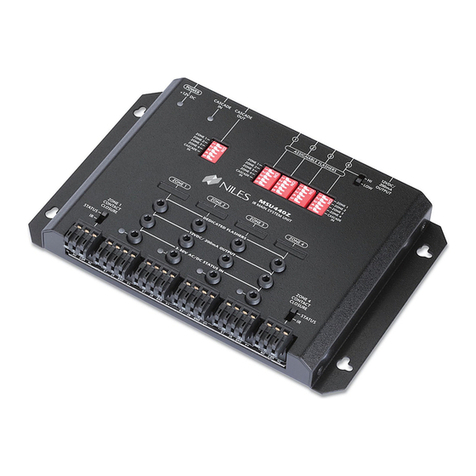
Niles MSU440Z User manual
Niles
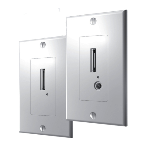
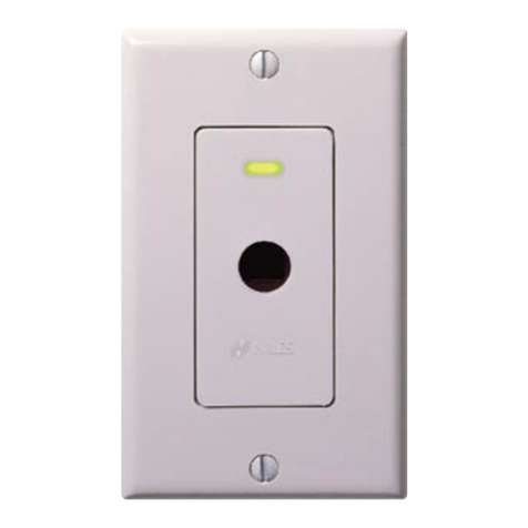
Niles Extender System iWare ES1 User manual
Niles
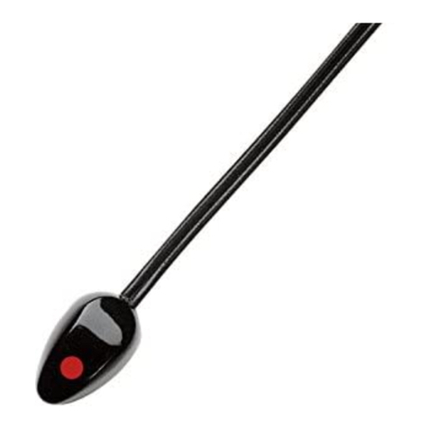
Niles Wall-Mount IR Sensor WS110R User manual
Niles
Niles MF1VF User manual

Niles
Niles IRZ6+ INTELLIPAD User manual
Niles
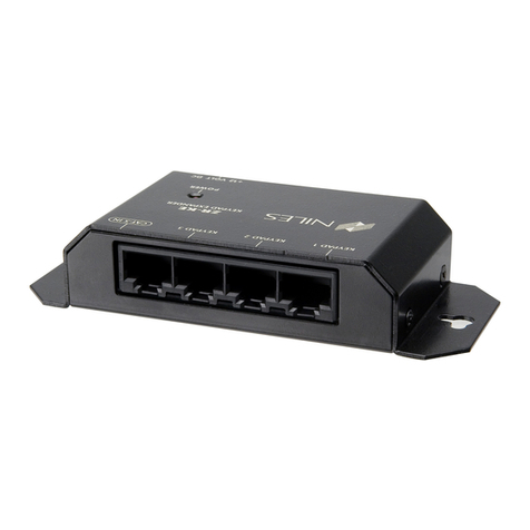
Niles ZR-4 SERIES User manual
Niles
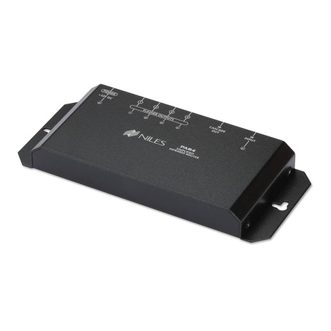
Niles PAR4 User manual
Niles
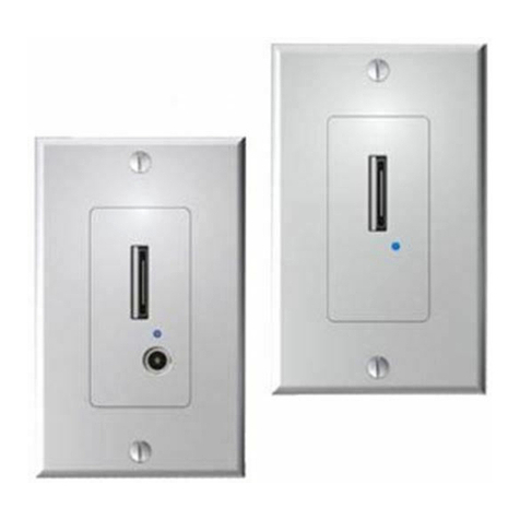
Niles iWare ES1 User manual
Niles
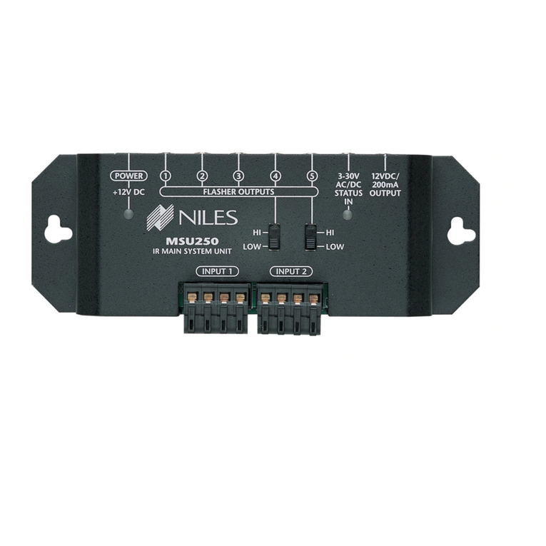
Niles MSU250 User manual
Niles
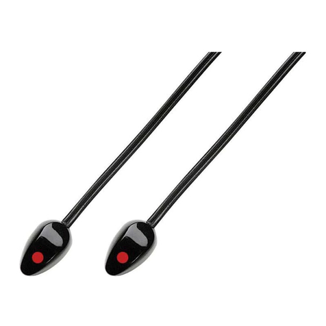
Niles MF2VF User manual
Niles
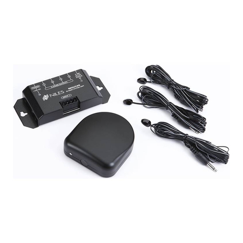
Niles RCA2 User manual
Niles
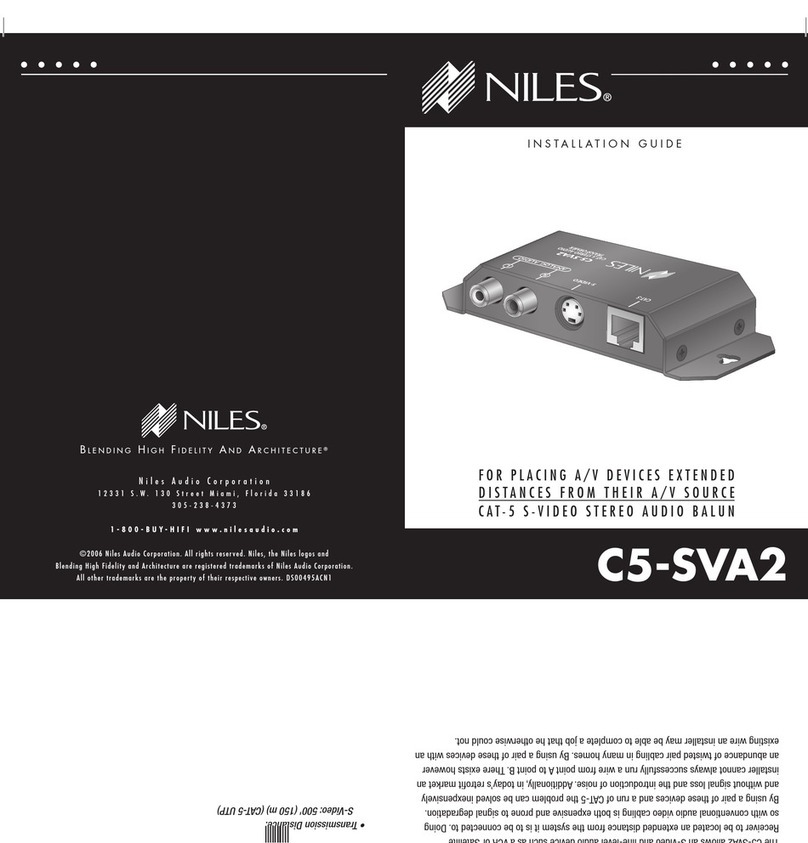
Niles C5-SVA2 User manual
Niles
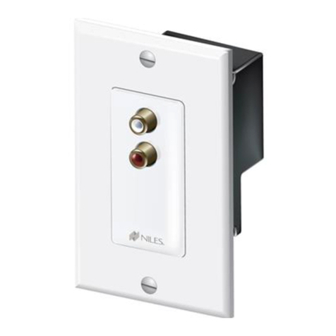
Niles C5-A2WM User manual
Popular Extender manuals by other brands

foxunhd
foxunhd SX-AEX01 operating instructions

TERK Technologies
TERK Technologies LFIRX2 owner's manual

Devolo
Devolo Audio Extender supplementary guide

Edimax
Edimax EW-7438RPn V2 instructions

Shinybow USA
Shinybow USA SB-6335T5 instruction manual

SECO-LARM
SECO-LARM ENFORCER EVT-PB1-V1TGQ installation manual
