Ningbo Sun Earth TPB Series User manual
Installation
Installation
Installation
InstallationManual
Ma nual
Manual
ManualFor
Fo r
For
ForThe
Th e
The
TheSun
Su n
Sun
SunEarth
Ea rth
Earth
EarthT
T
T
TP
P
P
PB-Series
B- Series
B-Series
B-Seriesof
of
o f
ofSolar
So lar
Solar
SolarPhotovoltaic
Ph otovoltaic
Photovoltaic
PhotovoltaicModules
Mo dules
Modules
Modules
Page
Page
Page
Page1
1
1
1of
of
o f
of8
8
8
8
INSTALLATIONMANUAL
FORTHESUNEARTHTPB—SERIES
OFSOLARPHOTOVALTAICPOWERMODULES
1、Introduction
1.1NingboSolarElectricPowerCo,LtdcommencedmanufacturingSunEarthsolar
cellsandmodulesin1978.Formorethantwentyyearscompanyprovidesthe
highestqualityMono-crystallineSiliconmodulesinarangeofsizesdesignedto
meettherequirementsoftheusersdomesticandabroad.Ourcompanyhas
advancedtechnologyandhighqualityproducts.Theproductsconformtocriterion
ofIEC61215,andhaspassedISO9001-2000、CEandTUVcertification.
1.2SolarModules
Themodulesconsistofaseriesofelectricallyinterconnectedcrystallinesilicon
solarcells,whicharepermanentlylaminatedwithinspecialsolar
EVA
and
encapsulatedbetweenatemperedglasscoverplateandTPT.Theentirelaminate
issecuredwithinananodizedaluminumframe,whichnotonlysupplystructural
strength,butalsosupplyelectricalinsulationandcertainchemicalprotection.
Thereforemodulesarelonglifeandreliable.
1.3Applications
SUNEARTHsolarmodulesisahigh-efficiency、long-lifedirectcurrentpower
source.Themodulesareidealtoremotemountainousarea、trafficlight、water
pumps、long-distancetelecommunicationsystemsandelectricitystation.
1.4
1.4
1.4
1.4Note
No te
Note
Note
1.4.1Becauseofhighvoltage、highpowerofthesolararraywhichismadeofmany
modules,pleasetakecareofthesafetyofinstallationpersonnel.
To
reducethe
riskofelectricalshockorburns,modulesmaybecoveredwithopaquematerial
(e.g.,Blackcloth)duringinstallation.
1.4.2Installationpersonnelmustbeauthorized.Duringinstallationfollowoperating
requirementtoavoidshocksorburns.Donottouchliveterminalswithbarehands.
Useinsulatedtoolsforelectricalconnections.
1.4.3Beforeinstallation,inordertomakesuretherequirementsofinstallationand
check.Installationpersonnelhavetoredinstallationmanualandkindsofusing
instructionscarefully(storagebattery、chargecontroller、inverter)
1.4.4Intheprocessofinstallationandapplying,artificiallyconcentratedsunlightare
notpermittedtobedirectedonthemodulesorpanels.

Installation
Installation
Installation
InstallationManual
M anual
Manual
ManualFor
F or
For
ForThe
T he
The
TheSun
S un
Sun
SunEarth
E arth
Earth
EarthT
T
T
TP
P
P
PB-Series
B -Series
B-Series
B-Seriesof
o f
of
ofSolar
S olar
Solar
SolarPhotovoltaic
P hotovoltaic
Photovoltaic
PhotovoltaicModules
M odules
Modules
Modules
Page
Page
Page
Page2
2
2
2of
o f
of
of8
8
8
8
SiliconSolarCellModuleTPB156×156-72-PElectricalParameters
TestingCondition:AM1.5Ee=1000W/㎡T=25℃±2℃
ElectricalCharacteristics
CellPoly–CrystalSilicon
No.ofCellsandConnections72inSeries
RatedMaximumPower(W)235240245250255260265270275280285290
VoltageatPmax(Vmp)34.134.234.334.434.534.634.734.834.935.035.135.2
CurrentatPmax(Imp)6.907.027.157.277.397.527.647.767.888.008.128.24
Open-circuitVoltage(Voc)43.143.243.443.543.643.743.843.944.044.144.244.3
Short-circuitCurrnet(Isc)7.607.707.807.897.988.078.168.258.348.438.558.59
TemperatureCoefficients
Open-CircuitVoltage(Voc)-0.35%/℃
Short-CircuitCurrnet(Isc)+0.05%/℃
VoltageatPmax(Vmp)-0.4%/℃
CurrentatPmax(Imp)+0.04%/℃
Power(Pmax)-0.42%/℃
NOCT(20℃,0.8KW/m2,1m/s)45.5℃
MaximumSystemVoltage1000VDC
MaximumSeriesFuseRating16A
MaximumOver-CurrentRating16A
BypassDiodesThree15A,45V
JunctionBoxJHB-5;1000VDC;16A;IP65;
OutputCables2PfG1169;PV1-F1×4mm2
ConnectorYF-1001;1000VDC;16A;
ApplicationClassClassA
FireResistanceRatingClassC
MaximumLoadCapacity200Kg/m
2
MaximumHailDiameter@82.8Km/h25mm
AbsoluteMaximumRatings
OperatingTemperature-40to185℉/-40to+85℃
StorageTemperature-40to185℉/-40to+85℃
MechanicalCharacteristics
Dimensions1958mm×992mm×46mm
Weight23㎏
2、InstallationandOperation
2.1Onlyauthorizedandtrainedpersonnelshouldhaveaccesstothesemodules.

Installation
Installation
Installation
InstallationManual
M anual
Manual
ManualFor
F or
For
ForThe
T he
The
TheSun
S un
Sun
SunEarth
E arth
Earth
EarthT
T
T
TP
P
P
PB-Series
B -Series
B-Series
B-Seriesof
o f
of
ofSolar
S olar
Solar
SolarPhotovoltaic
P hotovoltaic
Photovoltaic
PhotovoltaicModules
M odules
Modules
Modules
Page
Page
Page
Page3
3
3
3of
o f
of
of8
8
8
8
Thesysteminvolveselectricity,andcanbedangerousifthepersonnelarenot
familiarwiththeappropriatesafetyprocedures.
2.2Duringinstallation,pleasetakecareofglass,whichmaybescratchedandhit.
2.3Solarmodules‘Installationpositionandrangemanner(inseries,inparallel)on
rackshouldaccordingtoconstructionaldrawing(rackdevicedrawingandpower
connectiondrawing).Solararraytiltangleshouldbeadjustedaccordingto
regulation.
Note:
Note:
Note:
Note:Minimum
M inimum
Minimum
Minimum100
1 00
100
100mm
m m
mm
mmspacing
s pacing
spacing
spacingbetween
b etween
between
betweenthe
t he
the
themodule
m odule
module
moduleframes
f rames
frames
framesand
a nd
and
andsurface
s urface
surface
surfaceof
o f
of
of
the
the
the
themounting
m ounting
mounting
mountingplate
p late
plate
plateor
o r
or
orground
g round
ground
groundis
i s
is
isrequired
r equired
required
requiredto
t o
to
toallow
a llow
allow
allowair
a ir
air
airto
t o
to
tocirculate
c irculate
circulate
circulate
behind
behind
behind
behindthe
t he
the
themodule.
m odule.
module.
module.
Installationstructurerecommendation(Forreferenceonly)
1.AngleSteel40mm×40mm2.BoltM16×353.NutM164.FlatM16
MODULE BACK SURFACE DRAWING
TPB156×156-72-P
MOUNTING HOLE
6 8.5
Grounding Hole
6 8.5
MOUNTING HOLE
4.5mm
Installation
Installation
Installation
InstallationManual
M anual
Manual
ManualFor
F or
For
ForThe
T he
The
TheSun
S un
Sun
SunEarth
E arth
Earth
EarthT
T
T
TP
P
P
PB-Series
B -Series
B-Series
B-Seriesof
o f
of
ofSolar
S olar
Solar
SolarPhotovoltaic
P hotovoltaic
Photovoltaic
PhotovoltaicModules
M odules
Modules
Modules
Page
Page
Page
Page4
4
4
4of
o f
of
of8
8
8
8
5.Spring-flatM166.AngleSteel40mm×40mm7.BoltM16×16
8.NutM69.FlatM610.Spring-flatM6
11.
AngleSteel40mm×40mm12.AngleSteel40mm×40mm
13.ThoughSteel100mm
2.4Themoduleshavebeenevaluatedformountingusingthe6providedmounting
holes(Diameter8.5mm)intwosideoftheframe,foramaximumpositiveor
negativedesignloadingof2400Pa.
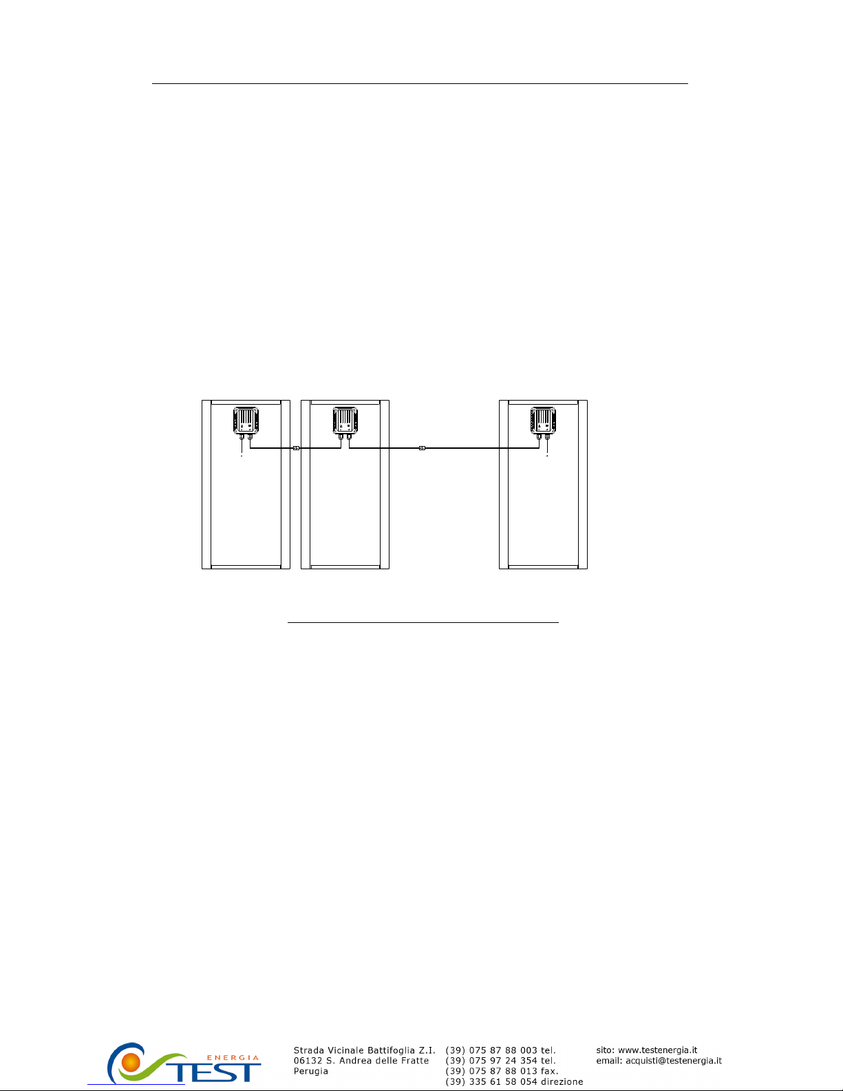
2.5Theoutputwireofthesolararray、blockingdiode、bypassdiodemustbe
connectedcorrectly(bypassdiodehasconnectedinmodule).
TPB156×156-72-P
INSERIESCONNECTIONDRAWING
2.6Themoduleframeismadeofanodizedaluminum,andthereforecorrosioncan
occurifthemoduleissubjecttoasaltwaterenvironmentwithcontacttoarackof
anothertypeofmetal.Ifrequired,PVCorstainlesswasherscanbeplaced
betweenthesolarmoduleframeandsupportstructuretopreventthistypeof
corrosion.
2.7ThesolarmoduleframemustbeattachedtoasupportstructureusingM6
stainlesssteelhardwareinaminimumofsixplacessymmetricalonthesolar
module.
2.8modulesupportstructuresshouldbewindrated(systemdesign).
2.9Ifseveralmodulesareconnectedinseries,themax.numberofmodule(N)=Vmax
system/Voc(atSTC).
2.10Ifseveralmodulesareconnectedinparallel,themax.numberofmodule=2.
IP65 1000VDC 4mm
1
2
2
1
2
2
2
1
IP65 1000VDC 4mm
2
1
IP65 1000VDC 4mm
2
1
2
2
1
Installation
Installation
Installation
InstallationManual
M anual
Manual
ManualFor
F or
For
ForThe
T he
The
TheSun
S un
Sun
SunEarth
E arth
Earth
EarthT
T
T
TP
P
P
PB-Series
B -Series
B-Series
B-Seriesof
o f
of
ofSolar
S olar
Solar
SolarPhotovoltaic
P hotovoltaic
Photovoltaic
PhotovoltaicModules
M odules
Modules
Modules
Page
Page
Page
Page5
5
5
5of
o f
of
of8
8
8
8
3、Grounding
Solarpanelsshouldbegroundedindependentlyaftercompletetheinstallation,
theoperationshouldbedoneasfollowingway:
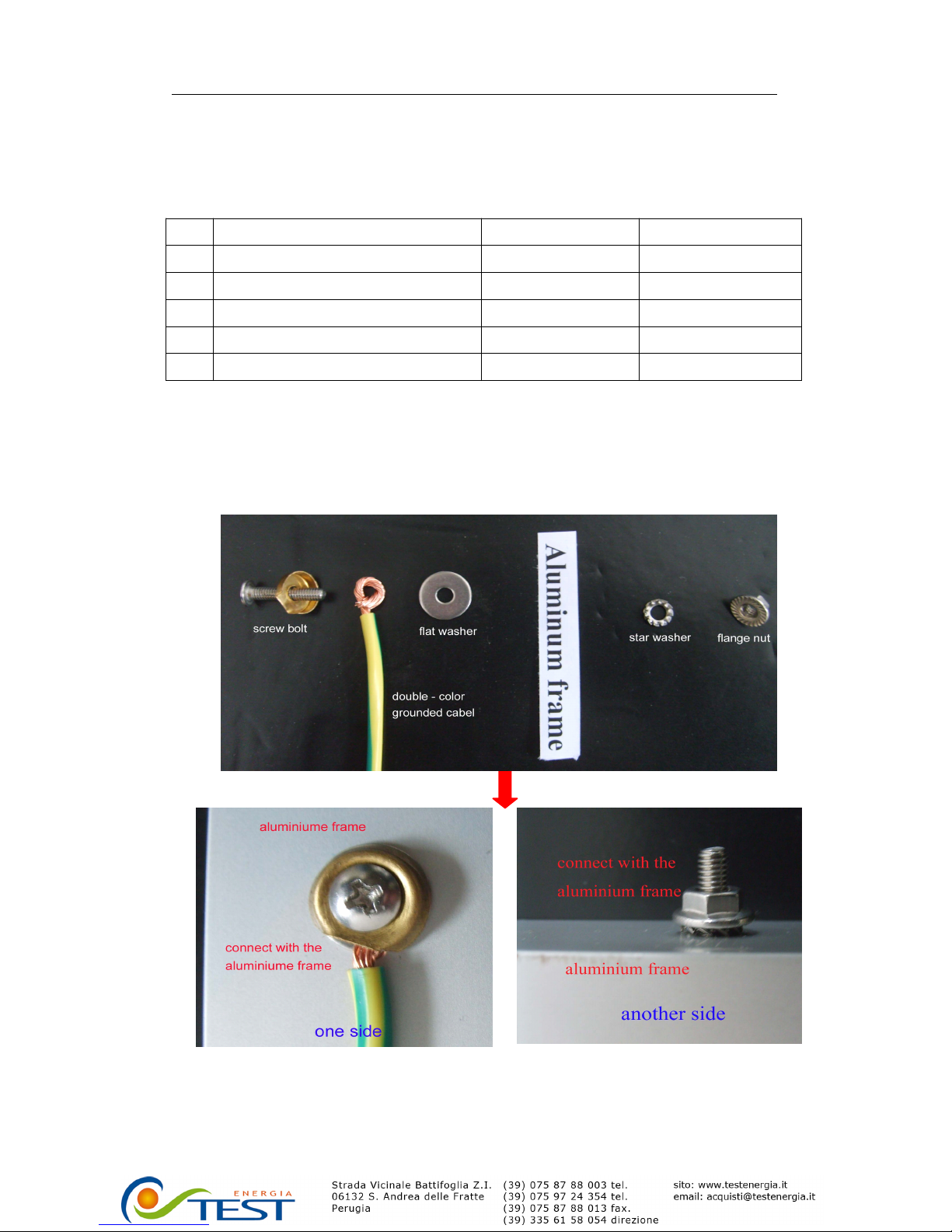
3.1Chosethecorrectgroundedconnectioncomponentsaccordingfollowingtable:
3.2Drillthestainlesssteelscrewbolt,flatwasher,starwasherandflangenutwith
exposedoneendofthedouble-colorgroundcableintothegroundingholeonthe
solarpanelsbycrossscrewdriver.Seegroundedoperationfigure
3.3
3.3
3.3
3.3Connectanotherendofthegroundcableintothespecialgroundedplatewhich
shouldbeconfirmedbeengroundedwellalready.
Grounded
G rounded
Grounded
Groundedoperation
o peration
operation
operationfigure
f igure
figure
figure
No.ItemsSpecificationRequirement
1ScrewboltM4×20mmStainlesssteel
2FlatwasherM4×14mmStainlesssteel
3Double-colorgroundedcableBVR450/750V2.5mm2
4StarwasherM4mmStainlesssteel
5FlangenutM4mmStainlesssteel
Installation
Installation
Installation
InstallationManual
M anual
Manual
ManualFor
F or
For
ForThe
T he
The
TheSun
S un
Sun
SunEarth
E arth
Earth
EarthT
T
T
TP
P
P
PB-Series
B -Series
B-Series
B-Seriesof
o f
of
ofSolar
S olar
Solar
SolarPhotovoltaic
P hotovoltaic
Photovoltaic
PhotovoltaicModules
M odules
Modules
Modules
Page
Page
Page
Page6
6
6
6of
o f
of
of8
8
8
8
3.4Usethemultimetertocheckwhetherthegroundcableisconnectedwellbytwo
open-endterminalblockbetweenthesolarpanelsandspecialgrounded
copperplaterespectively.
3.5DetailsforwiringinaccordancewiththeNEC,andthatthegroundingmethodof
theframeofarraysshallcomplywiththeNEC,article250.
3.6Groundingisachievedthroughsecurementtothearrayframe.Thearrayframe
shallbegroundedinaccordancewithNECArticle250.
4、CheckandAccept
Checkandacceptaccordancewithelectricalcodes.
5、SiteSelection
Choosealocationwheremoduleswillreceivemaximumsunlightthroughoutthe
year.Forexample,intheNorthernHemisphere,themodulesshouldfacesouth.
Whenchoosingasite,avoidtrees,buildingorobstructionswhichcouldcast
shadowsonthesolarmodulesonthesolarmodulesespeciallyduringthewinter
months.
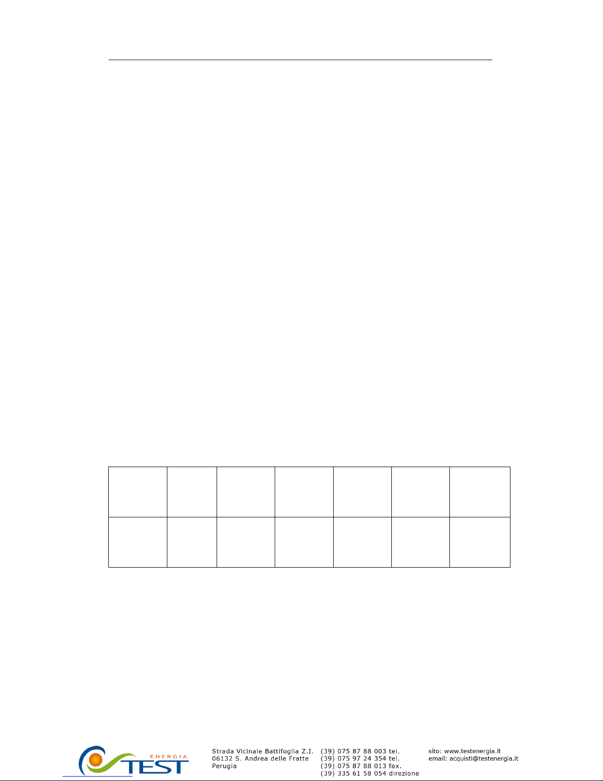
6、ModuleTiltAngle
Tiltangleistheanglebetweenmodulesandhorizon.Inordertogetthebesttilt
angle,asarule,weshouldsacrificesuperfluouspowerinsummerandmakeup
theshortageofthewinter.Accordingtothelocationofthesuninwinter,referto
tablefortherecommendedmoduletiltangleyoursite(seethebelowtable)
Site
latitudeIn
Degrees
0°-15°15°-25°25°-30°30°-35°35°-40°40°+
FixedTilt
Angle15°
Sameas
latitude
latitude+
5°
latitude+
10°
latitude+
15°
latitude+
20°
7、Blockingdiodes
BlockingdiodesaretypicallyplacedbetweenthebatteryandthePVmodule
outputtopreventbatterydischargeatnight.MostPVchargeregulatorsdohavea
nighttimedisconnectfeature.

Installation
Installation
Installation
InstallationManual
M anual
Manual
ManualFor
F or
For
ForThe
T he
The
TheSun
S un
Sun
SunEarth
E arth
Earth
EarthT
T
T
TP
P
P
PB-Series
B -Series
B-Series
B-Seriesof
o f
of
ofSolar
S olar
Solar
SolarPhotovoltaic
P hotovoltaic
Photovoltaic
PhotovoltaicModules
M odules
Modules
Modules
Page
Page
Page
Page7
7
7
7of
o f
of
of8
8
8
8
8、BypassDiodes
Partialshadingofanindividualina17.3voltor34.6volt“series”stringcancause
powerloss.Shadingmodulewillproducehot-pot.Thishotpotinteneratethe
encapsulatingpolymerandmakeitturntobrown.
Byhavingabypassdiode,theabovedcurrentwillbypasstheshadedmoduleina
seriescircuit,therebyminimizingmoduleheatingandarraycurrentlosses.
BypassDiodesElectricalCharacteristics
Type15SQ045UNITS
MaximumRepetitivePeakReverseVoltageVRRM45V
MaximumRMSVoltageVRMS31.5V
MaximumDCBlockingVoltageVDC45V
MaximumAverageForwardRectifiedCurrentIF(AV)15A
PeakForwardSurgeCurrent8.3mssinglehalf
sine-waveSuperimposedonratedload(JEDEC
method)
IFSM300A
PeakForwardVoltage@15ADC(Note1)VF0.5V
MaximumDCReverseCurrent@
TA
=25℃
atRatedDCBlockingVoltage@
T
A=100℃
IR0.5
50
mA
mA
TypicalThermalResistance(Note2)RθJA2.2℃/W
Junctiontemperaturerangeatreducedreverse
voltageVR≤80%VRRM
VR≤50%VRRM
InDCforwardmode
TJ
-50to+150
≤175
≤200
℃
StorageTemperatureRangeTSTG-50to+150℃
NOTES:1.300usPulseWidth.2%DudyCyote.
2.ThermalResistanceJunctiontoCase.
9、Maintenance
SunEarthsolarmoduleiddesignedaccordingtotheruleoflonglifeandfree
maintenance.Undermostconditions,normalrainfallandwindissufficientto
keepthemoduleglassclean.
You
shouldcleantheclasswithasoftclothusing
milddetergentandwater.Whencleantheback,pleasedon’tbreaktheTPT .
10、Others
10.1Ratedelectricalcharacteristicsarewithin±10%percentofmeasuredvaluesat
Standard
Test
Conditionsof1000W/m2,25℃celltemperatureandAM1.5solar
spectralirradiance.

Installation
Installation
Installation
InstallationManual
Ma nual
Manual
ManualFor
Fo r
For
ForThe
Th e
The
TheSun
Su n
Sun
SunEarth
Ea rth
Earth
EarthT
T
T
TP
P
P
PB-Series
B- Series
B-Series
B-Seriesof
of
o f
ofSolar
So lar
Solar
SolarPhotovoltaic
Ph otovoltaic
Photovoltaic
PhotovoltaicModules
Mo dules
Modules
Modules
Page
Page
Page
Page8
8
8
8of
of
o f
of8
8
8
8
10.2Undercertainconditions,aphotovoltaicmoduleislikelytoproducemorecurrent
and/orvoltagethanreportedatstandardtestconditions.Accordingly,thevalueof
IscandVocmarkedonthismoduleshouldbemultipliedbyafactorof1.25when
determiningcomponentstandardvalueswhichareconnectedtothePVoutput.
RefertoSection690-8oftheNationalElectricCodeforanadditionalmultiplying
factorof1.25whichmaybeapplicable.
Ningbo
Ningbo
Ningbo
NingboSolar
Sol ar
Solar
SolarElectric
El ectric
Electric
ElectricPower
Pow er
Power
PowerCo.,
Co.,
C o.,
Co.,Ltd.
Lt d.
Ltd.
Ltd.
No.211XingguangRoad,Hi-TechIndustrial
DevelopmentZone,Ningbo,China
Tel:
+86-574-87121761,87915161
Fax:+86-574-87131333
http:www.nbsolar.com
E-mail:rd@nbsolar.com
CopyrightNingboSolar,2010
Table of contents
Popular Solar Panel manuals by other brands

Solarbayer
Solarbayer NANOSOL 135 Product information

Grape Solar
Grape Solar GS-S-150-SF Safety and installation manual

ENN Solar Energy
ENN Solar Energy EST-110 installation manual

Hanwha Solar
Hanwha Solar HSL60P6-PB-1-xxx Series installation guide

select solar
select solar 05002MD03 installation guide

Flashfish
Flashfish TSP18V100W user manual


