18
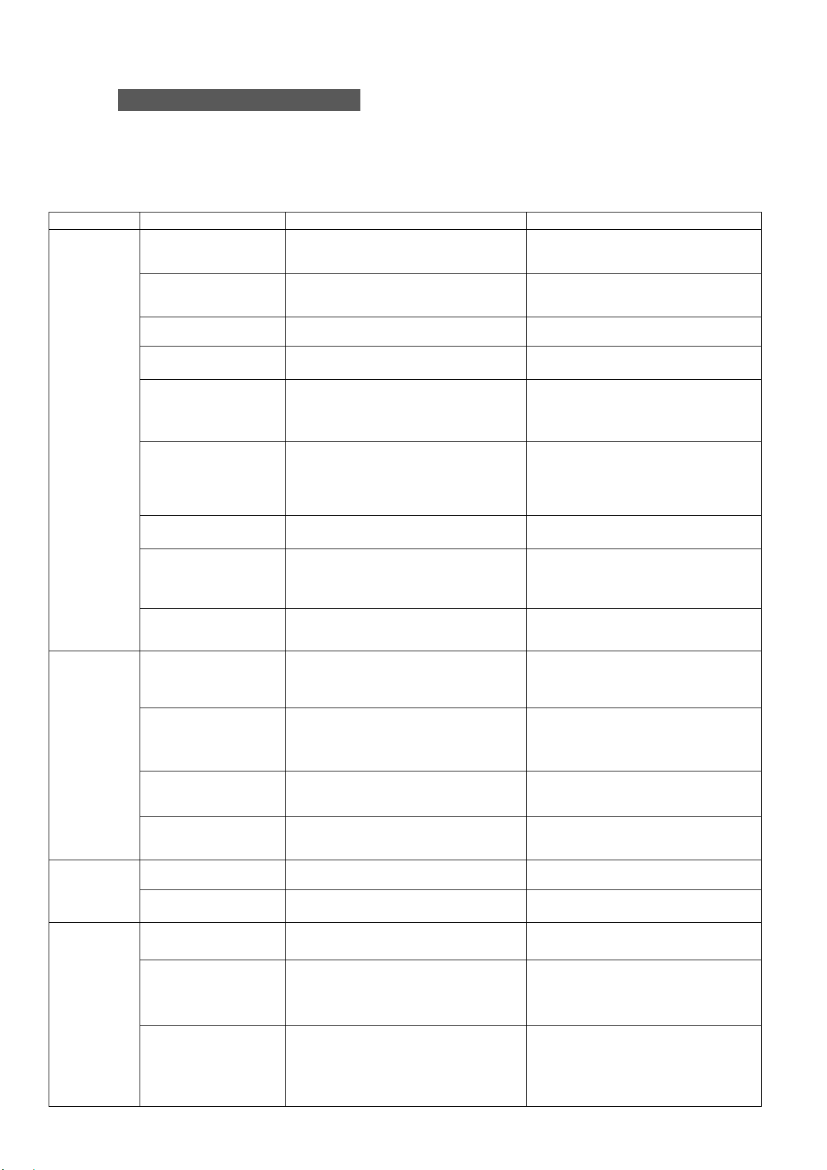
Troubleshooting Guide
If you experience no oil discharge, a high-pitched sound, or such other abnormal
phenomena soon after the installation, check the troubleshooting chart in the table
that follows.
If you cannot find out the cause of trouble, consult us or a dealer.
Table 4: Pump Troubleshooting Chart
No
discharge
from outlet
port.
Insufficient
flow or
pressure.
Abnormal
noise.
Motor failure.
Are wires at motor loose or
disconnected? Do operation test for
motor individually.
・Repair or replace pump.
Motor is wired
incorrectly or
disconnected.
Are wires at motor loose or
disconnected? Check direction of
rotation.
・Rewire motor in a correct rotation
indicated on label.
Coupling is damaged. Check connected area between pump
and motor.
・Replace coupling.
Liquid surface level
decreases.
Check liquid amount in tank.
・Refill tank with enough liquid.
・Control liquid level with level sensor.
Inlet port is clogged. Check the inlet port for clogging.
・Periodical cleaning on and
around inlet port.
・Insert a plate filter prior to the inlet
port as a pre-filtration.
Air drawn into pump
or pipes.
・On the first-run, after long term
storage or immediately after replacing
coolant
liquid, pump often doesn’t discharge
due to the trapped air.
・Perform air-bleeding on pump
or piping. Perform air-bleeding
in front of check valve if the one
is installed in outlet line.
Clogging or failure of
impellers. ・Check the impellers for clogging or
damage.
・Remove accumulated swarf.
・Repair or replace pump.
Aeration. ・Is pump sucking foam or air?
・Take measures to prevent suction
of air or tramp oil.
(ex. Change pump location, use
partition or defoamer )
Pipes connected to
outlet port is too
large.
Is outlet discharge flow rate sufficient?
・Use smaller pipes.
No
discharge
from
contaminant
drain port
Contaminant drain
port piping is too long
or
too high.
Pull off a pipe from the contaminant
drain port and check if liquid is being
delivered properly or not.
Piping must be no higher than
1 m from the tank bottom vertically,
and no longer than 3 m horizontally
.
Clogging of
contaminant drain
port.
Check inside the pipe for clogging. ・Clean inside the pipe periodically.
・Minimize the number of bends in
your pipe layout.
・Use larger pipe.
Clogging inside the
cyclone Check inside the cyclone for clogging. ・Remove swarf.
・Repair or replace pump.
Clogging or failure of
impellers. Check the impellers for clogging or
damage.
・Remove swarf.
・Repair or replace pump.
Liquid
leaks. Oil seal deterioration
or damage. Does liquid leak from drain
port (Rc 1/4)? Repair seal.
Repair or replace pump.
gasket deterioration
or damage. Does liquid leak from connected area? Repair or replace pump.
Breaker or
thermal
trips out.
・Motor failure.
・Wiring errors. ・Check motor wiring.
・Does motor start? ・Rewire motor.
・Repair or replace motor.
Overloading. Are motor output rating and coolant
viscosity adequate? ・Use motor with higher output rating.
・Use pump with lower capacity.
・Lower the pressure setting.
・Change the coolant types.
Coolant type is
incompatible.
(Viscosity is too high,
lubricity insufficient,
Pump failure)
・Is motor rotating?
・Are liquid viscosity and lubricity
adequate?
・Is there abnormal noise?
・Repair or replace pump.
・Change the types of coolant you use.