1
E
EE
E-
--
-
Series E
Series ESeries E
Series ES
SS
S
User’s Instruction Manual
User’s Instruction Manual User’s Instruction Manual
User’s Instruction Manual
<
<<
<Contents
ContentsContents
Contents>
>>
>
For Safe Operation
For Safe OperationFor Safe Operation
For Safe Operation
................................
................................................................
................................................................
................................................................
................................................................
................................................................
.................................................
..................................
.................
2
22
2
Safety Precautions
Safety PrecautionsSafety Precautions
Safety Precautions
................................
................................................................
................................................................
................................................................
................................................................
................................................................
..................................................
....................................
..................
5
55
5
●Safety Equipment .................................................................................................................. 5
●Safety Measures .................................................................................................................... 5
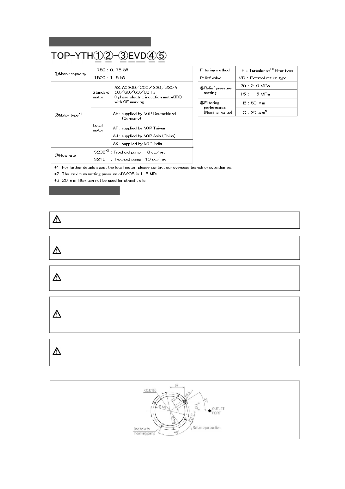
Model Numbering Sy
Model Numbering SyModel Numbering Sy
Model Numbering System
stemstem
stem
................................
................................................................
................................................................
................................................................
................................................................
................................................................
.......................................
..............
.......
6
66
6
Pump Installation
Pump InstallationPump Installation
Pump Installation
................................
................................................................
................................................................
................................................................
................................................................
................................................................
....................................................
........................................
....................
6
66
6
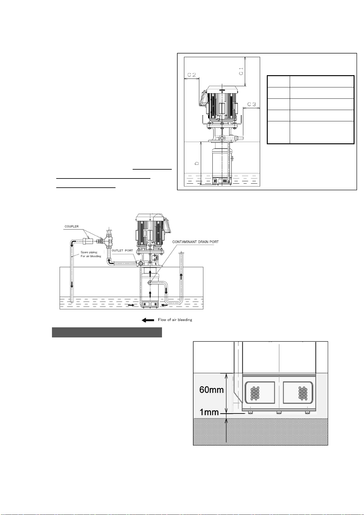
●Installation Site ...................................................................................................................... 6
●Required Space for Installation ............................................................................................. 8
●Recommended Installation Circuit. ........................................................................................ 8
Position of Pump Inlet Port
Position of Pump Inlet PortPosition of Pump Inlet Port
Position of Pump Inlet Port
................................
................................................................
................................................................
................................................................
................................................................
................................................................
......................................
............
......
8
88
8
Filters
FiltersFilters
Filters
................................
................................................................
................................................................
................................................................
................................................................
................................................................
................................................................
................................................................
......................................
............
......
9
99
9
●Performance of Turbulence Filter .......................................................................................... 9
Contaminant Drain Line
Contaminant Drain LineContaminant Drain Line
Contaminant Drain Line
................................
................................................................
................................................................
................................................................
................................................................
................................................................
........................................
................
........
10
1010
10
Outlet Port
Outlet PortOutlet Port
Outlet Port
................................
................................................................
................................................................
................................................................
................................................................
................................................................
............................................................
........................................................
............................
11
1111
11
Piping for the Pump
Piping for the PumpPiping for the Pump
Piping for the Pump
................................
................................................................
................................................................
................................................................
................................................................
................................................................
..............................................
............................
..............
12
1212
12
●Torque Applied on Pipe Connection .................................................................................... 12
●Connecting the Pipes .......................................................................................................... 12
●Pipes and Pipe Joints .......................................................................................................... 12
Electric Wiring
Electric WiringElectric Wiring
Electric Wiring
................................
................................................................
................................................................
................................................................
................................................................
................................................................
.......................................................
..............................................
.......................
13
1313
13
For Operation
For OperationFor Operation
For Operation
................................
................................................................
................................................................
................................................................
................................................................
................................................................
........................................................
................................................
........................
13
1313
13
●Start-up Checklist ................................................................................................................ 13
●Test Run .............................................................................................................................. 13
Inspections
InspectionsInspections
Inspections
................................
................................................................
................................................................
................................................................
................................................................
................................................................
...........................................................
......................................................
...........................
14
1414
14
●Daily Startup Inspections ..................................................................................................... 14
●Periodical Inspections .......................................................................................................... 14
Storage
StorageStorage
Storage
................................
................................................................
................................................................
................................................................
................................................................
................................................................
................................................................
................................................................
.................................
..
.
14
1414
14
Warranty
WarrantyWarranty
Warranty
................................
................................................................
................................................................
................................................................
................................................................
................................................................
...............................................................
..............................................................
...............................
15
1515
15
For Selecting a Pump
For Selecting a PumpFor Selecting a Pump
For Selecting a Pump
................................
................................................................
................................................................
................................................................
................................................................
................................................................
...........................................
......................
...........
15
1515
15
●Operating Method ................................................................................................................ 15
●Required Flow Rate ............................................................................................................. 15
●Required Pressure ............................................................................................................... 15
●Relief Valve Pressure Setting. ............................................................................................. 15
●Selecting Coolant Type and Viscosity Range. .................................................................... 15
●Operating Ambient Temperatures ....................................................................................... 16
●Fluid Temperature Range .................................................................................................... 16
●Compatible Work Materials. ................................................................................................ 16
Motor Selection
Motor SelectionMotor Selection
Motor Selection
................................
................................................................
................................................................
................................................................
................................................................
................................................................
.....................................................
..........................................
.....................
17
1717
17
●Required Power for the Pump. ............................................................................................ 17
● Voltage and Frequency ...................................................................................................... 17
Suction Performance
Suction PerformanceSuction Performance
Suction Performance
................................
................................................................
................................................................
................................................................
................................................................
................................................................
............................................
........................
............
18
1818
18
Internal Structure
Internal StructureInternal Structure
Internal Structure
................................
................................................................
................................................................
................................................................
................................................................
................................................................
..................................................
....................................
..................
18
1818
18
Troubleshooting Guide
Troubleshooting GuideTroubleshooting Guide
Troubleshooting Guide
................................
................................................................
................................................................
................................................................
................................................................
................................................................
..........................................
....................
..........
19
1919
19
Backwashing
BackwashingBackwashing
Backwashing................................
................................................................
................................................................
................................................................
................................................................
................................................................
.........................................................
..................................................
.........................
20
2020
20