NIPPON POP RIVETS AND FASTENERS PNT800 Series User manual

POP NUT TOOL
PNT800
INSTRUCTION MANUAL
The PNT800 is solely for use with POP Nuts.
Read this manual thoroughly before you start and use the PNT800 according
to the instructions.
Store this manual where the person who uses the tool may refer to it easily.
NIPPON POP RIVETS AND FASTENERS LTD.

PNT800
CONTENTS
SafetyPrecautions
・・・・1
1.Part names
・・・・4
2.Outline
・・・・5
3.Specifications
・・・・6
4.Preparations for use
・・・・7
5.Precautions on use
・・・・10
6.How to use the PNT800
・・・・11
7.Maintenance and testing
・・・・14
8.Troubleshooting
・・・・21
9.Parts List
・・・・23
10.Cross-sectional diagram of the PNT800 ・・・・25

PNT800
Safety Precautions
-Read all the safety precautions carefully before you use this tool and
observe them carefully in practice.
-The safety precautions are classified as follows:
WARNING!
Incorrect operation caused by failure to observe this type of precaution
could cause death or serious injury.
Caution!
Incorrect operation caused by failure to observe this type of precaution
could cause injury or physical damage.
-After reading this manual, keep it in a place where the actual user can
refer to it easily.
-Only use this tool for fastening appropriate Pop Nuts.
(Refer to the Pop Nut catalog to select appropriate Pop Nuts).
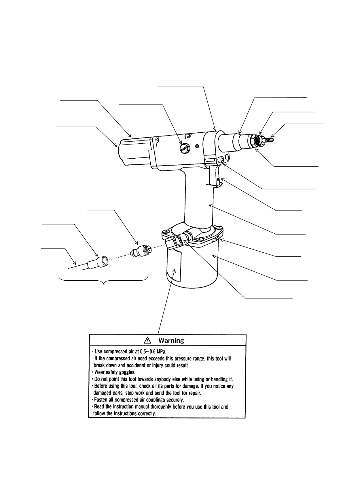
WARNING!
1. Use compressed air at a pressure of 0.5~0.6 MPa.
Use of compressed air at higher pressure could break the tool as well as
causing accident or injury.
2. Do not point this tool towards anybody else when you use it.
Accident or injury could result as bystanders are entangled or squashed by
the mandrel.
3. Wear safety goggles (satisfying JIS T8147).
If this tool breaks down, parts or pressurized oil could fly out, causing
accident or injury.
4. Before using this tool, check all its parts for damage. If you notice any
damaged parts, stop work and send the tool for repair.
Accident or injury could result if you use this tool while it is damaged.
5. Make sure the compressed air supply couplings are secure.
If the screw threads of the couplings do not match perfectly, or if they are
not screwed in far enough, the hoses and couplers etc. could come off while
the tool is in use, possibly causing accident or injury.
*Refer to section one (p.4) for details of part names.
*A warning label is stuck to the chamber of this tool. If the label is badly
damaged or if it peels off, contact your supplier or one of our offices to
obtain a replacement (a replacement fee will be charged).
1

PNT800
Caution!
1. Before servicing this tool, replacing any of its parts, or otherwise
assembling or disassembling it, disconnect all compressed air couplings to
make sure it is not supplied with compressed air.
If you start to work on this tool while it is supplied with compressed air,
parts or oil could fly out or the tool could start moving unexpectedly,
causing accident or injury.
2. The fill screws must be fully tightened before you use this tool.
If any of the fill screws are loose or missing, oil can spurt out, causing
accident or injury.
3. Do not use this tool without its nose housing.
Your fingers could be trapped and injured by the exposed parts.
4. Only use parts that are provided or recommended by Nippon Pop Rivets
and Fasteners. Attach the appropriate parts to this tool for the Pop Nuts
you are using.
Other than reducing performance, using the wrong attachments could
cause malfunctions leading to accident or injury.
5. Do not alter the tool without permission from the manufacturer.
Resulting malfunctions could lead to accident or injury.
6. This tool should be serviced by a qualified technician who has a full
understanding of its functions and mechanisms. Even experienced
technicians should refer to this instruction manual and proceed carefully
as instructed.
If this tool is serviced by someone who lacks the required level of
knowledge and ability, performance could be reduced and malfunctions
could result, leading to accident or injury.
7. Order repairs to this tool from the manufacturer.
If the tool needs repairing, contact your supplier or the manufacturer.
If this tool is repaired by someone who lacks the required level of
knowledge and ability, performance could be reduced and malfunctions
could result, leading to accident or injury.
8. Keep the grip of the handle dry and clean at all times. It must be free of
oil and grease.
If the grip is slippery, the user could drop the tool.
9. Do not grip or turn the mandrel with your fingers etc. while the tool is
connected to its compressed air supply.
The mandrel could start moving and injure your fingers.
2

PNT800
3
10. Never use organic solvents on the handle, rear case, front case and trigger
(these parts are all made of polycarbonate).
Breakage of these parts above could cause parts to fly off, causing accident or
injury.
11. Wear protective gloves while using this tool.
Your fingers or hands could get trapped or squashed in the mandrel, causing
accident or injury.
12. Beware of air venting from the air vent.
Cloudy air occasionally blows strongly out of the air vent, so keep your face
(particularly your eyes) away from the air vent. The exhaust air may also dirty
nearby objects, so care is required.
(This problem mainly occurs when the compressed air supplied contains oil or
moisture.)
*Refer to section one (p.4) for details of part names.
PNT800
1. Part names
Front case
4
Lock nut
Control knob
Thread size
(Rc 1/4)
Exhaust holes
Fill screw
Rear case
Mandrel
Nose piece
Trigger
Handle
Chamber
Coupler
(Plug)
Not attached
Exhaust hole
Hose
Coupler
(Socket)
Nose housing
Warning label

PNT800
2. Outline
The PNT800 is a small, light tool for fastening Pop Nuts. It is driven by
compressed air.
Table 2-1 lists the Pop Nuts that can be fastened using this tool. The nosepiece
and mandrel must be changed to fit some sizes of Pop Nut. (See table 2-2)
Table 2-1 Pop Nuts that can be fastened using this tool Size
Pop nut type Material M3 M4 M5 M6 M8 M10
Steel ○○○○○○
Alminum ○○○○○○
Standard nut Stainless ○○○○○
Steel ○○○○○○
Alminum ○○○○○○
Sealed nut Stainless ○○○○○
Steel ○○○○○
Hexgonal nut Alminum ○○○○
Tetra nut Steel ○○○○
Rollet nut Steel ○○○○
Table 2-2 Nose piece Mandrel
Pop nut size
Nut tool
No.
No. I.D. No. Thread size
I.D.M8×1.0
Thread size
M3×0.5 − PNT600-02-3 φ4.0 PNT600-02-3 M3×0.5
M4×0.7 PNT800-4 PNT600-02-4 φ4.5 PNT600-02-4 M4×0.7
M5×0.8 PNT800-5 PNT600-02-5 φ5.1 PNT600-02-5 M5×0.8
M6×1.0 PNT800-6 PNT600-02-6 φ6.1 PNT600-02-6 M6×1.0
M8×1.25 − PNT600-02-8 φ8.1 PNT600-02-8 M8×1.25
M10×1.5 − PNT600-02-10 φ10.1 PNT600-02-10 M10×1.5
M4,M5,M6set PNT800
*Refer to section one (p.4) for details of part names.
*Refer to page 15 for details of nosepiece and mandrel replacement.
5
PNT800
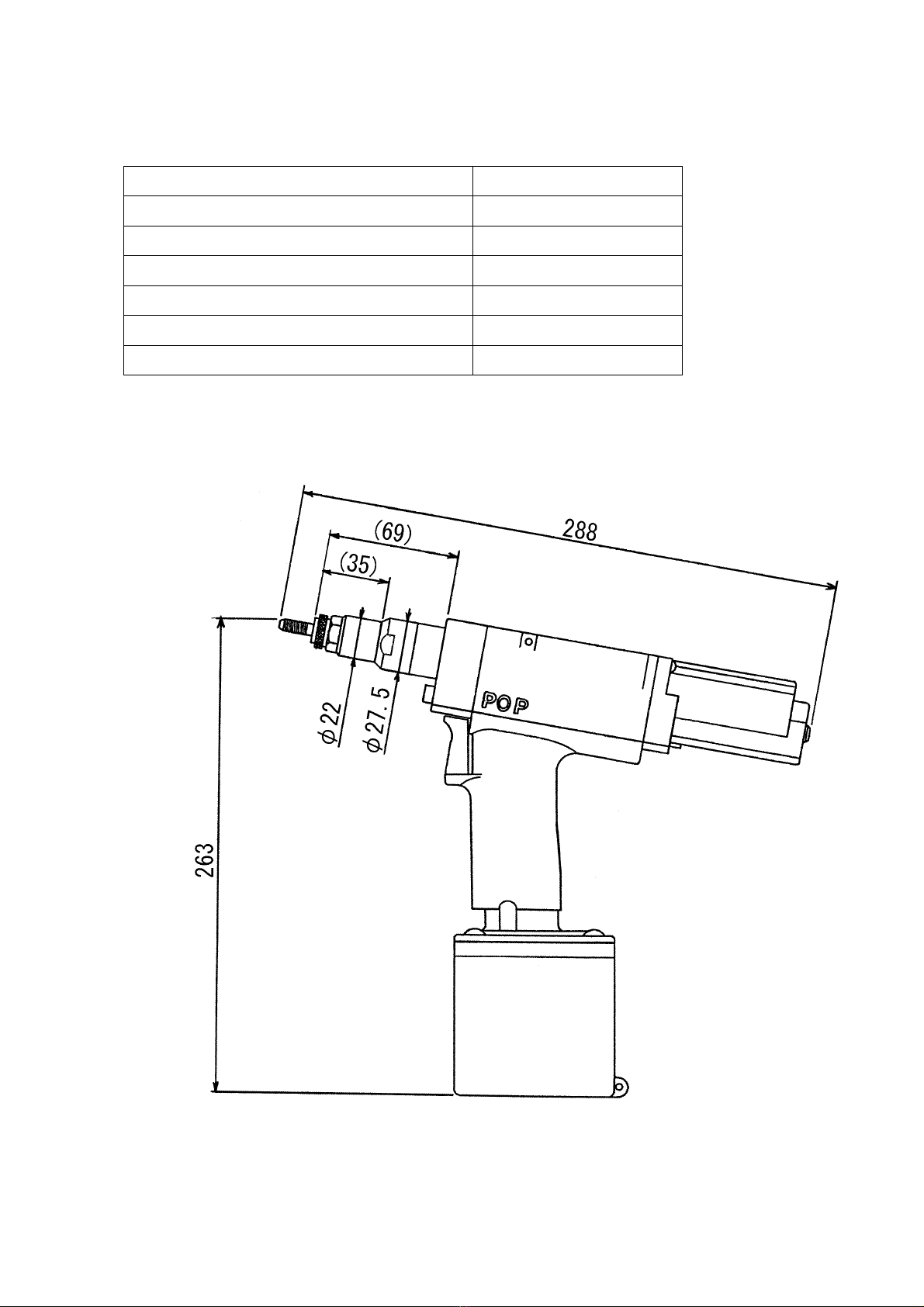
3. Specifications
Table 3-1 Specifications
Model PNT800
Weight 1.68kg
Overall length 288mm
Overall height 263mm
Stroke 1.3~6.5mm
Compressed air pressure required 0.5~0.6MPa
Pop-Nut that may be fastened See table 2-1 (p.5)
Figure 3-1
6

PNT800
4. Preparations for use
1. Check that the right nosepiece and mandrel are fitted for the Pop Nut.
Adjust the protruding length of the mandrel.
(Refer to page 15 for details of replacement and adjustment).
2. The coupling diameter of the compressed air supply coupling is Rc 1/4.
Connect a joint or coupler of connection diameter R1/4 to supply compressed air.
(The coupler and joint are not provided.)
3. An air filter, regulator and lubricator should be fitted in the air line between the
compressor and the tool, within 3m of the tool. Adjust the supply pressure and
the drip volume of the lubricator oil.
-Compressed air pressure: 0.5~0.6 MPa.
-Oil drip volume from the lubricator: 1~2 drops/ 20 nuts fastened
7
Coupler (Plug)
Thread size R 1/4
Regulator
I.D.6.5mm Min.
Hose
Compressor
A
ir filter
3m Max.
Coupler(Socket)
Lubricator
Figure 4-1
Not attached
WARNING!
According to the actual operating temperature, use an air hose able to withstand
0.7MPa at the maximum ordinary operating pressure. Also make sure the hose
material is suitable for the operating environment (e.g. oil proof, wear and abrasion
resistance etc.).
*For details, refer to a hose manufacturer's catalog.

PNT800
4. Stroke Adjustment
Adjust the stroke length according to POP Nut size and the thickness of
workpiece.
Note: The stroke increases and decreases by change of air pressure (about 0.1mm
per 0.1MPa) and makes the air pressure constant as much as possible.
《Procedure》
(1) Investigation of Stroke
Find maximum stroke S max. , minimum stroke Smin., and stroke E for the POP Nut
and workpiece thickness from "Proper stroke of POP Nut" (p.9).
[Example]
(Figure4-2)
POP Nut: SPH625
Maximum stroke
(
SMax.
)
Workpiece thickness: 1.5mm
S max. = 3.4 from formula or graph
S min. = 3.0 (S
max.−0.4.) from formula
E= 3.6 (S
max. + 0.2) from formula
Proper stroke: 3.0−3.4 (S min.−Smax.)
(2) Adjustment of Stroke Workpiece thickness
Adjust the stroke E and adjust proper
stroke (S min.−Smax.).
Lock screw
(Use 1.5mm hexa. wrench)
Lock screw
(Never loosen)
Edge of control nut
Scale
Control nut
Control knob
①Loosen the M3 lock screw on the control
nut using a 1.5mm hexagonal wrench.
Adjust stroke by turning control knob
clockwise to decrease and anti-clockwise
to increase stroke. Stroke E is indicated
by the edge of control nut. Tighten the
lock screw. (Figure.4-3)
Note: Never loosen the lock screw on the
control knob, as this will disturb the stroke. (Figure4-3)
②Set a POP Nut and measure the stroke
with calipers etc. and confirm the
difference with E. Readjust the stroke
according to ①so that the stroke is E±
0.1mm. (Figure.4-4)
8
Note: Using the control knob, adjustments
equal to 0.2mm per quarter turn can be made.
③Set a POP Nut using work piece or the test
piece, and check the stroke whether it is proper stroke (S min.−Smax.). Readjust
when the stroke has come off from S min. or Smax.. (Figure 4-5)
(Figure4-4)
(Figure4-5)
Stroke E
Stroke S min.−Smax.

PNT800
(3)Proper stroke for POP Nut
・Confirm stroke ( S max., S min., E) corresponding to the POP Nut and the
workpiece thickness used.
Formula of stroke
・
A
djust the stroke E and adjust
proper stroke (S min.−Smax.).
Thread size Maximum
stroke: S max Minimum
stroke: S min Stroke without
workpiece:E
M3×0.5 1.2+(N-t) SMax-0.2 SMax+0.1
M4×0.7 1.6+(N-t) SMax-0.3 SMax+0.1
M5×0.8 2.0+(N-t) SMax-0.3 SMax+0.1
M6×1.0 2.4+(N-t) SMax-0.4 SMax+0.2
M8 ×
1.25RLT 2.4+(N-t) SMax-0.4 SMax+0.2
M8×1.25 2.8+(N-t) SMax-0.4 SMax+0.2
M10×1.5 3.0+(N-t) SMax-0.4 SMax+0.2
t:workpiece thickness
N: 1/10 of the last
two digit of the part
number
(Example)
625:25/10=2.5
*
*M8×1.25RLT shows M8 steel RLT types.
M4, M5 and M6 steel RLT types are the same stroke as standard types.
Smax.-t (Maximum stroke −Workpiece thickness) graph
9
Maximum stroke(SMax. )
Workpiece thickness
Use the formula o
f
stroke for POP Nuts
that are not indicated in
S max.-t graph.
POP Nut No.(Example)
625 Maximum
thickness: 2.5mm
Thread size: M6×1.0

PNT800
10
5. Precautions on use
The following precautions must be observed to ensure that the performance and
service life of this tool are maintained.
1. Use the correct compressed air pressure
Use compressed air at a pressure in the range 0.5~0.6 MPa.
If the compressed air pressure used exceeds the range above, this tool will break
down and accident or injury could result. If the pressure is below the range, the
tool may be unable to fasten Pop Nuts fully.
Use a regulator to ensure compressed air supply in the correct pressure range.
(See p.7)
2. Use an air filter
If the compressed air supplied contains dirt or moisture, it will have an adverse
effect on the tool, so use an air filter in the air supply. (See p.7)
3. Use a lubricator
If the tool goes without an adequate supply of lubricant, its service life will be
shortened.
Install a lubricator within 3m of the tool and adjust its drip rate.
(Recommended drip volume = 1~2 drops for 20 fastenings).
*Refer to the instruction manual for the lubricator used for details of the
adjustment method and the correct lubricant oil to use.
4. Parts to use (Nose piece, mandrel)
Replace these pieces with the appropriate versions for the Pop Nuts (see table
2-2).
5. Hydraulic oil
Use the designated hydraulic oil.
Use one of the hydraulic oil brands specified in table 5-1. Use of any other oil
could cause a breakdown.
Table 5-1 Specified hydraulic oils
Company name Product name
Idemitsu Daphne Hydro 68A
Mobile Mobile DTE26
Cosmo Cosmo Olpas 68
Esso Telesso 68
Nisseki FBK RO68
Mitsubishi Diamond Lube RO68 (N)
Showa Shell Shell Telus Oil C68

PNT800
6. How to use the PNT800
Before setting Pop Nuts with this tool, refer to the section "4. Preparations for
use" on pages seven and eight.
《Procedure》
1. Mounting
When the Pop Nut is gripped gently and pressed by the mandrel with a force of
approximately 49N or more, the mandrel turns clockwise.
Screw the Pop Nut down onto the mandrel.
Once the flange of the Pop Nut comes into contact with the nose piece, the
clockwise rotation of the mandrel stops automatically.
Mandrel
Figure 6-1
Precautions on mounting
Keep pushing until the clockwise rotation of the mandrel stops automatically.
If the Pop Nut is not fully mounted, the caulk stroke will be inconsistent.
OK
NG
Figure 6-2
11
PNT800
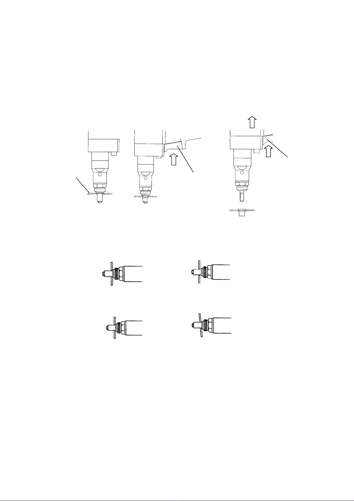
2. Fastening and detachment
Push the Pop Nut perpendicularly into the hole in the base material and pull the
trigger (Figure 6-3).
Keep pulling the trigger throughout fastening and detachment.
Otherwise, detachment cannot be completed.
The Pop Nut is fastened and the tool automatically switches to counterclockwise
rotation to detach from the Pop Nut (Figure 6-4). Pull lightly
Trigger
Pull
Figure 6-4
Trigger
Keep pulling
Base material
Figure 6-3
Precautions on fastening
(1) Fit the flange of the Pop Nut closely against the base material.
OK NG
Figure 6-5
(2) Do not tilt the tool. NG
OK
Figure 6-6
(3) Double caulking (fastening a Pop Nut again after it has initially been
fastened once). If you try to refasten a Pop Nut that has already been fastened,
either the tool or the Pop Nut will break.
Precautions on tool detachment
Pull the tool throughout detachment.
Otherwise, the mandrel cannot detach without reverse rotation.
12

PNT800
3. Stopping the mandrel's counterclockwise rotation.
Release the trigger to stop the mandrel (Figure 6-7).
13
Figure 6-9
Figure 6-7
Release Trigger
Figure 6-8
Regular mandrel cleaning and lubricant
-Clean the mandrel after every 50〜60 fastenings. (See Figures 6-8 and 6-9)
After fastening tens of Pop Nuts, metal fragments can stick to the mandrel and
it can run short of lubrication, making it impossible to mount Pop Nuts
smoothly. If you continue to use the tool in this condition, it will become
impossible to mount Pop Nuts at all and the mandrel will wear more rapidly.
4. What to do when the Pop Nut is not detached correctly
(1) If the reverse rotation of the mandrel stops before the Pop Nut is detached from
the mandrel (if you released the trigger too early).
Pull the trigger while pressing the control knob. Mandrel starts reverse rotation
and detaches the Pop Nut (Figure 6-10). Rotate
Trigger
Control knob
Ca
p
screw
Nose housing
Lock pin holder
Pull
While pressing
Figure 6-12
Figure 6-10 Figure 6-11
PNT800
(2) If the Pop Nut jams and the strength of the air motor is insufficient to detach the
mandrel.
①Detach the coupler to stop the supply of compressed air.
②Line up the female screw of the lock pin holder with the hole in the side of the nose
housing and screw the cap screw provided (M4×20) into the lock pin holder
(Figure 6-11).
③Turn the body of the tool counterclockwise to detach it from the Pop Nut (Figure
6-12).
7. Maintenance and testing
Table 7-1
No. Item Purpose
1 Lubricant spray for rotating parts. -To prevent early loss of the mandrel
rotation force.
2 Replacement of mandrel and nose
piece and adjustment of mandrel
protrusion length.
-Replacement and adjustment to change
the Pop Nuts used.
-Replacement and adjustment in case of
breakage.
3 Control nut, T valve push rod
replacement. -Replacement and adjustment in case of
breakage.
4 Oil replacement -Resetting the caulk stroke.
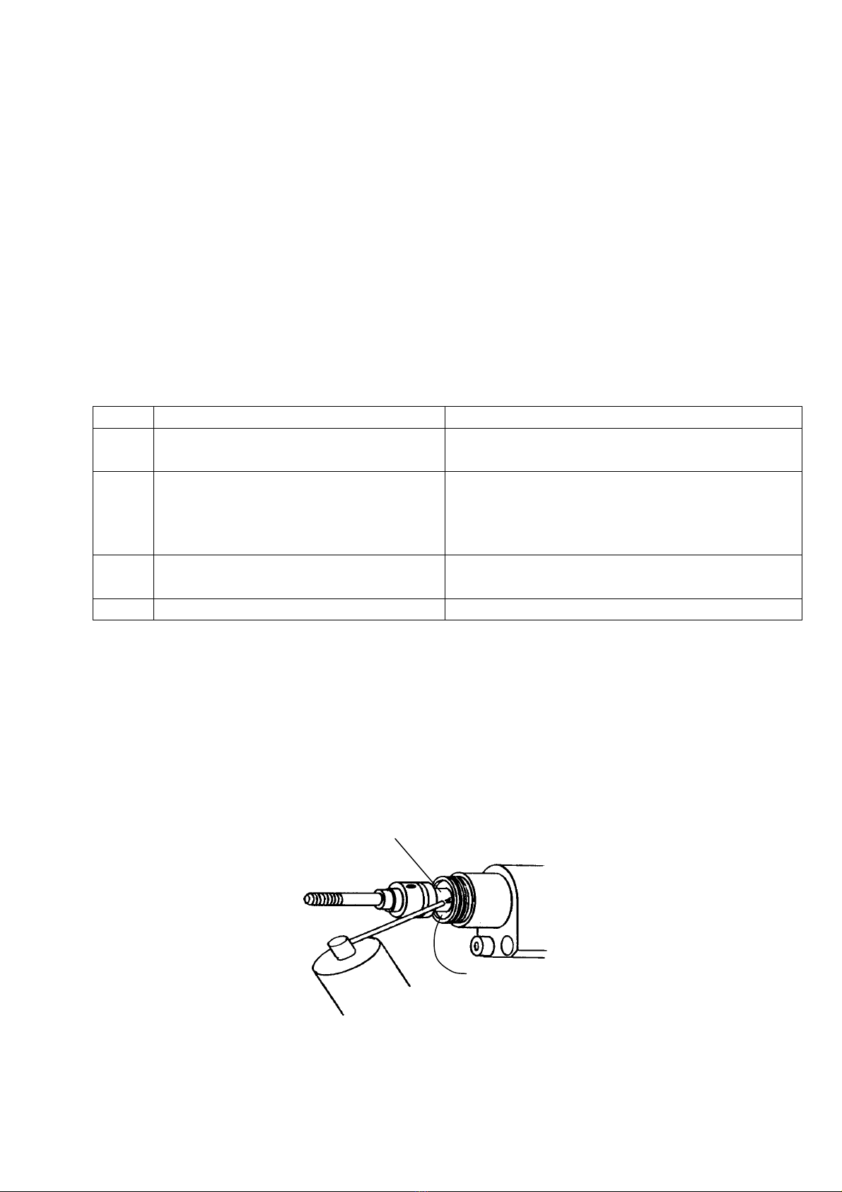
1. Lubricant spray for rotating parts.
After fastening around 1,000 Pop Nuts, wear between the spin-pull head and the
spin-pull head case will start to cause heating, drying and rattling. Rotation will be
slower, with less torque.
Follow the procedure from 2.(1) to remove the nose housing and spray lubricant
between the spin-pull head and the spin-pull head case.
Spin pull head
Spin pull head case
Lubricant spray
Figure 7-1
14
PNT800
2. Mandrel replacement, nosepiece replacement and mandrel protrusion length
adjustment
Use the designated parts to match the Pop Nut you will be using. (See p.5 table
2-2) Replace any parts that become worn or damaged.
(1) Mandrel replacement
《Procedure》
①Detach the coupler to stop the supply of compressed air.
②Use a 23mm spanner to unscrew and remove the nose housing.(See Figure 7-2)
③Push the lock pin holder in with your finger while you turn the mandrel to the left
to remove it for replacement.
S
p
in
p
ull head case
Mandrel
Figure 7-3
Push
Lock pin holder
Nose housing Figure 7-2
④Push the lock pin holder in with your finger while you screw the new mandrel into
the spin-pull head until it stops. Release the lock pin holder so that it returns to its
original position.
If the lock pin holder does not return to its original position, turn the mandrel
slightly to the left.
The lock pin holder will return to its original position. (See figure 7-3)
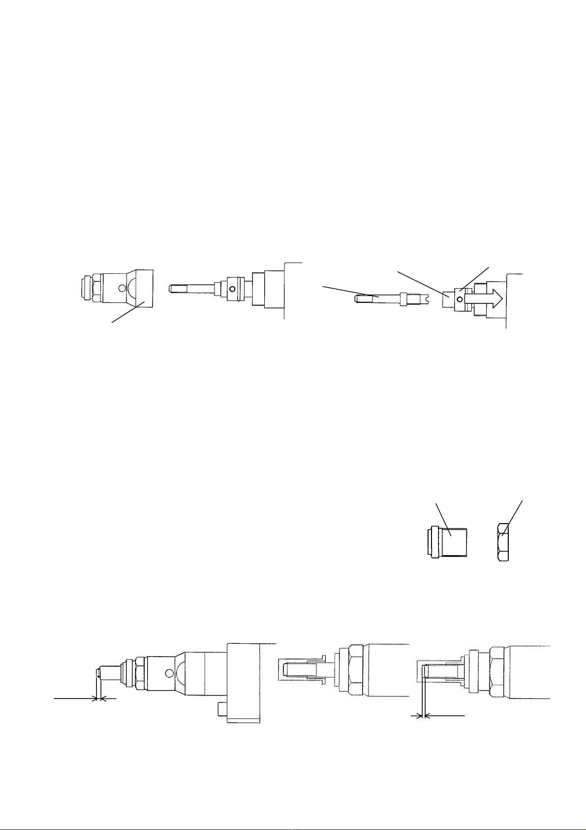
(2) Nose piece replacement, adjustment of the mandrel
protrusion length Procedure Nose piece Lock nut
①Detach the coupler to stop the supply of compressed
air.
②Use a 23mm and a 19mm spanner to loosen the lock
nut and remove the nose piece and the lock nut from
the nose housing. Change the nose piece (Figure 7-4).
Figure 7-4
One pitchOne thread
Figure 7-6
Figure 7-5
15

PNT800
③Screw the lock nut and nosepiece into the nose housing.
④Open end: Screw a Pop Nut onto the mandrel and adjust the nosepiece so that
approximately one thread of the mandrel screw thread extends beyond the Pop Nut
(Figure 7-5).
Closed end: Screw a POP Nut onto the mandrel until stopping, and adjust the
nosepiece at the position returned by one rotation (one screw pitch). (Figure 7-6)
⑤Screw the lock nut and the nose housing together to fasten the nosepiece in the
place.
3. Replacement of the control nut and the T valve push rod
If the mandrel breaks or the screw thread of a Pop Nut is broken by an excessive
stroke, the control nut and valve push rod may be broken.
《Procedure》
(1) Detach the coupler to stop the supply of compressed air.
(2) Use a cross-head screwdriver to remove the truss machine screws and detach the
front case (Figure 7-7).
(3) Use the 1.5mm hexagonal wrench (provided) to loosen the lock screw on the control
nut and turn the control knob to the left until the control nut reaches the end of its
travel (Figure 7-8).
Control nut
Truss screw
Front case
Lock screw
Figure 7-8
Figure 7-7
(4) Press the control knob and line up the projection on the control nut with the mast
housing, then turn the control knob to the left to remove it. Remove these parts as
an assembly from the body of the tool (Figures 7-9 and 7-10).
(5) Use the 1.5mm hexagonal wrench to loosen the lock screws of the control knob and
the control nut and remove them from the T valve push rod (Figure 7-11).
Projection
Tvalve push rod Lock screw
Press and turn
Mast housing
Control nut
Control knob
A
ssembly
Fi
g
ure 7-10
Figure 7-11
Figure 7-9
16

PNT800
(6) Adjust the total length of the assembly to 66±0.1mm, and tighten the
lock screw on the control knob hard. (Figure 7-12)
(Figure 7-12)
(7) Push the assembly into the body of the tool, and reverse the above
procedure to reassemble all parts.
(8) Loosen the lock screw on the control nut and turn the control knob to the
right until the control nut stops at the end of its movement, and then
tighten the lock screw. (Figure 7-13)
(9) Set a Pop Nut without workpiece, and check the stroke. If stroke of
1.3mm or less is obtained, it is normal. (Figure 7-14)
17
Figure 7-13
Lock screw
Stroke
Figure 7-14
Note: When stroke is over (1.3mm or more), check the assembly length
(proper length: 66±0.1), and readjust.
When other troubles are caused, do appropriate treatment refer to the "8.
Troubleshooting" (p.21).
PNT800
4. Oil replacement
If the stroke gets too short due to a lack of hydraulic oil (if a proper caulk
stroke is impossible, even after stroke adjustment), follow the procedure
below to replace the hydraulic oil.
If the stroke again becomes inadequate immediately after replacement of
oil, the oil seal must be replaced. Send the tool for repair.
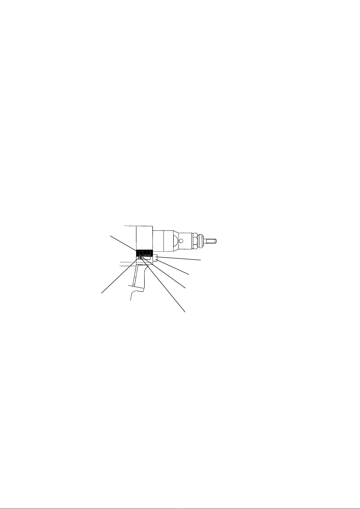
《Procedure》
(1) Detach the coupler to stop the supply of compressed air.
(2) Set the position of the control nut to approximately 10mm.
(Refer to "(2) Adjustment of stroke" on p.8.)
*The maximum stroke of the tool is 6.5mm.
*If control nut is not set to around 10mm, the valve and control nut could
break.
Note: Don't loosen the lock screw of the control knob as this would disturb
the stroke (Figure 7-14).
Lock screw (1.5mm hexa. wrench)
Control nut
(Set the position to 10mm)
Graduation
End of the control nut
Lock screw (Never loosen)
Control knob
Figure 7-14
(3) Use a cross-head screwdriver to remove the truss machine screws
(Figure 7-15).
(4) Stand the tool with the chamber uppermost and lift the chamber off. Pull
the air piston assembly and the tube out (Figure 7-16).
18
This manual suits for next models
3
Table of contents
Other NIPPON POP RIVETS AND FASTENERS Power Tools manuals


