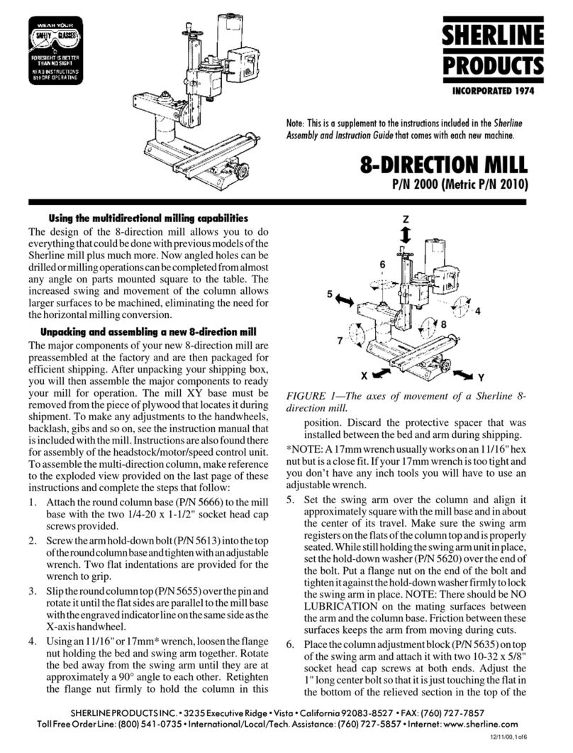
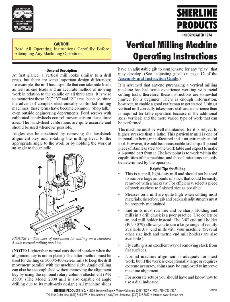
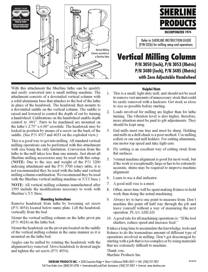
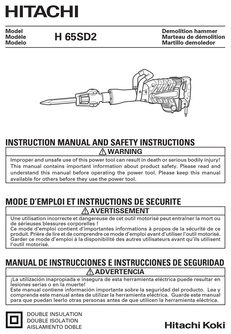
Sherline Products 2000 User manual

Why these upgrades came about
WiththeintroductionofanewproductliketheModel2000
mill,itisimpossibletoanticipatealltheusesandsetupsour
customers will attempt with it. After several months of
feedback, we noticed several areas where customers had
suggested a need for greater clearance or capacity. Some
users noted that lowering the column all the way down
withoutthecolumnspacerblockinplacewouldsometimes
causethebottomoftherotaryattachmenttohitthemillvise.
Also, when using small end mills, the column could not be
loweredenoughtogetthecutterlowerthanthetablesurface
formillingthesideofapartevenwiththecolumnextension
removed.Theenclosedupgradeeliminatestheseproblems
by allowing the column saddle to be lowered an additional
1.6".
Thecolumnsaddlelockupgradeprovidesasuperiormethod
of preventing saddle movement by locking the saddle nut
against the leadscrew. This is much more positive than the
existing friction saddle lock. We have looked for a way to
produce this for years, but it required finding a way to start
a thread in exactly the same place each time so that the
lockingmovementcouldbeconfinedtoalimitedquadrant.
A new piece of equipment in our factory now makes it
possibletocontrolthisaccurately,sothelockwillbeadded
to all production mills from now on. Upgrade kits will be
available for all older Sherline mills. For purchasers of the
“top-of-the-line”Model2000,wehaveincludedthelocking
lever upgrade at no charge.
If you have been using your mill and have not encountered
anyproblemsalongtheselines,itisnotnecessarytoinstall
theupgradesatthistime.Ifyoudorunintoaproblemwhere
youneedtolower the saddlemorethanitwill currently go,
you can always install it at that time. However, you will
probably find the new column locking lever to be far
superiortotheoldfrictionlock,andaslongasyouraregoing
Model 2000 Mill Upgrade
Installation Instructions
Column travel modification
P/N 4017U Saddle locking lever upgrade
2/26/99
SHERLINE PRODUCTS INC. 2350 Oak Ridge Way Vista California 92083 FAX: (760) 727-7857
Toll Free Order Line: (800) 541-0735 International/Local/Tech. Assistance: (760) 727-5857 Internet: www.sherline.com
SHERLINE
PRODUCTS
INCORPORATED 1974
SADDLETRAVEL
EXTENSION
SADDLE LOCKING LEVER
(Turn in direction of
arrow to release)
tothetroubletoreplaceit,youmightaswellinstallthewhole
upgrade at the same time.
Ifyoudonotwishtoinstalltheseupgradesyourself,wewill
begladto doitforyou fora$15.00handling fee.Youmust
pay the cost of shipping the unit to us, and we will pay for
returnshipping.Justreturnyourcolumnandsaddleunit(not
thewholemill)alongwiththeupgradepackagecomponents.
Wewillinstallthekitandreturnthecolumn/saddletoyou.
Wefeelthatmostof our customers will prefertodothejob
themselvesasformostpeopleitiseasierthanpackagingthe
columnforshipping.
Disadvantages to lowering the saddle and how to
overcome them
Lowering the saddle makes it easier to work close to the
table.Thetrade-offthatalwaysoccurswithanyengineering
compromise is that movement at the top of the travel is
limited by the same amount as is gained at the bottom.
Certain tall setups that involve multiple accessories can
stack up to a height that may require more clearance at the
top end. You will probably find that with the upgrade in
placeyouwilloperatethemillwiththecolumnspacerblock
in place most of the time. To achieve more height than that
spacercanprovideyouhaveachoiceofeitherpurchasinga
secondcolumnspacerblockorremovingthesaddleextension
for jobs that require the additional height.
Installing the saddle travel and locking lever upgrades
1.Removetheheadstock/motor/speedcontrolunitfromthe
saddlepin.
2. Remove the four socket head cap screws that hold the
column bed to the rotary attachment.
3. Remove the four socket head cap screws that hold the
moveableclampdisktothearmmount.Indexthemoveable
clampdisk180°sothecolumnbedholepatterniscloserto
the bottom and reinstall the four socket head cap screws.

4. Remove the Z-axis column saddle lock from the saddle.
5. Remove the leadscrew from the column bed. Do this by
first removing the socket head cap screw that holds the
saddletothesaddlenut.Thenremovethecountersunkscrew
atthetopofthecolumnthatholdstheleadscrewthrusttothe
column. The leadscrew, thrust and handwheel can now be
removed as a unit.
FIGURE1—Filethetopendofthemountingsurfaceofthe
bedflat.Youwillbeextendingthemachinedflatsurfacean
additional 1/4" or so for a total of 3-3/4" of flat.
6. On the bottom of the bed, a flat has been machined with
enough clearance for the existing rotary attachment. This
flatwillneedtobeextendedapproximately1/4"withtheuse
ofafile.(SeeFig.1.)Thiswillallowtheloweredcolumnto
be bolted flat against the moveable clamp disk. Use a flat
mill file and remove at least the same depth of material as
wasmachinedawayonyourcolumn.Don’tfileanymoreof
the existing machined surface than is necessary. It is OK if
you go a little deeper at the top end as there is plenty of
machinedflatspacetoalignthecolumn.Ifyoudon’tgodeep
enough, the column will not sit flat against the clamp disk.
7. The leadscrew must be shortened so that it will clear the
topoftherotarycolumnattachment.Removetheoldsaddle
nut.Threadthenewlockingleverontotheleadscrew.Then
threadthenewsaddlenutupagainstthelockinglever.The
sidewiththespringloadedballshouldfacethelockinglever.
Bydoingthisnow,youdonothavetoworryaboutstarting
it over the freshly cut thread ends.
FIGURE2—Theleadscrewisshortenedsothatthethread
length is 6.45". By threading on the locking lever and new
saddle nut before making your cut, you will not have to
worryaboutgetting themstartedover acut-offthread end.
(Note: thrust and handwheel not shown.)
8. Mark the leadscrew with tape to show your cut location.
The leadscrew should be shortened so that the new thread
lengthis6.45".(SeeFigure2above.)Placetheleadscrewin
aviseholdingitbytheendthatwillbecutoff.Useahacksaw
to remove the excess length. Clean up and bevel the cut
threads slightly with a file.
9.Slidetheleadscrewintothecolumnandreattachthethrust
to the column with the countersunk screw.
FIGURE3-Removethe two setscrewsfromthe saddleand
reinstallthemintheextension.Thenattachtheextensionto
the saddle and saddle nut with socket head cap screws as
shown.
10.Removethetwobacklashsetscrewsfromthesideofthe
saddle and reinstall them in the two holes in the upgrade
extension. (See Figure 3.)
11.Attachtheupgradeextensiontothesaddlewithtwo10-
32x1/2"socketheadcapscrewsgoingintotheoldsetscrew
holes in the saddle.
12. Slide the saddle up or down on the column until the
saddlenut isalignedwith theholeintheupgrade extension
and attach it to the extension with the 10-32 x 3/4" socket
head cap screw. Do not tighten it fully until the backlash is
set in step 15.
13.Checktomakesurethenewsaddlelockinglevertightens
againstthefaceofthesaddlenutandisheldinthe“unlocked”
position by the spring loaded ball when open.
14. Reattach the column bed to the moveable clamp disk
using the four socket head cap screws removed earlier.
15.AdjusttheZ-axisbacklashusingthetwosetscrewsthat
tightenagainstthesaddlenut.Positionthesaddleattheend
of its travel as close to the handwheel as possible. With the
attaching screw loosened, bring each set screw into light
contact with the saddle nut and retighten the attaching
screw.Ifbindingoccurs,readjustthetwosetscrewsuntilthe
leadscrewmovesfreely.
16.Reinstallthemotor/speedcontrolunitonthesaddlepin.
YournewModel 2000 mill isnowreadyto use. Ithinkyou
will find the upgrades provide an improvement that is well
worth the small amount of effort required to install them.
—Joe Martin, President and owner
Sherline Products Inc.
P/N 2000 Upgrade, Page 2 of 2
Other Sherline Products Power Tools manuals
Popular Power Tools manuals by other brands

Bort
Bort BPS-850-QL manual

Black & Decker
Black & Decker 3251-10 owner's manual
Asist
Asist AE9BS06DN Instructions for use
Stanley
Stanley Genesis 07537 Instruction and service manual
Campbell Hausfeld
Campbell Hausfeld DG460300CK S Operating instructions and parts manual
RED ROOSTER
RED ROOSTER RRI-30X manual
