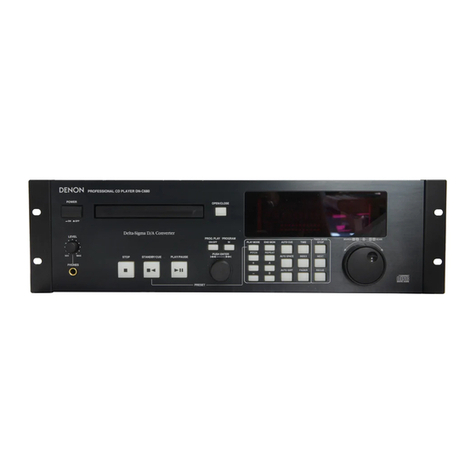
Nippon DENON DCD-1560 User manual

DENON
_.......
SERVICE
MANUAL
STEREO
CD
PLAYER
MIODEL
DCD-
1560
OPERATING
INSTRUCTIONS...
20.
cee
eet
e
ee
t
eee
e
nee
nner
neeees
SPECIFICATIONS
1.0...
cece
ee ce
eee
cece
ee
eee
een
ne
tenner
eee
n
rene
ae
nena
rene
nets
15
NOTE
FOR
HANDLING
OF
LASER
PICK-UP
.... 0...
ccc
e
ee
eee
eee
eee
ent
e
teen
enes
16~17
DISASSEMBLY
.......
cece
ccc
ee
eee
cee
ee
eee
eee
tent
tenance
tenet
n
ene
ee
enna
ee se
eeins
18
ADJUSTMENT
2...
....
cee
cc
eee
eee
eee
e
ee
ee
eee
nee
e
eee
e
eee
en
sere
een
een
enes
20~26
HEAT
RUN
MODE
FUNCTION
....
0...
cece
eect
eee
eee
tere
ene
ener
n
teens
27
IC
TERMINAL
FUNCTION
LIST
2.2.2...
eee
ee
eee
eee
eee
tent
n
tte
e
eee
n
nee
28~33
PARTS
LIST
OF
PW.BOARD
....
2.0.2
e
eee
cee
tee
ene
eee
eee
enter
a
a
eee
e
rene
eee
34,35
EXPLODED
VIEW
OF
MECHA
UNIT...
eee
cece
eee
ee
tenn
eee ent
n
nent
n
ene
36
”
PARTS
LIST
OF
MECHA
UNIT
......
0.02.
e
eee
eee
eee
ee ee
eee
een
e
tener
eee
e
seen
saeeenee
37
PARTS
LIST
OF
EXPLODED
VIEW...
ee
eee
ere
eee
eee
etter
eee
e
eee
e
ere
een
etes
38
PARTS
LIST
OF
PACKING
&
ACCESSORIES...
1.
cece
ene
n
eee
ene
38
EXPLODED
VIEW
..........--+-5
DREAMT
RARE
AS
a
bee
ea
Ma
Peaks
Bene
owed
ee
Ee
STANT
ES
39
PW.BOARD:
2
ccc
ccc
meine
sens
ee
sa
GU
EMCS
GER
ERE
SESE
Sheree
ee
Meee
mE
TREE
40~41
WIRING
DIAGRAM...
wc
ec
eee
tte
e
eee
e
eee
n
ene
tener
cnn
rerneees
Sea
42
SCHEMATIC
DIAGRAM
........
0-0
ee
cc
ce
ne
ce
eee
een
e
nee
e
ee ee
ene
e
nee
e
ete
es
43
SEMICONDUCTORS
.......-.
600
c
eee
ene
tne
Sid
hall
sh
aed
oe
eRe
Sa
cere
meas
LW ER
44
NIPPON
COLUMBIA
CoO,
LTD.

IMPORTANT
TO
SAFETY
WARNING:
TO
PREVENT
FIRE
OR
SHOCK
HAZARD,
DO
NOT
EXPOSE
THIS
APPLIANCE
TO
RAIN
OR
MOISTURE.
CAUTION:
1.
Handle
the
power
supply
cord
carefully
Do
not
damage
or
deform
the
power
supply
cord.
if
it
is
damaged
or
deformed,
it
may
cause
electric
shock
or
malfunction
when
used.
When
removing
from
walt
outlet,
be
sure
to
remove
by
holding
the
plug
attachment
and
not
by
pulling
the
cord.
2.
Do
not
open
the
top
cover
In
order
to
prevent
electric
shock,
do
not
open
the
top
cover.
If
problems
occur,
contact
your
DENON
DEALER.
3.
Do
not
place
anything
inside
Do
not
place
metal
objects
or
spill
liquid
inside
the
CD
player.
Electric
shock
or
malfunction
may
result.
Please,
record
and
retain
the
Model
name
and
serial
number
of
your
set
shown
on
the
rating
label.
Model
No.
DCD-1560
Seriat
No.
CAUTION
RISK
OF
ELECTRIC
SHOCK
DO
NOT
OPEN
CAUTION:
TO
REDUCE
THE
RISK
OF
ELECTRIC
SHOCK,
DO
NOT
REMOVE
COVER
(OR
BACK).
NO
USER
SERVICEABLE
PARTS
INSIDE.
REFER
SERVICING
TO
QUALIFIED
SERVICE
PERSONNEL.
The
lightning
flash
with
arrowhead
symbol
within
an
equilateral
triangle
is
intended
to
alert
the
user
of
the
presence
of
uninsulated
“dangerous
voltage”
within
the
product’s
enclosure
that
may
be
of
sufficient
magnitude
to
constitute
a
risk
of
electric
shock
to
persons.
The
exclamation
point
within
an
equilateral
triangle
is
intended
to
alert
the
user
of
the
presence
of
important
operating
and
maintenance
(servicing)
instruction
in
the
literature
accompanying
the
ap-
pliance.
IMPORTANT
(BRITISH
MODEL
ONLY)
The
wires
in
this
mains
lead
are
coloured
in
accordance
with
the
following
code:
Blue:
Neutral
Brown:
Live
The
colours
of
the
wires
in
the
mains
lead
of
this
apparatus
may
not
correspond
with
the
coloured
markings
identifying
the
terminals
in
your
plug
proceed
as
follows.
The
wire
which
is
coloured
blue
must
be
connected
to
the
terminal
which
is
marked
with
the
letter
N
or
coloured
black.
The
wire
which
is
coloured
brown
must
be
connected
to
the
terminal
which
is
marked
with
the
letter
L
or
coloured
red.
NOTE:
This
CD
player
uses
the
semiconductor
laser.
To
allow
you
to
enjoy
music
at
a
stable
operation,
it
is
recommended
to
use
this
in
a
room
of
5°C
-
35°C.
LABELS
(for
u.s.A.
mederoniy”
CERTIFICATION
|ODUCT
COMPILES
WITH
DHHS
RULES:
21
CFA
BUBCHAPTER
J
APPLICABLE
AT
DATE
OF
MANUFACTURE,
oro
es
DENON
OMe
CAUTION:
USE
OF
CONTROLS
OR
ADJUSTMENTS
OR
REFORMANCE
OF
PROCE-
DURES
OTHER
THAN
THOSE
SPECIFIED
HEREIN
MAY
RESULT
IN
HAZARDOUS
RADIATION
EXPOSURE.
THE
COMPACT
DISC
PLAYER
SHOULD
NOT
BE
ADJUSTED
OR
REPAIRED
BY
ANYONE
EXCEPT
PROPERLY
QUALIFIED
SERVICE
PERSONNEL.
~——
NOTE:
.
This
unit
may
cause
interference
to
radio
and
television
reception
if
you
do
not
operate
it
in
strict
accordance
with
this
OPERATING
INSTRUCTIONS.
This
unit
complies
with
Class
B
computing
device
rules
in
accord-
ance
with
the
specifications
in
Sub-part
J
or
Part
15
of
the
FCC
Rules,
which
are
designed
to
provide
reasonable
protection
against
such
interference
in
a
residential
installation.
If
the
unit
does
cause
interference
to
any
radio
or
television
reception,
try
to
reduce
it
by
one
or
more
of
the
following
means:
a)
Turn
the
other
unit
to
improve
reception
b)
Move
this
unit
c)
Move
this
unit
away
from
others
d)
Plug
this
unit
respectively
into
a
different
AC
outlet
*
This
is
note
in
accordance
with
Section
15.838
of
the
FCC
Rules.

6A.
10.
11.
SAFETY
INSTRUCTIONS
Read
Instructions
—
All
the
safety
and
operating
instructions
should
be
read
before
the
appliance
is
operated.
Retain
Instructions
—
The
safety
and
operating
instructions
should
be
retained
for
future
reference.
Heed
Warnings
—
All
warnings
on
the
appliance
and
in
the
operating
instructions
should
be
adhered
to.
Follow
Instructions
—
All
operating
and
use
instruc-
tions
should
be
followed.
Water
and
Moisture
-
The
appliance
should
not
be
used
near
water
—
for
example,
near
a
bathtub,
washbowl,
kitchen
sink,
laundry
tub,
in
a
wet
basement,
or
near
a
swimming
pool,
and
the
like.
Carts
and
Stands
—
The
appliance
should
be
used
only
with
a
cart
or
stand
that
is
recommended
by
the
manufacturer.
An
appliance
and
cart
combination
should
be
moved
with
care.
Quick
stops,
excessive
force,
and
uneven
surfaces
may
cause
the
appliance
and
cart
combination
to
overturn.
Wall
or
Ceiling
Mounting
—
The
appliance
should
be
mounted
to
a
wall
or
ceiling
only
as
recommended
by
the
manufacturer.
Ventilation
—
The
appliance
should
be
situated
so
that
its
location
or
position
does
not
interfere
with
its
proper
ventilation.
For
example,
the
appliance
should
not
be
situated
on
a
bed,
sofa,
rug,
or
similar
surface
that
may
block
the
ventilation
openings;
or,
placed
in
a
built-in
installation,
such
as
a
bookcase
or
cabinet
that
may
impede
the
flow
of
air
through
the
ventilation
openings.
Heat
—
The
appliance
should
be
situated
away
from
heat
sources
such
as
radiators,
heat
registers,
stoves,
or
other
appliances
(including
amplifiers)
that
produce
heat.
Power
Sources
—
The
appliance
should
be
connected
to
a
power
supply
only
of
the
type
described
in
the
operating
instructions
or
as
marked
on
the
ap-
pliance.
Grounding
or
Polarization
—
The
precautions
that
should
be
taken
so
that
the
grounding
or
polarization
means
of
an
appliance
is
not
defeated.
EXAMPLE
OF
ANTENNA
GROUNDING
ACCORDING
TO
NATIONAL
ELECTRICAL
CODE
INSTRUCTIONS
CONTAINED
IN
ARTICLE
810
-
“RADIO
AND
TELEVISION
EQUIPMENT”
‘To
exTunwas
anTenmea,
mSHAVICE
GROUNDING
ARRMGNALS
OF
tercragge
391
04
sere)
lat
ee
ee
GaouNd
mate.
GROUND
CLAMAE
BONDING
JuMePEAs
TIONAL
ANTENNA
GROUNDING
ELECTRODE
\e
Vile
a
FEET
(2
46
ml
WTO
THO
GARTH
ALQUIRED
By
LOCAL
COOKE
BEE
MEC
sme
IC
TION
810
-
210
12.
13.
14.
15.
16.
17.
18.
19.
20.
Power-Cord
Protection
—
Power-supply
cords
should
be
routed
so
that
they
are
not
likely
to
be
walked
on
or
pinched
by
items
placed
upon
or
against
them,
paying
particular
attentior™
to
cords
at
plugs,
con-
venience
receptacles,
and
the
point
where
they
exit
from
the
appliance.
Protective
Attachment
Plug
—
The
appliance
is
equip-
ped
with
an
attachment
plug
having
overload
pro-
tection.
This
is
a
safety
feature.
See
Instruction
Manual
for
replacement
or
resetting
of
protective
device.
If
replacement
of
the
plug
is
required,
be
sure
the
service
technician
has
used
a
replacement
plug
specified
by
the
manufacturer
that
has
the
same
overload
protection
as
the
original
plug.
Cleaning
—
The
appliance
should
be
cleaned
only
as
recommended
by
the
manufacturer.
Power
Lines
—
An
outdoor
antenna
should
be
located
away
from
power
lines.
Outdoor
Antenna
Grounding
—
If
an
outside
antenna
is
connected
to
the
receiver,
be
sure
the
antenna
system
is
grounded
so
as
to
provide
some
protec-
tion
against
voltage
surges
and
built
up
static
charges.
Section
810
of
the
National
Electrical
Code,
ANSI/NFPA
No.
70-1984,
provides
information
with
respect
to
proper
grounding
of
the
mast
and
sup-
porting
structure,
grounding
of
the
lead-in
wire
to
an
antenna
discharge
unit,
size
of
grounding
conduc-
tors,
location
of
antenna-discharge
unit,
connection
to
grounding
electrodes,
and
requirements
for
the
grounding
electrode.
See
Figure
A.
Nonuse
Periods
—
The
power
cord
of
the
appliance
should
be
unplugged
from
the
outlet
when
left
unused
for
a
long
period
of
time.
Object
and
Liquid
Entry
—
Care
should
be
taken
so
that
objects
do
not
fall
and
liquids
are
not
spilled
into
the
enclosure
through
openings.
Damage
Requiring
Service
—
The
appliance
should
be
serviced
by
qualified
service
personnel
when:
A.
The
power-supply
cord
or
the
plug
has
been
damaged;
or
B.
Objects
have
fallen,
or
liquid
has
been
spilled
into
the
appliance;
or
C.
The
appliance
has
been
exposed
to
rain;
or
D.
The
appliance
does
not
appear
to
operate
normal-
ly
or
exhibits
a
marked
change
in
performance;
or
E.
The
appliance
has
been
dropped,
or
the
enclosure
damaged.
Servicing
—
The
user
should
not
attempt
to
service
the
appliance
beyond
that
described
in
the
operating
instructions.
All
other
servicing
should
be
referred
to
qualified
service
personnel.
Use
No.
10
AWG
(5.3
mm?)
copper,
No.
8
AWG
(8.4
mm?}
aluminum,
No.
17
AWG
(1.0mm?)
copper-clad
steel
or
bronze
wire,
or
larger,
as
a
ground
wire.
Secure
antenna
lead-in
and
ground
wires
to
house
with
stand-off
insulators
spaced
from
4-6
feet
(1.22-1.83
m)
apart.
Mount
antenna
discharge
unit
as
close
as
possible
to
where
lead-in
enters
house.
Use
jumper
wire
not
smaller
than
No.
6
AWG
(13.3
mm?)
copper,
or
the
equivalent,
when
a2
separate
antenna-
grounding
electrode
is
used.
See
NEC
Section
810-21
(j).
i
i
i
t
:

NOTE
ON
USE
Be
careful
of
high
temperatures
e
Do
not
place
the
set
in
a
location
where
it
will
be
exposed
to
direct
sunlight
or
near
a
heating
ap-
pliance.
Caution
on
rack/cabinet
installation
e
Avoid
installing
the
set
in
a
closed-
type
rack.
e
When
installing
in
a
rack
or
cabinet,
provide
a
sufficiently
large
ventilation
opening
to
promote
heat
radiation.
Do
not
allow
foreign
matter
into
the
equipment
e
Be
especially
careful
of
needles,
hair
pins,
and
coins
getting
into
the
set.
Caution
on
humidity,
water,
and
dust
e
Do
not
place
the
set
in
a
location
where
there
is
high
humidity
or
a
lot
of
dust.
Flower
vases
or
other
items
con-
taining
water
should
not
be
placed
on
top
of
the
set.
Care
of
the
case
e
Avoid
the
use
of
pesticides
near
the
set
as
well
as
wiping
the
case
with
benzine,
thinner
or
other
sol-
vents
since
they
may
cause
a
change
in
quality
or
color.
Use
a
soft
cloth
when
wiping
away
dirt
and
follow
the
instructions
careful-
ly
when
using
chemically
treated
cloths.
Care with
the
power
cord
e@
When
removing
the
plug
from
the
receptacle,
do
not
pull
the
power
cord;
be
sure
to
hold
the
plug
when
removing
it.
Do
not
open
the
case
e
Opening
the
top
cover
or
the
bot-
tom
plate
of
the
case
and
inserting
your
hand
is
dangerous.
Do
not
open
the
case.
If
some
trouble
arises
with
the
performance
of
the
set,
remove
the
power
plug
soon
and
contact
the
store
where
the
set
was
purchased
or
a
nearby
dealer.
During
your
absence
e@
When
not
using
the
set
for
an
extended
period
such
as
when
tak-
ing
a
trip,
be
sure
to
disconnect
the
plug
from
the
receptacle.
For
sets
with
ventilation
holes
Do
not
block
the
ventilation
holes
of
the
set
e
Blocking
of
the
ventilation
holes
will
lead
to
damage
of
the
set.
The
ventilation
holes
are
very
im-
portant
for
‘heat
radiation
from
within
the
set.
Care
must
be
taken
since
placing
an
object
against
the
holes
will
result
in
an
extreme
rise
of
temperature
within
the
set.

Thank
you
for
purchasing
this
DENON
Compact
Disc
Player.
Please
read
the
operating
instructions
thoroughly
in
order
to
acquaint
yourself
with
the
CD
player
and
achieve
maximum
satisfaction
from
it.
—
TABLE
OF
CONTENTS
—
FEATURES
NAMES
AND
FUNCTIONS
OF
PARTS
..
6~7
CONNECTION)...
cscsevoscosesersoissesvsssescdnscvstsesentsseasstocacsevesseseseecebsstesgoengeysjorseesesets
8
OPENING
AND
CLOSING
THE
DISC
HOLDER
AND
LOADING
A
DISC
........
8
NORMAL
CD
PLAYBACK
ADVANCED
CD
PLAYBACK
...
TIMER-CONTROLLED
PLAYBACK
..
=
11
THE
COMPACT
DISC
.....
ce
ecseesecssterseereseeee
wee
12
PLAYBACK
USING
THE
REMOTE
CONTROL
UNIT...
12
~
13
INSTALLATION
PRECAUTIONS
.........
13
TROUBLESHOOTING
we
14
SPECIFICATIONS.
..0..escecssccssssstsceeerseseneeeeeeeesensenseceey
sessovesssueninovedpnoonseusseeontoge
14
Please
check
to
make
sure
the
following
items
are
included
with
the
main
unit
in
the
carton:
(1)
Operating
Instructions
(2)
Connection
Cord
{3)
Remote
Control
Unit
RC-211
...
(4)
Mini
Screwdriver
FEATURES
The
DCD-1560
is
a
CD
player
which
uses
DENON’s
unique
AS.L.C.
(Super
Linear
Converter)
for
eliminating
loss
of
Sqeedsquality
in
the
PCM
playback
section
to
offer
playback
of
the
same
sounds
as
those
in
the
studio
or
hall
where
the
CD
was
recorded.
In
addition,
the
use
of
carefully
selected
parts
makes
this
a
high
performance
CD
player
reproducing
the
original
sound
field
with
rich
musical
expression.
(1)
Real
20-bit
AS.L.C.
(Super
Linear
Converter)
The
use
of
DENON’s
unique
system
for
preventing
zero
cross
distortion,
the
main
factor
in
loss
of
sound
quality
in
the
PCM
playback
section,
plus
real
20-bit
D/A
converters
with
superior
resolution,
offers
reproduction
of
the
original
sound
field
with
rich
musical
expression.
(2)
High
performance
digital
filter
The
independent
real
20-bit
D/A
converters
for
the
left
and
right
channels
and
a
high
precision
digital
filter
with
8
times
oversampling
bring
out
the
best
of
the
analog
filter
to
produce
crisp,
clear
sound.
(3)
Remote
control
unit
with
volume
control
In
addition
to
such
functions
as
play,
pause,
stop
and
direct
search
using
number
buttons,
the
remote
control
unit
also
includes
+
and
—
volume
buttons
for
remote
control
of
the
volume.
The
remote
control
functions
greatly
add
to
the
operability
of
the
set.
(4)
Optical
digital
output
This
jack
makes
it
possible
to
output
the
data
on
the
compact
disc
in
its
digital
form
to
a
digital
processor
or
D/A
unit
for
playback.
The
optical
output
eliminates
noise
interference
and
improves
sound
quality.
(5)
Great
Resistance
to
Vibration
BMC,
a
material
with
excellent
vibration-absorbing
properties,
is
used
for
the
installation
base
of
the
laser
pickup,
and
the
double-layered
top
cover
and
bottom
panels
increase
rigidity
and
improve
resistance
to
vibration.
(6)
Simple
Playback
of
8
cm
CD
Singles
8cm
CD
signals
can
be
played
without
using
an
adaptor.
screwdriver.
e
Line
Voltage
Selection
(for
multiple
voltage
model
only)
*
The
desired
voltage
may
be
set
with
the
VOLTAGE
SELECTOR
knob
on
the
rear
panel,
using
a
*
Do
not
twist
the
VOLTAGE
SELECTOR
knob
with
excessive
force
as
this
may
cause
damage.
*
If
the
VOLTAGE
SELECTOR
knob
does
not
turn
smoothly,
please
contact
a
qualified
serviceman.
4
VOLTAGE.
SELECTOR
BEFORE
USING
—
Be
sure
to
release
the
shipping
lock.
Shipping
lock
Ve
LOCK
FREE
/
Mini
screwdriver
CAUTION
Be
sure
to
release
the
shipping
lock
on
the
bottom
panel
before
turning
the
power
on.
When
locking
or
freeing
the
shipping
lock,
be
sure
to
set
the
player
with
the
front
panel
facing
up,
the
back
panel
facing
down.
(Refer
to
the
diagram)
e@
Shipping
lock
The
shipping
lock
keeps
the
lasr
pickup
inside
the
player
from
moving
during
shipment.
e
When
using
the
player
Before
turning
the
power
on,
be
sure
to
turn
the
player
up
so
that
the
back
panel
is
facing
down,
insert
the
included
mini
screwdriver
into
the
shipping
lock,
then
turn
counterclockwise
(in
the
FREE
direction)
unit
it
stops.
Be
sure
the
lock
is
in
this
position
when
using
the
player.
e
Reshipping
(1)
Turn
the
power
on,
open
the
disc
holder,
check
that
no
disc
is
loaded,
then
close
the
disc
holder.
(2)
Turn
the
power
off,
set
the
player
up
so
that
back
panel
is
facing
down,
then
use
the
mini
screwdriver
and
turn
the
shipping
lock
clockwise
(in
the
LOCK
direction)
until
it
stops.

NAMES
AND
FUNCTIONS
OF
PARTS
@
Open/Close
Button
(
&
0
12)
®
96
DENOW
ros
sco
moenocy
commact
osc
marten
DCD
1560
4
©6@O0
®@
O2@
Be
88
88
8S
moos
1234S
ET
EPOURANE
S|
a
ee
ee
a
=
qin
oa
neue
|
=
—
AUTOLO
AUTO
SPACE
fueDOU
pour
mat
tees
noel
oath]
S|
7
I
3h
Lie)
QPTICAL
=
COAXIAL
Lower
Switch
(POWER)
When
the
power
is
turned
on,
“(00)”
appears
on
the
TRACK
NO.
display,
and
if
no
disc
is
loaded,
"(00220000)"
appears
on
the
digital
display
and
the
calendar
lights
after
a
few
seconds.
e
If
the
power
is
turned
on
with
a
disc
already
loaded,
the
total
number
of
tracks
on
the
disc
is
displayed
on
the
TRACK
NO.
display,
the
total
time
is
displayed
on
the
TIME
display,
the
numbers
on
the
music
calendar
light
up
to
the
number
of
tracks
on
the
disc,
and
playback
begins.
Disc
Holder
e
Place
the
disc
on
the
disc
holder
with
the
label
facing
up.
e
Use
the
open/close
button
(
44
OPEN/CLOSE)
@
to
open
and
close
the
disc
holder.
e
The
disc
holder
may
also
be
closed
by
pressing
the
play
button
(
>
PLAY)
@
or
pause
button
(Il
PAUSE)
@.
Remote
Control
Sensor
e
This
sensor
receives
the
infrared
light
transmitted
from
the
wireless
remote
control
unit.
e
For
remote
control,
point
the
supplied
remote
control
unit
RC-211
towards
this
sensor.
e
When
a
signal
is
transmitted
from
the
remote
control
unit,
the
remote
control
indicator
in
the
display
@
will
light
up
briefly.
Display
e
The
digital
display
is
divided
into
sections,
such
as
displays
for
track
number,
index,
playback
time
and
calendar,
as
shown
below.
Pause
indicator
Auto
space
pity
edit
Play
indicator
indicator
indicator
.
Remote
control
Emphasis
indicator indicator
Total
remaining
Calendar
time
indicator
Program
indicator
indicator
Current
track
Time
search
Random
remaining
time
jndicator
indicator
indicator
OPEN/CLOSE)
e
The
disc
holder
is
opened
and
closed
by
pressing
this
button.
e
Press
this
button
once
to
open
the
disc
holder,
and
once
again
to
close
it.
e@
When
the
disc
holder
is
closed
with
a
disc
loaded,
the
disc
will
rotate
for
a
couple
of
seconds
while
the
disc
contents
are
read.
The
number
of
tracks
and
total
playback
time
on
the
disc
are
then
displayed
on
the
digital
display
3.
C6)
3)
19)
Auto
Edit
Button
(AUTO
EDIT)
e
The
tracks
on
the
CD
are
automatically
split
into
two
halves,
Side
A
and
Side
B,
fike
an
analog
disc,
with
the
division
at
the
place
between
tracks
which
is
closest
to
1/2 the
total
playing
time.
e
When
this
button
is
pressed
in
the
stop
mode,
the
[AUTO
EDIT_]
indicator
lights,
and
the
total
playing
time
for
the
first
half
and
the
track
numbers
on
the
calendar
are
displayed
for
approximately
2
seconds.
Next,
the
same
is
done.
for
the
second
half,
after
which
the
unit
is
automatically
Set
to
the
pause
mode
at
the
beginning
of
the
first
track.
When
the
PLAY
or
PAUSE
button
is
pressed,
playback
begins,
and
the
unit
is
automatically
set
to
the
pause
mode
at
the
beginning
of
the
first
track
of
the
second
half
which
was
previously
displayed.
When
the
PLAY
or
PAUSE
button
is
pressed
again,
playback
resumes,
and
the
unit
is
automatically
set
to
the
stop
mode
at
the
end
of
the
last
track
on
the
disc,
at
which
time
the
indicator
turns
off.
e
This
function
will
only
work
for
discs
with
a
total
of
20
tracks
or
less.
Also,
when
this
function
is
used
the
mode
is
automatically
set
to
the
program
mode,
so
direct
search
is
not
possible.
e
The
indicator
turns
off
and
the
auto
edit
function
is
cleared
when
the
OPEN/CLOSE,
STOP
OR
PROG/DIRECT
button
is
pressed.
e
The
data
for
the
total
playing
time
recorded
on
the
disc
and
the
actual
total
playing
time
of
the
tracks
differ,
so
there
may
bea
difference
between
the
time
displayed
in
the
stop
mode
(the
total
playing
time)
and
the
total
of
the
times
of
the
first
and
second
halves
in
the
auto
edit
mode
(about
2
seconds).
parte
Space
Button
(AUTO
SEACE)
Pressing
this
button
will
cause
the
indicator
to
light
and
a
blank
space
of
approximately
4
seconds
is
inserted
between
tracks
during
CD
playback.
Pressing
the
button
once
more,
the
indicator
goes
out
and
the
Auto
Space
feature
is
cancelled.
e
When
one
of
the
track
search
buttons
(
I€q@
or
DPI)
is
pressed,
the
Auto
Space
function
will
not
operate.
e@
The
Auto
Space
function
will
work
during
normal
playback
as
well
as
programmed
playback.
e
Although
4-second
blanks
are
inserted
between
tracks,
this
additional
time
is
not
reflected
by
the
indication
on
the
time
remaining
display
or
time
display
when
the
Auto
Edit
function
is
engaged.
:
Random
Play
Button
(RANDOM)
e
Press
this
button
to
repeat
play
the
tracks
on
the
disc
in
random
order.
Repeat
All
Tracks
Button
(ALL)
e
Press
this
button
to
repeat
playback
of
all
tracks.

e
@
@®
=)
When
this
button
is
pressed,
lights
on
the
display
and
all
tracks
on
the
disc
or
in
a
program
will
be
repeatedly
played
back.
Press
this
button
once
more
to
disengage
the
Repeat
All
function.
1-track
Repeat
Button
(1)
e
Press
this
button
to
repeat
one
track
only.
When
pressed
during
playback,
the
track
currently
playing
is
repeated.
Pisplay
Button
(DISPLAY)
Press
this
button
to
turn
the
indicators
on
the
display
window
off.
@
When
pressed
once,
only
the
track
number,
index
number,
and
time
will
remain
lit.
e@
When
pressed
again,
all
indicators
are
turned
off,
and
only
the
track
number
will
be
displayed
except
during
‘playback.
Time
Mode
Button
(TIME)
This
button
is
used
to
select
the
desired
indication
on
the
TIME
display.
The
indication
on
this
display
will
change
each
time
the
button
is
pressed.
Normally,
the
elapsed
playback
time
of
the
current
track
is
displayed.
Pressing
the
button
once,
CSINGLE
]
is
displayed
and
the
remaining
time
of
the
current
track
is
displayed.
Pressing
once
more,
is
displayed,
and
total
playing
time
of
remaining
tracks
is
displayed.
However,
when
program-
med
play
is
in
progress,
the
total
remaining
time
of
the
program
is
displayed.
Press
the
button
once
again
to
return
to
the
normal
display
of
the
elapsed
playback
time
of
the
current
track.
Time
Search
Button
(TIME
SEARCH)
e
Use
this
button
to
indicate
the
playback
starting
time
or
to
specify
a
section
between
two
points
for
playback.
(Refer
to
Page
10)
Program/Direct
Button
(PROG/DIRECT)
e
Press
this
button
to
switch
between
the
program
and
direct
modes
when
setting
the
program
memory
or
using
direct
search.
(Refer
to
Page
9)
Humber
Buttons
(1,
2, 3, 4, 5, 6,
7,
8,
9
and
0)
Use
these
buttons
for
the
direct
search
and
program
memory
functions.
For
direct
search,
press
for
example
button
[3]
if
you
want
to
hear
track
number
3.
For
track
number
12,
press
[+10
]
then
[2].
To
program
tracks,
press
the
PROG/DIRECT
button
to
set
to
the
program
mode.
+10
Button
(+10)
e
Press
this
button
first
when
selecting
track
numbers
over
10.
Use
it
together
with
the
number
buttons.
For
example,
to
select
track
number
@®,
press
then
6].
For
track
number
33,
press
three
times,
then
press
[0].
Clear
Button
(CLEAR)
e
Use
this
to
correct
programmed
tracks.
(Refer
to
Page
9)
Call
Button
(CALL)
e
Press
this
button
to
check
the
tracks
which
have
been
prog-
rammed.
Index
Button
(INDEX)
e
Press
this
button
to
start
playback
from
an
index
within
a
track.
Use
the
number
buttons
to
specify
the
index
number.
play
Button
(
>»
PLAY)
Press
this
button
to
start
gegen
oF
a
disc.
e
When
this
button
is
pressed,
[J
is
displayed,
and
the
track
number
being
played
is
displayed
together
with
the
elapsed
playback
time
of
the
track.
e
Tracks
are
shown
on
the
calendar
display.
Once
a
track
has
been
played,
the
corresponding
track
number
goes
out
on
the
calendar
display.
Pause
Button
(
Il
PAUSE)
e
Press
this
button
to
stop
playback
temporarily.
i)
e
If
this
button
is
pressed
during
playback,
playback
is
stopped.
temporarily,
the
[>
PLAY]
indicator
goes
out
and
the
[HTPAUSE
|
indicator
lights.
e
Press
this
button
or
the
play
button
(
»
PLAY)
again
to
continue
playback.
7"
nd
Stop
Button (
STOP)
Press
this
button
to
stop
playback.
The
disc
will
stop
rotating,
and
the
number
of
tracks
and
total
playing
time
of
the
disc
are
displayed
on
the
TRACK
NO.
and
TIME
displays,
respectively.
e
Incase
programmed
playback
is
engaged
when
this
button
is
pressed,
the
number
of
tracks
and
total
playing
time
of
the
program
are
displayed.
e
If
this
button
is
pressed
in
the
stop
mode,
the
program
memory
is
cleared.
Automatic
Search
Reverse
Button
(
I€q
)
e
Press
this
button
to
return
the
pickup
to
the
beginning
of
the
present
track.
Press
again
to
return
to
other
tracks.
e
By
pressing
the
button
a
number
of
times,
the
pickup
will
move
back
the
corresponding
number
of
tracks.
Automatic
Search
Forward
Button
(
PPI)
e
Press
this
button
to
move
the
pickup
forward
to
the
beginning
of
the
next
track.
Press
again
to
move
ahead
to
other
tracks.
e
By
pressing
the
button
a
number
of
times,
the
pickup
will
advance
the
corresponding
number
of
tracks.
Manual
Search
Reverse
Button
(
44
)
e
Press
this
button
during
playback
for
fast
reverse
search.
As
long
as
the
button
is
kept
pressed,
music
signals
are
played
back
faster
than
normal.
e
Pressing
this
button
when
the
pause
mode
is
engaged,
you
can
quickly
reverse
the
pickup
to
a
desired
position,
three
times
faster
compared
to
manual
reverse
search
during
playback.
During
this
time,
no
sound
is
heard.
Manual
Search
Forward
Button
(
D>
)
e
Press
this
button
during
playback
for
fast
forward
search.
As
long
as
the
button
is
kept
pressed,
music
signals
are
played
back
faster
than
normal.
e
Pressing
this
button
when
the
pause
mode
is
engaged,
you
can
quickly
forward
the
pickup
to
a
desired
position,
three
times
faster
compared
to
manual
forward
search
during
playback.
During
this
time,
no
sound
is
heard.
Headphones
Jack
(PHONES)
e
For
private
listening,
you
can
connect
your
headphones
to
this
jack.
Do
not
raise
the
volume
level
too
much
when
listening
through
headphones.
(Headphones
are
sold
separately.)
Volume
Control
(LINE
OUT/PHONES
LEVEL)
e
Use
this
to
adjust
the
output
level
(VOLUME)
of
the
headphones
or
line
output
(VARIABLE).
@
The
same
operation
is
possible
using
the
included
remote
control
unit.
(See
Page
13)
Digital
Output
Switch
(DIGITAL
OUTPUT)
e
Use
this
switch
to
turn
the
signals
from
the
digital
output
jacksk
(
@
and
@
below)
on
and
off.
e
When
off,
no
digital
signals
are
output.
Output
Terminal
(FIX-VARIABLE)
e
Connect
these
jacks
to
the
input
jacks
on
your
amplifier.
(Refer
to
Page
8
for
details
on
the
connections.)
Digital
Output
Jack
(OPTICAL)
e
Outputs
digital
optically.
Digital
Output
Jack
(COAXIAL)
e
This
jack
outputs
digital
data.
e
Werecommend
using
a
75-ohm
pin
cord
(available
in
stores)
for
connections.
Continuous
Operation
If
the
automatic
search
reverse
button
@,
the
automatic
search
forward
button
@),
the
CALL
button
®,
or
the
+10
button
@
are
held
in,
the
function
of
that
button
will
be
repeated.
fl
i
i
}
i
,

CONNECTION
(1)
Connecting
the
Output
Terminal
(FIX-VARIABLE)
Use
the
included
pin
cords
to
connect
the
left
(L)
and
right
(R)
output
terminal
(FIX-VARIABLE)
of
the
DCD-1560
to
the
CD,
AUX,
or
TAPE
PLAY
left
(L)
and
right
(R)
input
jacks
of
the
amplifier.
There
are
two
types
of
output
jacks,
one
of
the
variable
type
and
one
of
the
fixed
type.
Be
sure
to
use
the
variable
outputs
if
you
want
to
be
able
to
control
the
output
level
from
the
DCD-1560.
DCD-1560
K——<
Power
outlet
(Amplifier)
(2)
Connecting
the
Digital
Output
Jack
(COAXIAL/
OPTICAL)
Use
a
75-ohm
pin
cord
to
connect
the
digital
output
jack
(COAXIAL)
of
the
DCD-1560
to
the
digital
input
jack
(COAXIAL)
on
a
digital
processor
or
D/A
unit,
available
in
stores.
In
the
same
way,
connect
the
digital
output
jack
(OPTICAL)
on
the
DCD-1560
with
the
optical
input
on
a
digital
processor
or
D/A
unit
using
an
optical
fiber
cable.
DCD-1560
Power
outlet
Digital
processor
or
D/A
unit
Power
outlet
DIGITAL
INPUT
COAXIAL
°
|
OPTICAL
o-
Connection
Precautions
e
Before
proceeding
with
connections
or
disconnections
of
cables
and
power
cords,
be
sure
to
turn
all
system
components
off.
e
Ensure
that
all
cables
are
connected
properly
to
the
L
(left)
and
R
(right)
jacks.
e
insert
plugs
fully
into
the
terminals.
:
e
Connect
the
output
jacks
to
the
amplifier
CD,
AUX
or
TAPE
PLAY
input
jacks.
OPENING
AND
CLOSING
THE
DISC
HOLDER
AND
LOADING
A
DISC
Opening
and
closing
the
disc
holder
(This
operation
only
works
while
the
power
is
on.)
1.
Press
the
power
switch
(POWER)
to
turn
on
the
power.
2.
Press
the
open/close
button
(
OPEN/CLOSE).
How
to
load
a
disc
e
Make
sure
the
disc
holder
is
completely
open.
e
Hold
the
disc
by
the
edges
and
place
it
on
the
disc
tray.
(Do
not
touch
the
signal
surface,
i.e.,
the
glossy
side.)
e
When
using
12
cm.
diameter
discs,
make
sure
the
outer
edge
matches
the
tray
guide
circumference
(Fig.
1),
and
when
using
CD
singles
(8
cm.
diameter)
match
the
outer
edge
with
the
inner
tray
guide
circumfer-
ence.
(Fig.
2)
e
Press
the
open/close
button
(
OPEN/CLOSE)
to
close
the
disc
holder.
‘
e®
When
the
disc
holder
is
closed,
the
disc
is
read
and
after
a
few
seconds
the
number
of
tracks
and
total
playing
time
are
displayed
on
the
TRACK
NO:
and
TIME
displays,
respectively.
?
@
When
the
disc
holder
is
open
and
a
disc
is
loaded,
you
may
also
press
the
play
(
»
PLAY)
or
pause
(
If
PAUSE)
button
to
close
the
disc
holder.
(If
the
play
button
(
®
PLAY)
is
pressed,
playback
will
start
immediately,
upon
the
disc
contents
having
been
read.)
Fig.
1
Trayaguide
eee
disc
12
cm
disc
SS.
aaa?
oe
Caution:
e
If
your
finger
should
get
caught
in
the
disc
holder
when
it
closes,
press
the
open/close
button
(
4
OPEN/CLOSE).
e
Donot
place
any
foreign objects
on
the
disc
tray,
and
do
not
place
more
than
one
disc
on
the
tray
at
a
time.
Otherwise
malfunction
may
occur.
e
Donot
push
in
the
disc
tray
manually
when
the
power
is
off
as
this
may
cause
malfunction
and
damage
the
CD
player.
NORMAL
CD
PLAYBACK
(1)
Starting
Playback
1
Press
the
power
switch
(POWER)
to
turn
on
the
power.
2
Load
the
disc
you
want
to
play.
e
When
the
disc
holder
is
closed,
the
disc
is
read
and
the
number
of
tracks
and
total
playing
time
of
the
disc
are
displayed.
3
Press
the
play
button
{
»
PLAY).
(2}
Stopping
Playback
(
HM
STOP)
1
Press
the
stop
button
(
li
STOP).
e
When
all
tracks
have
been
played
on
a
disc,
playback
will
stop
by
itself.
—

i
i
t
a
j
\
:
4
}
“4
}
H
1
4
H
4
z
,
Precautions:
e
lf
no
disc
has
been
loaded
or
the
disc
is
loaded
upside
down,
the
track
number,
index,
and
time
indicators
will
all
display
“0”
and
the
entire
calendar
will
light.
e
When
the
information
on
the
disc
cannot
be
read
correctly,
for
example
due
to
dust
or
dirt
on
the
disc,
the
indicators
will
read
as
shown
below.
Nothing
will
be
shown
on
the
TRACK
NO. and
TIME
displays,
and
it
may
take
quite
a
while
to
read
the
disc.
e
When
PLAY,
PAUSE
or
NUMBER
buttons
are
pushed
just
after
turning
on
the
unit
with
a
disc
inserted,
the
“TRACK
INDEX
TIME
M
S”
display
might
not
be
indicated
in
the
window.
This
is
normal.
In
this
case,
push
the
STOP
button
to
light-up
the
display
and
then,
push
your
necessary
function
button.
Normal
display
Improper
display
ADVANCED
CD
PLAYBACK
1)
Playing
a
Specific
Track
Direct
Search
...............00
(Number
buttons)
e
Use
the
number
buttons
and
the
+10
button
to
input
the
number
of
the
desired
track.
For
example,
to
play
track
number
4,
press
[4]
,
and
to
play
track
number
12,
press
and
[2].
Playback
will
begin
from
that
track.
(2)
Advancing
to
the
next
track
during
playback
Press
the
Automatic
search
forward
button
(
PPI)
during
playback.
e
The
pickup
will
advance
to
the
beginning
of
the
next
track
and
playback
will
continue.
Pressing
the
button
several
times
will
forward
the
pickup
the
corresponding
number
tracks.
3]
Returning
to
the
beginning
of
the
current
track
during
playback
Press
the
Automatic
search
reverse
button
(
I€@
)
during
playback.
e
The
pickup
will
return
to
the
beginning
of
the
current
track
and
playback
will
continue.
Pressing
the
button
several
times
will
return
the
pickup
the
corresponding
number
tracks.
©
Finding
Sections
Within
a
Track
Arve
cain
dahon
ahs
asieen
tie
elena
gig
apts
foiinteben
ata
easiuaalcogalteaaa
tanned
Index
Search
e
With
this
function,
you
can
find
and
play
from
the
beginning
of
sections
within
the
track
marked
by
index
numbers.
(Number
buttons)
ONDEX)
(PROG
/
DIRECT)
@
“--"
appears
on
the
TRACK
NO.
display
when
the
INDEX
button
is
pressed.
@
Input
the
track
number
using
the
number
buttons.
Next,
“--”
appears
on
the
INDEX
display.
Input
the
desired
index
number,
and
playback
will
start
from
that
index
number.
For
example,
to
start
from
index
2
Otetedge
Number
3,
press
INDEX,
3,
then
2.
Indexes
e
Indexes
are
numbers
which
are
assigned
to
sections
within
a
track.
Check
the
disc’s
explanatory
notes
for
the
index
numbers.
e
If
you
input
an
index
number
not
on
the
disc,
playback
will
start
from
the
last
index
number
on
the
track.
8
Playing
Specific
Tracks
in
a
Specific
Order
0.0...
cccccseeccscseescseessceeeenaneceseansnes
Programmed
Play
e
With
this
function,
you
can
choose
any
of
the
tracks
on
the
disc
and
program
them
to
play
in
any
order.
;
e
Programming
is
possible
with
the
disc
holder
open.
e
Up
to
20
tracks
can
be
programmed.
e
The
programmed
tracks
are
shown
on
the
calendar.
{1}
Programming
(Number
buttons)
e
Press
the
PROG/DIRECT
button
so
that
the
indicator
lights,
then
use
the
number
buttons
and
the
+10
button
to
program
the
tracks.
For
example,
to
program
tracks
3,
12,
and
7,
press
[PROG/DIRECT],
(3),
[+10],
[2],
and
77.
The
corresponding
track
number
lights
on
the
calendar
each
time
a
track
is
programmed,
the
track
number
is
displayed
on
the
TRACK
NO.
display,
the
number
of
tracks
programmed
is
displayed
on
the
INDEX
display,
and
the
total
playing
time
of
the
programmed
tracks
is
displayed
on
the
TIME
display.
A
few
seconds
after
the
last
track
has
been
programmed,
the
total
number
of
tracks
programmed
is
display-
ed
on
the
TRACK
NO.
display
and
the
total
playing
time
of
the
programmed
tracks
is
displayed
on
the
TIME
display.
(2)
Checking
the
Programmed
Tracks
e
Press
the
CALL
button.
The
programmed
tracks
are
displayed
in
order
on
the
TRACK
NO.
display
each
time
the
CALL
button
is
pressed.
(3)
Playing
the
Programmed
Tracks
HSSse5555
6
6
o
e
Press
the
(
®
PLAY)
button
to
play
the
tracks
in
the
programmed
order.
(4)
Correcting
a
Programmed
Track
(CLEAR)
(Number
buttons)
©
To
correct
the
last
track
which
has
been
programmed,
press
the
CLEAR
button
then
program
the
track
correctly.
e
To
clear
a
track
in
the
middle
of
the
program,
press
the
CALL
button
to
recall
the
track,
then
press
CLEAR
button,
and
finally
press
STOP
button.
9

(5)
Clearing
the
Program
e
The
entire
program
is
cleared
when
the
PROG/DIRECT
button
is
pressed
again.
The
program
is
also
cleared
when
the
(
&
oPEN/
CLOSE)
button
is
pressed.
e
lf
the
PROG/DIRECT
button
is
pressed
during
programmed
play,
the
program
is
cleared
and
playback
continues
normally
through
to
the
last
track
on
the
disc.
NOTES
e
If
programming
is
done
in
the
play
or
pause
mode,
the
track
currently
playing
is
programmed
at
the
first
position.
Other
tracks
can
be
added
to
the
program,
but
the
number
of
programmed
tracks
and
the
playing
time
will
not
be
displayed.
Direct
search
is
not
possible
during
programmed
play.
If
the
number
buttons
are
pressed,
that
track
is
added
to
the
end
of
the
program.
Programming
is
possible
with
the
disc
holder
open. Track
numbers
greater
than
the
number
of
tracks
recorded
on
the
disc
can
be
programmed,
but
will
be
automatically
cleared
before
playback
begins.
The
remaining
time
per
track
will
only
be
displayed
for
track
numbers
1
through
20.
The
tota!
program
time
and
remaining
program
time
are
not
displayed
if
tracks
greater
than
track
number
20
are
prog-
rammed.
6]
Repeating
playback
of
alll
tracks
............::scsscsscescssserneeenee
Repeat
All
(
>
PLAY)
(ALL)
@
Press
the
repeat
all
button
(ALL),
@®
Press
the
play
button
(
»
PLAY).
e
Pressing
the
repeat
all
tracks
button
(ALL),
is
displayed.
Steps
(©
and
@
above
may
be
reversed.
To
cancel
repeat
playback
of
all
tracks,
press
the
repeat
all
button
(ALL)
once
more.
e
Pressing
the
repeat
all
button
(ALL)
during
programmed
playback,
playback
of
the
tracks
entered
into
the
memory
will
be
repeated.
e
Repeating
a
Single
Track
.........
ialheuiseavVivvacesevednazmadsbensnasiad
1-track
Repeat
(1)
e
Press
this
button
if
you
want
to
hear
a
track
repeatedly.
Press
1-track
repeat
button
(1)
The
track
is
repeated
continuously.
e
if
the
1-track
repeat
button
(1)
is
pressed
during
playback
of
a
disc
containing
20
tracks
or
less,
the
indicator
lights,
the
number
of
that
track
lights
on
the
calendar
and
that
track
is
played
repeatedly.
*
The
1-track
repeat
function
is
possible
if
there
are
more
than
20
tracks
on
the
disc,
in
which
case
only
the
indicator
lights
and
none
of
the
numbers
on
the
calendar
light.
10
e
if
the
1-track
repeat
button
(1)
is
pressed
in
the
stop
mode,
track
number
1
lights
on
the
calendar,
the
indicator
lights,
and
it
becomes
possible
to
repeat
only
one
track.
To
start,
press
the
(
>»
PLAY)
button.
e
Tocancel
1-track
repeat,
press.
thesser"ack
repeat
button
(1)
once
again.
Normal
playback
will
restinié;
with
the
normal
indicators
lit.
(3)
Playing
a
desired
time
or
SA
SIL
Senn
leg
ert
eeieeer
ener
e
With
this
function
you
can
specify
the
starting
time
and/or
ending
time
in
seconds,
allowing
playback
of
a
very
specific
section
of
a
track.
in
the
Stop
Mode
e
Specifying
the
starting
time
@
Press
the
TIME
SEARCH
button.
The
indicator
will
flash
on
the
display,
and
the
TRACK
display
will
read
“--”.
@
Use
the
number
buttons
to
set
in
order
the
track
number
and
the
time
(minutes
and
seconds).
Example:
Starting
from
2
minutes
34
seconds
into
track
3
Press
the
following
buttons
in
order:
[TIIME
SEARCH_1],
[0],
BI,
[0],
2],
(3),
(4.
NOTE:
If
a
track
number
or
time
not
on
the
disc
is
set,
the
unit
will
return
to
the
mode
it
was-in
before
the
first
buttons
were
pressed.
@®
Press
the
(
»
PLAY)
button
to
begin
playback
from
the
specified
time.
e
Specifying
the
ending
time
The
ending
time
can
be
set
before
pressing
the
play
button
while
the
indicator
is
flashing
using
the
following
procedure:
@
Press
the
TIME
SEARCH
button.
The
indicator
will
stop
flashing
and
the
TRACK
display
will
read
“--”
©
Use
the
number
buttons
to
set
in
order
the
track
number
and
the
time
(minutes
and
seconds).
NOTE:
It
is
not
possible
to
set
an
ending
time
at
a
point
before
(or
the
same
as)
the
starting
time.
©
After
specifying
the
ending
time,
press
the
{
®
PLAY)
button
to
begin
repeated
playback
between
the
two
specified
points.
(A-B
repeat
by
specifying
the
time)
In
the
Play
Mode
@
When
the
TIME
SEARCH
button
is
pressed,
the
current
track
number,
and
time
(minutes
and
seconds)
are
stored
in
the
memory
and!
indicator
begins
flashing.
@
When
the
(
>
PLAY)
button
is
pressed,
playback
starts
from
the
starting
point
stored
in
the
memory.
To
start
playback
over
from
the
specified
point,
press
the
(
>»
PLAY)
button
again.
®
lf
the
TIME
SEARCH
button
is
pressed
again,
the
ending
time
is
stored
in
the
memory,
the
indicator
stops
flashing,
and
the
interval
between
the
starting
point
and
ending
point
is
played
repeatedly.
(A-B
repeat)
To
cancel
the
time
search
function,
press
one
of
the
following
buttons:
(1)
PROGRAM/DIRECT
(2)
DIRECT
(on
remote
control
unit)
(3)
OPEN/CLOSE
NOTE:
e
lf
the
search
function
is
used
after
a
track
number
and
time
(minutes
and
seconds)
are
specified
with
the
disc
holder
open
and
no
disc
set,
playback
will
start
from
the
beginning
of
the
first
track
on
the
disc.
e
[fa
time
over
the
time
on
the
disc
is
specfied,
playback
will
start
from
the
beginning
of
the
track
following
the
specified
track.
9]
Pausing
playback
at
any
POINt
..............scsesscesssseererrseseetnentenes
w+.
|
Pause
4S
SSese
coe
6
2
oO
(
1)
PAUSE)
e
Playback
can
be
temporarily
halted
and
then
continued
from
the
same
point
in
the
track.
1.
Press
the
pause
button
(If
PAUSE)
during
playback.
2.
To
continue
playback,
press
the
play
button
(
>»
PLAY)
or
the
pause
button
(I
PAUSE)
once
more.
a

@
Audible
quick
search
.............sccsceccesssseetseeesscsenseeenses
Manual
Search
¢
Using
this
function,
you
can
cue
to
a
desired
point
within
a
track,
either
in
the
forward
or
reverse
direction.
e
Release
the
manual
search
button
(
€4@
or
DP
)
when
the
desired
point
has
been
reached.
Normal
playback
then
continues.
Manual
Search
Forward
(1
_—
1.
Press
the
manual
search
forward
button
(
PP)
during
playback.
Playback
of
the
track
is
sped
up.
e
Asa
reference,
the
current
track
number
and
elapsed
playback
time
within
the
track
are
displayed.
e
Manual
search
forward
is
approximately
three
times
faster
when
engaged
during
the
pause
state
compared
to
playback.
In
this
case,
no
sound
is
heard
however.
e
Ifthe
manual
search
forward
button
(
PP
)
is
kept
pressed
after
the
end
of
the
final
track
on
the
disc
is
reached,
(33)
is
displayed
and
manual
search
stops.
To
return
to
another
point,
press
the
manual
search
reverse
button
(
4q
)
until
(73)
disappears.
;
(2)
Manual
Search
in
Reverse
1.
Press
the
manual
search
reverse
button
(
44)
during
playback.
Reverse
playback
of
the
track
is
sped
up.
e
Asa
reference,
the
current
track
number
and
elapsed
playback
time
within
the
track
are
displayed.
e
Manual
search
in
reverse
is
approximately
three
times
faster
when
engaged
during
the
pause
state
compared
to
playback.
In
this
case,
no
sound
is
heard
however.
e
If
the
manual
search
reverse
button
(
44
)
is
kept
pressed
after
the
beginning
of
the
first
track
on
the
disc
is
reached,
(Cf)
is
displayed
and
manual
search
stops.
To
return
to
another
point,
press
the
manual
search
forward
button
(
PP
)
until
({f)
disappears.
®@
Inserting
blanks
between
tracks
.........:::sssssssecesesssnsees
e
This
is
convenient
feature
that
will
insert
4-second
blanks
between
tracks,
which
can
be
used
when
recording
compact
discs
on
tape.
(
>»
PLAY)
(AUTO
SPACE)
1.
Pressing
the
auto
space
button
(AUTO
SPACE)
will
cause
the
indicator
to
light.
2.
Press
the
play
button
(
»
PLAY)
to
start
playback.
When
a
track
has
been
played
to
its
end,
a
4-second
silence
is
made
before
the
next
track
starts
playing.
3.
Press
the
auto
space
button
(AUTO
SPACE)
again
to
cancel
the
function.
@
Searching
and
Pausing
at
the
Beginning
Of
thee
Tracks.
eis
o
cc
ctcacccaveccvenareeceaeeeen\eetieoecectcsaorddaveaes
saaneads
sais
(1)
With
Direct
Search
e
inthis
case,
the
set
pauses
at
the
beginning
of
the
track
found
with
the
direct
search
operation.
(
1!
PAUSE)
1
Press
the
number
button(s)
for
the
desired
track.
Press
the
(Il
PAUSE)
button.
e
To
start
playback,
press
the
{
®
PLAY)
or
(II
PAUSE)
button.
(2)
With
Program
Search
_
=
e
Press
the
{4
PAUSE)
button
after
the
program
search
operation
is
completed.
The
set
will
pause
at
the
beginning
of
the
first
programmed
track.
®
Playing
in
Random
Orde
..........2:cssescceesreereseeseeeersee
Random
Play
e
With
this
function,
the
tracks
recorded
on
the
disc
can
be
played
in
a
completely
random
order.
(RANDOM).
e@
When
the
RANDOM
button
is
pressed,
the
indicator
lights
and
random
play
begins
automatically.
e
Ifthe
RANDOM
button
is
pressed
when
tracks
have
been
programmed,
only
the
programmed
tracks
will
be
played,
in
random
order.
e
If
the
RANDOM
button
is
pressed
when
the
repeat
function
is
set,
the
tracks
will
be
played
through
once
in
random
order,
then
played
through
again
in
a
different
order,
etc.
e
During
random
play,
all
of
the
tracks
on
the
disc
are
displayed
rapidly
on
the
TRACK
NO.
display,
and
the
track
which
will
be
played
next
cannot
be
known
until
playback
starts.
NOTE:
e
The
remaining
time
in
the
total
mode
cannot
be
displayed
during
random
play.
e
Ifthe
RANDOM
button
is
pressed
when
in
the
auto
edit
mode,
the
auto
edit
mode
is
cleared.
TIMER-CONTROLLED
PLAYBACK
m
Operation
1.
Turn
on
the
power
of
all
system
components.
2.
Set
the
input
selector
on
the
amplifier
to
correspond
to
the
inputs
the
CD
player
is
connected
to.
3.
Make
sure
a
disc
has
been
loaded
in
the
disc
holder.
4.
Check
the
time
on
the
timer
and
then
set
the
desired
turn-on
time.
5.
Turn
the
audio
timer
ON.
Power
is
turned
off
automatically
in
all
components
connected
to
the
timer.
6.
When
the
preset
turn-on
time
is
reached,
power
is
turned
on
in
the
system
components,
and
CD
playback
starts
from
the
first
track.
@
Connection
DCD-1560
Audio
Timer,
sold
separately
1

'
i
t
i
i
THE
COMPACT
DISC
1.
Precautions
on
handling
compact
discs
e
Do
not
allow
fingerprints,
oil
or
dust
on
the
surface
of
the
compact
disc.
If
the
signal
surface
is
dirty,
wipe
it
off
with
a
soft,
dry
cloth.
Wipe
in
circular
motions
from
the
center
and
out.
Use
of
DENON’s
AMC-12
CD
cleaner
is
recommended.
e
Do
not
use
water,
benzene,
thinner,
record
sprays,
electrostatic
proof
chemicals,
or
silicone-treated
cloth
to
clean
discs.
e
Always
use
care
when
handling
discs
to
prevent
damaging
the
surface,
in
particular
when
removing
a
disc
from
the
case
and
returning
it.
Do
not
bend
compact
discs.
Do
not
apply
heat
to
compact
discs.
Do
not
enlarge
the
hole
in
the
center
of
the
disc.
Do
not
write
on
the
disc
and
do
not
attach
any
labels.
PLAYBACK
USING
THE
REMOTE
CONTROL
UNIT
The
accessory
RC-211
remote
control
unit
can
be
used
to
control
the
CD
player
from
a
convenient
distance.
(1)
Inserting
the
dry
cell
batteries
1.
Remove
the
battery
cover
on
the
back
of
the
remote
control
unit.
2.
Insert
two
SUM-4
(standard
size
AAA)
dry
cell
batteries
with
correct
polarity
as
indicated
inside
the
battery
compartment.
3.
Replace
the
battery
cover.
(2)
Directions
for
Use
e
Operate
the
remote
control
unit
while
pointing
it
towards
the
remote
control
sensor
on
the
CD
player
(see
below).
Right
30°
Remote
control
sensor
Left
30°
12
e
Condensation
will
form
on
the
disc
surface
if
it
is
brought
into
a
warm
room
from
a
cold
area,
such
as
outdoors
during
winter.
Wait
until
the
condensation-disappeats.
Never
dry
discs
with
hair
dryers,
etc.
2.
Precautions
on
storage
e
After
playing
a
disc,
always
return
it
to
its
case.
e
Keep
discs
in
the
cases
when
they
are
not
to
be
played.
This
will
protect
them
from
dust
and
dirt
and
prolong
their
service
life.
e
Do
not
store
discs
in
the
following
places:
1)
Places
exposed
to
direct
sunlight
for
a
considerable
time.
2)
Places
subject
to
accumulation
of
dust
or
high
humidity.
3)
Places
exposed
to
high
temperatures,
such
as
close
to
heater
outlets.
Notes
on
the
Batteries
e
The
remote
control
unit
uses
standard
size
AAA
dry
cell
batteries.
‘e
The
batteries
will
need
to
be
replaced
approximately
once
a
year.
Replacement
may
be
necessary
earlier
depending
on
how
much
the
remote
control
unit
is
used.
e
If,
irf
less
than
a
year
from
the
time
new
batteries
were
inserted,
the
remote
control
fails
to
operate
the
CD
player
from
a
near-by
position,
it
is
time
to
replace
the
batteries.
e
Insert
the
batteries
properly,
following
the
polarity
diagram
inside
the
battery
compartment,
in
other
words
make
sure
(+)
and
(—)
terminals
are
properly
aligned.
e
Batteries
are
prone
to
damage
and
leakage.
Therefore:
e
Do
not
combine
new
batteries
with
used
ones.
nee
e
Do
not
combine
different
types
of
batteries.
e
Do
not
jumper
opposite
poles
of
the
batteries,
expose
them
to
heat,
break
them
open
nor
expose
of
them
in
open
fire.
e
If
the
remote
control
unit
is
not
to
be
used
for
a
long
period
of
time,
remove
the
batteries
from
the
unit.
e
Ifthe
batteries
have
leaked,
remove
any
traces
of
battery
fluid
from
the
battery
compartment,
wiping
thoroughly
with
a
dry
cloth.
Then
insert
new
batteries.
When
a
remote
control
signal
is
received,
the
remote
control
indicator
on
front
of
the
CD
player
lights
briefly.
e
The
remote
control
unit
can
be
used
at
a
distance
up
to
8
meters
in
a
straight
line
from
the
CD
player.
This
distance
decreases
if
there
are
obstructions
blocking
the
signal
path
or
when
the
remote
control
unit
is
operated
at
an
angle
from
the
remote
contro!
sensor.
e
The
buttons
on
the
remote
control
unit
have
identical
functions
with
those
on
the
CD
player.
However,
the
following
functions
cannot
be
remote
controlled:
Power
ON/OFF.
Turning
th
digital
outputs
on
and
off,
and
random
playback.
Cautions
on
Use
;
e
Do
not
press
the
operation
buttons
on
the
main
unit
and
on
the
remote
control
unit
simultaneously,
as
this
will
result
in
malfunction.
e
The
remote
control
unit
may
not
operate
properly
if
the
remote
control
sensor
is
exposed
to
direct
sunlight
or
strong
artificial
lighting,
or
if
there
is
an
object
between
the
remote
contro!
unit
and
the
remote
control
sensor.

|
|
REMOTE
CONTROL
UNIT
RC-211
——_$_________—sssesesSssSsSSSSsSFFFFSFSFSsSMMe
INSTALLATION
PRECAUTIONS
Number
buttons
(1
through
0}
Play
button
(
»
PLAY)
Automatic
search
reverse
button
(
Iq
)
Automatic
search
forward
button
(
DPI)
Pause
button
(
ll
PAUSE)
Stop
button
(
fi
STOP)
Setting
to
the
Progriiin=iiede
e
For
program
search,
press
the
PROGRAM
button
then
the
number
buttons
(0
through
9
and
+10).
e
The
remote
control
unit
is
normally
set
to
the
direct
mode.
+10
button
Program
button
(PROGRAM)
Direct
button
(DIRECT)
Call
button
(CALL)
Manual
search
reverse
button
(
4€
)
Manual
search
forward
button
(
DP
)
Display
(DISPLAY)
Clear
Button
(CLEAR)
Disc
Holder
Open/Close
button
(
OPEN/CLOSE)
Index
button
(INDEX)
1-track
repeat
button
(1)
All
tracks
repeat
button
(ALL)
Auto
edit
button
(AUTO
EDIT)
Auto
space
button
(AUTO
SPACE)
Time
Search
Button
(TIME
SEARCH)
Time
mode
button
(TIME)
Direct
Search
Normally,
direct
search
is
possible
simply
by
pressing
the
desired
number
buttons.
Program
Search
(During
playback,
the
track
which
is
currently
playing
is
programmed
as
the
1st
track.)
Press
the
PROGRAM
button,
then
press
the
number
buttons.
For
example,
to
program
tracks
number
3,
11,
and
5,
press
PROGRAM
—
3
—
+10
and
1
>
5.
To
cancel
the
program,
press
the
DIRECT
button.
The
CD
player
uses
a
microcomputer
for
controlling
internal
electronic
circuits.
In
the
event
that
the
player
is
used
while
a
near-by
tuner
or
TV
is
turned
on,
although
unlikely,
interference
could
occur
either
in
the
sound
from
the
tuner
or
the
picture
of
the TV.
To
avoid
this,
please
take
the
following
precautions.
Keep
the
CD
player
as
far
away
from
the
tuner
or
TV
set
as
possible.
Keep
the
power
cable
and
connecting
cable
of
the
CD
player
separate
from
the
antenna
wires
of
the
tuner
and
TV.
interference
is
particular
likely
to
occur
when
an
indoor
antenna
or
a
300-ohm
feeder
cable
is
used.
Thus,
use
of
an
outdoor
antenna
and
75-ohm
coaxial
cable
is
strongly
recommended.
Volume
buttons
(VOLUME)
These
control
the
output
level
of
the
VARIABLE
output
terminal.
The
volume
increases
when
the
(+)
button
is
pressed,
decreases
when
the
(-)
button
is
pressed.
Inputting
the
Track
Numbers
For
track
numbers
below
9,
simply
press
the
corresponding
button.
For
track
numbers
of
11
and
greater,
press
the
+10
then
the
number
buttons.
For
example,
for
track
number
22
press
+10
twice
then
2.
Volume
The
volume
control
on
the
unit
will
operate
when
the
volume
buttons
are
pressed.
The
volume
can
be
checked
by
looking
at
the
position
of
the
control.
KS
a
300-ohm
feeder
cable
75-ohm
coaxial
cable
13

ff
the
CD
player
does
not
seem
to
be
functioning
properly,
check
the
following:
Disc
holder
does
not
open
or
close.
i
e
is
the
power
on?
i
When
a
disc
is
loaded,
00000000
is
displayed.
e@
Isthe
disc
loaded
properly?
..........cssccscersesesseeeterens
See
page
8
When
the
play
button
(
>»
PLAY)
is
pressed,
playback
does
not
start.
!
e
Isthe
disc
dirty
or
Scratched?
........cceecsssterseereeeessenee
See
page
12
There
is
no
sound,
or
it
is
distorted.
e
ls
the
output
cord
properly
connected
to
the
AMPIifier?
........
ess
ssccsssesssssceeessesscstessneecesseeesenseneees
See
page
8
e
Have
the
amplifier
controls
been
set
correctly?
14
TROUBLESHOOTING
——————_$_$___—
=a
A
specific
section
of
the
disc
will
not
play.
e
Isthe
disc
dirty
or
Scratched?
........sscsccccessererneeencens
See
page
12
Programmed
playback
does
not
work.
e
Have
programming
been
properly
done?
.....
See
pages
9
and
13
Incorrect
operation
when
buttons
on
the
remote
control
are
pressed.
e
ls
the
remote
control
unit
being
operated
too
far
from
the
CD
player?
........ccssecesesesersteneereensacee
See
page
12
e
Are
there
obstacles
blocking
the
ray?
ls
the
remote
control
sensor
exposed
to
strong
light?
e
Are
the
batteries
exhausted?

|
SPECIFICATIONS
|
AUDIO
No.
of
Channels:
Frequency Response:
Dynamic
Range:
Signal-to-noise
Ratio:
Harmonic
Distortion:
Separation:
Wow
&
Flutter:
Output
Voltage:
DISCS
GENERAL
CHARACTERISTICS
Power
Supply:
Power
Consumption:
Dimensions:
Weight:
FUNCTIONS
AND
DISPLAY
Functions:
Display:
Others:
REMOTE
CONTROL
UNIT:
Remote
Control
System:
Power
Supply:
External
Dimensions:
Weight:
SUPPLIED
ACCESSORIES
*
Design
and
specifications
are
subject
to
change
without
notice
in
the
course
of
product
improvement.
2
channels
2
~
20,000
Hz
100
dB
115
dB
0.002%
(1
KHz)
106
dB
(1
kHz)
Below
measurable
limit:
(+0.001%
W.
peak)
2.0
V,
VARIABLE
0
~
2.0
V
Compact
Disc
format
50/60
Hz,
voltage
is
shown
on
rating
label
18W
434
(17.1
in)
W
x
135
(5.3
in)
H
x
350
(13.8
in)
D
mm
10.7
kg
Direct
selection,
automatic
search,
programmed
playback,
repeat
playback,
manual
search,
auto
space,
time
mode,
auto
edit,
emphasis
feature
Track
number,
time,
music
calendar,
and
engaged
modes
Headphones
jack
RC-211
Infrared
pulse
system
3
V
DC;
two
SUM-4
(standard
size
AAA)
dry
cell
batteries
60
(2.4
in)
W
x
165
(6.5
in)
H
x
17
(0.7
in)
D
mm
95
g
(including
batteries)
Pin-plug
connection
cord,
mini
screwdriver.
15

NOTE
FOR
HANDLING
OF
LASER
PICK-UP
e
aad
NAMES
OF
PARTS
+Z-axis
Direction
@
NAME
PLATE
~
Z-axis
Cover
KSS-I5IA
Object
Lens
:
OOOO0O
Slide
Base
O
O00
Year
(last
figure)
Day
Month
Quality
Control
No.
LotNo,.
CO
O
OO
O
Y-axis
:
:
;
Gainenints
LX
tenn
Senn
Note:
Month
indication
X,
Y,
Z
signify
10,
11,12.
X-axis
(Radial
Direction)
If
a
voltage
value
across
Pin
(@)
of
TP102
(+5V)
and
lop
O
O
O
O
Pin
@
(iop)
of
Unit
(2U-1980/1996)
is
V1,
the
value
Control
Letter
|
1
Figure
1st
Decimal
Place
of
laser
diode
current
‘‘iop
1"
can
be
found
a
formula
by
the
Plant
iop
=,
10
Figures
Indication
unit
is
mA
omitted
a
decimal
point.
@
CONNECTION
DIAGRAM
OF
CONECTOR
(1)
KSS
151A
Accessory
flexible
wire
terminals.
Soldered
Short
Circuit
Portion
(A)
Linear
motor
11
Description
|
[_No.
|
Description
|
@
CONNECTION
DIAGRAM
OF
CONECTOR
(2)
KSS-151A
>
TERMINAL
P.W.B>
MAIN
P.W.B
2U-1461
TERMINAL
P.W.B
2U-1980/1996
MAIN
PW.B
Soldered
Short
Circuit
Portion
(A)
\
—\}
Note:
The
soldered
connecting
portion
must
be
bridged
“eo
when
removing
CC702.
16

Cautions
for
Handling
the
Laser
Pick-up
The
taser
pick-up
KSS-151A
is
assembled
and
precisely
adjusted
using
a
sophisticated
manufacturing
process
in
our
plant.
Do
not
disassemble
or
attempt
to
readjust
it.
Please
keep
the
following
instructions
carefully
in
handling
pick-
up.
1.
General
Care
(1)
Storage
Do
not
store
the
pick-up
in
dusty,
high-temperatured
or
high-humidity
environments.
(2)
Please
take
care
for
preventing
from
shock
by
falling
down
or
careless
handling.
2.
Laser
Diode
(LD)
(1)
Protect
your
eyes
The
laser
beam
may
damage
the
human
eye,
since
the
intensity
of
the
focused
spot
may
reach
1.3
x
10*
W/
cm?
even
if
the
intensity
at
the
object
lens
is
400
uW
maximum.
As
the
light
beam
spreads
after
focused
through
the
objective
lens,
it
does
not
effect
you
in
the
place
as
far
as
more
than
30
cms.
However,
do
not
look
at
the
laser
light
beam
either
through
the
objective
lens
directly
nor
another
lens
or
a
mirror.
(2)
Poison
of
As
Since
the
LD
chip
contains
As
(Arsenic),
as
GaAs
+
GaAlAs,
as
known
as
the
poison,
although
the
poison
is
relatively
weak,
in
comparing
with
others,
e.g.
As,03,
AsCl3
etc.,
and
the
amount
is
small,
avoid
putting
the
chip
in
acid
or
an
alkali
solution,
heating
it
over
200°C
or
putting
it
into
your
mouth.....
(3)
Avoid
surge
current
or
electrostatic
discharge
The
LD
may
be
damaged
or
deteriorated
by
it’s
own
strong
light
if
a
large
current
is
supplied
to
it,
even
if
only
a
short
pulse.
Make
sure
that
there
is
no
surge
current
in
the
LD
driving
circuit
by
switches
or
else.
Be
careful
to
handle
pick-up
as
it
may
be
damaged
in
a
moment
by
human
electrostaic
discharge.
The
pins
of
the
LD
are
short-
circuited
by
solder
for
protection
during
shipment
(Soldered
short
circuit
portion
(A)].
For
safety
handling
of
an
LD,
grounding
the
human
body,
measuring
equipments
and
jig
is
strongly
recom-
mended.
And
still
it is
further
desirable
to
make
use
of
mat
on
the
platform
and
floor
for
handling
the
LD.
To
open
the
short
circuit,
remove
the
soldering
quickly
with
a
soldering
iron
whose
metal
part
is
grounded.
The
temperature
of
the
soldering
iron
should
be
less
than
320°C
(30W).
3.
X-axis
Actuator
(1)
The
performance
of
the
actuator
may
be
effected
if
magnetic
material
is
located
nearby,
since
the
actuator
has
a
strong
magnetic
circuit.
Do
not
permit
dust
to
enter
through
the
clearance
of
the
cover.
(2)
Cleaning
the
lens
It
may
change
the
specifications
when
dust
or
dirt
is
stuck
on
the
object
lens.
ee
For
cleaning,
use
a
dry
Tens
cleaning
paper
applying
no
excessive
pressure
to
the
lens.
If
it is
difficult
to
re-
move
it,
moisten
the
paper
with
a
little
amount
of
water.
At
this
time
never
drip
water
other
than
the
lens
portion.
4.
The
Metal
Bearing
The
metal
bearing
of
Cu-compound
sintered
alloy
is
im-
pregnated
with
oil.
However,
supply
oil
with
the
specified
oil
FROIL
947P(5290054007),
at
the
pik-up
replacing
time.
You
do
not
normally
need
Jublicate
the
bushing
in
initializing
time
nor
supplying
oil
in
running
time.
5.
Handling
Please
handle
the
laser
pick-up
with
holding
by
optical
base.
When
either
a
part
of
human
body
or
some
other
things
may
happen
to
touch
directly
with
the
circuit
part
of
either
the
LD
or
PD
PCB,
it
may
cause
deterioration,
take
careful
attention
in
handling
this
base.
6.
Deterioration
of
Laser
Pick-up
When
difficulty
occurs
either
in
focus
or
tracking
adjust-
ment
nor
able
to
adjust
the
focus
or
tracking,
it
seems
that
the
laser
pick-up
is
deteriorated.
In
these
cases,
check
a
value
of
laser
diode
current
and
give
a
decision
for
deterioration,
7,
Fundamental
Deterioration
Decision
of
Laser
Pick-up
(1)
If
a
voltage
value
across
Pin
()
of
TP102
(+5V)
and
Pin
Q)
(iop)
of
Unit
(2U-1980/1996
)
is
V1,
the
value
of
laser
diode
current
“iop
1’
can
be
found
a
formula
iop
Fy.
(2)
Hf
a
“iop’’
exceeds
+10%
compared
with
the
IOP
indi-
cation
on
the
laser
pick-up
mameplate,
there
is
a
fair
chance
for
deterioration
when
it is
checked
under
a
circumambient
temperature
23°C.
(3)
When
the
circumambient
temperature
changes
10°C,
‘jop
1”
will
change
+5%.
The
“‘iop
1°’
will
also
be
changed
the
passage
of
time.
(4)
In
case
of
the
above
conditions
taking
into
considera-
tion
and
performed
the
adjustment
in
proper
way,
if
the
HF
level
across
pin
@
and
across
(HF)
GND
of
TP102
in
2U-1980/1996
becomes
0.6V
or
less
values;
or
a
gitter
occurs
great,
the
laser
pick-up
is
may
be
deteriorated.
17

DISASSEMBLY
1.
Top
Cover
(A)
Top
Cover(A)
7
Remove
4
screws
from
top
cover
and
4
screws
from
both
sides.
Then,
remove
top
cover
torward
the
arrow
direc-
tion
while
expanding
the
both
side
cover
outside.
ae
SF
2.
Top
Cover
(C)
Remove
4
screws,
and
then
remove
top
cover
toward
the
arrow
direction.
:
3.
Front
Panel
|
Firstly,
remove
one
screw
on
front
panel.
Secondly,
remove
hook
by
inserting
and
screwing
|
of
-screwdriver
on
3
parts
of
top
and
3
parts
of
:
bottom,
and
then
remove
front
panel
toward
the
arrow
direction.
(At
this
time
do
not
push
the
hook
excessively
strong
as
this
may
invite
the
breakage
of
hook.)
4.
Bottom
Cover
Remove
12
screws
from
bottom
cover,
and
then
remove
bottom
cover
toward
the
arrow
direction.
18

FG-611
LASER
PICK-UP
MECHANISM
e
How
to
move
the
Looder
Frame
manually
Manually
push
the
lock
arm
to
the
rightward
and
pull
the
Loader
frontward,
then
the
Loader
can
be
open/close
manually.
e
Whole
body
of
the
Laser
Pick-up
Mechanism
FG-611
Removing
6
screw
makes
possible
to
detach
whole
body
of
the
Laser
Pick-up
Mechanism
from
the
Chassis.
e
Loader
Frame
Remove
whole
body
of
the
Laser
Pick-up
Mechanism
FG-611,
pull
the
Loader
Frame
frontward,
then
after
unfasten
screw
C
lift
the
Loader
Rail
4)
upward
and
pull
it
out
backward,
then
the
Loader
Frame
can
be
taken
out
(Fig.
1)
e
Housing
Assembly
Remove
4
screw
1
i
(a),
and
detach
the
Assembly
composed
of
Laser
Pick-up
Magnet,
Yoke,
Turntable,
and
Spindle
Motor.
By
removing
of
screw
(A).
the
parts
for
mechanism
floating
can
be
taken
down
as
illustration
shows,
(Fig.
2-2)
When
reassembling,
remind
that
the
Washer
and
H-damper
are
commonly
used,
but
the
Coil
Spring
and
Collar
are
provided
two
types
for
maintaining
equilb-
433
0484
004
COLLAR
(A)
433
0485
003
COLLAR
(B)
433
0485
003
COLLAR
(B)
rium.
4630515
000
COIL
SPRING
(D)
463
0515
000
COIL
SPRING
(D)
463
0514
001
COIL
SPRING
(C)
Coil
spring
(D)
(used
3
each)
is
marked
in
red.
Coil
spring
(C)
(used
3
each)
is
not
marked.
Collar
(B)
(used
2
each)
is
made
of
brass
(yellow).
Collar
(A)
(used
2
each)
is
made
of
brass
plated
with
nickel
(white).
e
Laser
Pick-up
KSS-151A
(1)
Detach
the
Housing
Assembly,
then
remove
6
screws(
B),
(Fig.
2-1)
(2)
Remove
2
screws
(A),
unsolder
2
portions
(B),
and
detach
the
Speed
Detection
Coil.
(Fig.
3)
(3)
Next,
remove
2
screws
)
unsolder
2
portions
(D),
and
detach
the
Drive
Coil.
And
pull
out
the
Shaft
at
portion
(E
),
then
the
Lase
Pick-up
can
be
taken
out.
(Fig.
3)
wee
Mana
Th
Allis):
ae
=
Washer
i
Coil
Spring
(C),
(D)
()
(3
<a
H-damper
I~
Collar
(A),
(B)
/\
7
19

I
!
\
‘
\
!
i
{
‘
:
j
|
|
i
)
i
4
\
!
20
ADJUSTMENT
Microcomputer
built
in
the
unit,
comprises
service
program
to
facilitate
servo
adjustment-by_puettl
ng
operation
button,
1.
Start
service
program
&
Short
(1)
Turn
power
switch
OFF.
(2)
Shortcircuit
pins
@),
@)
of
connector
(TP102)
on
P.W.B.
(Main
Unit)
ZA
(Caution)
Do
not
touch
other
pins.
OCS
3)
Ti
ower
switch
ON.
SS
ae
)
Ra
(Service
program
starts,
and
displays
track
number
t
/
)
.
Short-Circuit
Connector
Jig
for
TP102
(Caution)
@
When
service
program
started
normal
operation
of
buttons
will
be
defeated.
2.
Service
program
function
A
OPEN/CLOSE
Opens
or
closes
the
disc
holder.
*
Opens
or
closes
only
when
disc
is
stopped.
—
e@
Operate
other
keys
after
open
or
close.
met
:
e
Displays
track
number
wu!
.
STOP
Stops
system
function.
3 f
:
.
eum
when
adjustment
completed,
ne
do
L
agen:
D>
PLAY
Starts
focus
servo
and
disc
e
Push
when
adjust
tracking
offset.
2
turns,
e@
When
completed,
displays
track
number
Hie.
Starts
focus
servo,
tracking
e
When
PLAY
button
is
pushed,
starts
tracking
servo
and
Be
PAUSE
servo,
slide
servo,
spindle
stide
servo.
—
“
servo,
e
When
completed,
track
number
Liz.
Diner
snten
Nownoriial
operation.
e
Do
not
operate
buttons
other
than
above.
e
If
misoperated,
immediately
turn
power
switch
OFF.
(Caution)
®
Do
not
use
remote
control
during
service
program
mode.
3.
Adjustment
(1)
Prior
to
start
adjustment
Before
adjusting
laser
P.U.
and
spindle
motor,
be
sure
adjust
turntable
height
at
the
time
of
turntable
assembly.
(2)
Necessary
equipment
for
adjustment
1
Dual
trace
oscilloscope
2
Reference
disk
(CA-1094)
SHAT
ar
a
:
Oscillator
(10
Hz
~
10
kHz,
0
~
3
Vp-p)
Input
33
kQ
0.001
uF
Output
5
Frequency
counter
(readable
more
than
5
MHz)
(Main
unit)
(Oscilloscope)
Filter
for
measurement
P.W.B.
(Filter
for
measurement)
“A
Mark:
33
kQ
—1Ak
Mark:0.001
pF
Figure
Jig
Combination
Table of contents
Other Nippon CD Player manuals
