Nippon FB10P Instruction manual

INTRODUCTION
4Most accident happens due to the disregard of basic safety rules or
precautions. In order to prevent accidents from happening, the factors
responsible for accidents must be avoided beforehand.
For this reason, please read this manual and fully understand the
precautions for safety and the proper procedures and directions for
inspection and maintenance before starting operation.
Performing maintenance and repair without adequate knowledge may
cause inadvertent accidents.
4It is not possible to cover all the possible cases of accidents in this
"WORKSHOP MANUAL". Therefore, attention should be given to
precautions other than the ones mentioned in this "WORKSHOP
MANUAL". Especially, when repair and maintenance work which are not
covered in this "WORKSHOP MANUAL" are carried out, always work
under the direction of an instructor who understands the matter.
[Control System Transition]
Model IGBT Control FET Control CAN-BUS Control
FB10P~18P ~221AE1250 221AE1251~ 221AE3656~
FB20P~28P ~241AC4968 241AC4969~ 241AC6266~
FB30P ~251AC0880 - 251AC0881~
4Please note that the contents of the explanation in this manual are
different according to each control system.
Please refer to the applicable explanations.
https://www.forkliftpdfmanuals.com/

https://www.forkliftpdfmanuals.com/

Using this "WORKSHOP MANUAL"
This manual has information about the layout and names of main components, procedures for
disassembly, assembly, inspection, adjustment, maintenance, and hints for troubleshooting which are in
effect mainly for the model FB-75 series.
Since the parts used in this machine are subject to change for the sake of better quality, performance
enhancement and safety, some portions of the contents and illustrations of this "WORKSHOP MANUAL"
may not be identical.
Directions with and marks are very important, must be followed.
1. Personnel this "
WORKSHOP MANUAL"
is aimed at:
This "WORKSHOP MANUAL" is directed at personnel who possess sufficient knowledge and technical
expertise. If you do not understand any of the contents of this "WORKSHOP MANUAL", perform
operation under the guidance of personnel who does.
2. Conditions of a facility
The work conditions described in the "WORKSHOP MANUAL" are written on the assumption that the
work is performed at standard work facilities and tools for the maintenance of NICHIYU electric lift trucks
are available.
For safe and reliable maintenance, the work should be performed at a shop which is equivalent to these
described in this "WORKSHOP MANUAL" with following all instructions strictly.
Copyright©2008
NIPPON YUSOKI CO., LTD.
All Rights Reserved
DANGER Indicates a potentially hazardous situation which, if not avoided,
could result in death or serious injury.
You must follow this instruction.
WARNING Indicates a potentially hazardous situation which, if not avoided,
could result in death or serious injury.
You must follow this instruction.
CAUTION Indicates a potentially hazardous situation which, if not avoided,
may result in minor or moderate injury.
You must follow this instruction.
NOTE Indicates suggestions, tips and hints related to the safety of a
operator and maintain of truck.
https://www.forkliftpdfmanuals.com/

CONTENTS
SAFETY WORK 1
1. Precautions for safe inspection and
maintenance work........................................ 1
2. Safety labels ................................................ 5
3. Model name and serial numbers.................. 9
4. Cautions for maintenance...........................11
5. Tightening torque for bolts ......................... 14
6.
Data of LOCTITE and THREEBOND products.......
15
1. GENERAL 16
1-1.Appearance................................................ 16
1-2.Specifications............................................. 17
2. FRONT AXLE (DRIVE) 19
2-1.Location and name .................................... 19
2-2.Disassembly and reassembly.................... 20
2-2-1. Front axle - removal and installation 20
2-2-2. Front axle - disassembly and reassembly 26
2-3.Inspection and adjustment......................... 34
2-3-1. Gears - Inspection and replacement 34
2-3-2. Wheel hub and hub bolt - Inspection 34
2-4.Troubleshooting ......................................... 35
2-4-1. Front axle - troubleshooting 35
3. REAR AXLE (STEERING) 36
3-1.Location and name .................................... 36
3-2.Disassembly and reassembly.................... 37
3-2-1.
Rear axle - removal and installation 37
3-2-2. Rear axle - disassembly and reassembly 39
3-2-3. Rear axle
- Reassembling method and attention 41
3-3.Inspection and adjustment......................... 44
3-3-1. Bushing - inspection 44
3-3-2. Center arm - inspection 44
3-3-3. Tie rod Comp. - inspection 44
3-3-4. Knuckle - inspection 44
3-3-5. King pin - inspection 45
3-3-6. Hub and hub bolt - inspection 45
3-3-7. Rear axle Comp. - inspection 45
3-4.Troubleshooting ......................................... 46
3-4-1. Rear axle - troubleshooting 46
4. TYRE 47
4-1.Location, name and tyre size..................... 47
4-1-1. Tyre - location and name 47
4-1-2. Tyre size 48
4-2.Inspection and adjustment......................... 49
4-2-1. Hub nut - inspection 49
4-2-2. Rim and rim bolt - inspection 49
4-2-3. Air pressure - inspection 50
4-2-4. Tyre - visual inspection and replacement 50
4-3.Troubleshooting ......................................... 51
4-3-1. Tyre - troubleshooting 51
5. STEERING 52
5-1.Location and name .................................... 52
5-2.Disassembly and reassembly.................... 53
5-2-1. Steering linkage - removal and installation 53
5-2-2. Steering linkage
- disassembly and reassembly 55
5-3.Inspection and adjustment......................... 57
5-3-1. Joint - inspection and replacement 57
5-3-2. Knob - inspection and replacement 57
5-3-3. Steering wheel - inspection and replacement 57
5-3-4. Torque sensor neutral - check and adjustment58
5-3-5. Checking by voltage 60
5-3-6. Actuator ass'y - inspection and adjustment 61
5-4.Troubleshooting ......................................... 62
5-4-1. Steering linkage - troubleshooting 62
https://www.forkliftpdfmanuals.com/

6. BRAKE 63
6-1.Location and name .................................... 63
6-1-1. Foot brake linkage - main part names 63
6-1-2. Parking brake linkage - main part names 64
6-2.Disassembly and reassembly.................... 65
6-2-1.
Wheel brake - removal and installation 65
6-2-2. Wheel brake - disassembly and reassembly 68
6-3.Inspection and adjustment......................... 69
6-3-1. Brake drum
- inspection, repair and replacement 69
6-3-2. Shoe & lining - inspection and replacement 69
6-3-3. Adjustor ass'y - inspection and replacement 70
6-3-4. Wheel cylinder ass'y
- inspection and replacement 70
6-3-5. Master cylinder ass'y
- inspection and replacement 71
6-3-6. Brake pedal - inspection 71
6-3-7. Parking lever - inspection and adjustment 72
6-3-8. Brake linkage - adjustment 72
6-3-9. Brake air bleeding 74
6-4.Troubleshooting ......................................... 76
6-4-1. Brake - troubleshooting 76
7. HYDRAULIC SYSTEM 77
7-1.Oil pipimng circuit....................................... 77
7a. HYDRAULIC PUMP 78
7a-1. Location and name.................................. 78
7a-2. Disassembly and reassembly.................. 79
7a-2-1.
Hydraulic pump - removal and installation 79
7a-3. Inspection and adjustment ...................... 80
7a-3-1.
Hydraulic pump - inspection 80
7a-4. Troubleshooting....................................... 81
7a-4-1.
Hydraulic pump - troubleshooting 81
7b. OIL TANK AND OIL PIPING 82
7b-1. Location and name.................................. 82
7b-1-1.
Plastic oil tank - main part names 82
7b-1-2.
Iron oil tank - main part names 82
7b-2. Disassembly and reasembly ................... 83
7b-2-1.
Oil tank - precautions 83
7b-2-2.
Oil piping replacement - precautions 83
7b-3. Inspection and adjustment ...................... 84
7b-3-1.
Oil - inspection 84
7b-3-2.
Recommended oil and quantity 84
7b-3-3.
Oil tank and filters - cleaning and check 85
7b-4. Troubleshooting....................................... 85
7b-4-1.
Oil tank - troubleshooting 85
7c. CONTROL VALVE 86
7c-1. Location and name.................................. 86
7c-2. Disassembly and reassembly.................. 88
7c-2-1.
Control valve - removal and installation 88
7c-2-2.
Inner kit of control valve - replacement 91
7c-3. Inspection and adjustment....................... 92
7c-3-1.
Relief pressure - measurement 92
7c-3-2.
Microswitch - adjustment 93
7c-4. Troubleshooting....................................... 94
7c-4-1.
Control valve - troubleshooting 94
7d. CYLINDER 95
7d-1. Location and name.................................. 95
7d-1-1.
Lift cylinder - main part names 95
7d-1-2.
Tilt cylinder - main part names 97
7d-2. Disassembly and reassembly.................. 98
7d-2-1.
Lift cylinder - removal
: P - mast (2 - stage simplex) 98
7d-2-2.
Lift cylinder - removal : PFL-mast (2-stage
duplex), M-mast (3-stage triplex) 100
7d-2-3.
Tilt cylinder - removal 103
7d-2-4.
Lift cylinder - installation and adjustment 104
7d-2-5.
Tilt cylinder - installation 105
7d-2-6.
Lift cylinder - disassembly and reassembly 106
7d-2-7.
Tilt cylinder - disassembly and reassembly 116
7d-3. Inspection and adjustment .....................117
7d-3-1.
Cylinder comp. - inspection 117
7d-3-2.
Piston rod - inspection 117
7d-3-3.
Drift for lift and tilt - inspection 118
7d-4. Variation of the tilt cylinder .....................119
7d-4-1.
Tilt angle by masts 119
7d-5. Troubleshooting..................................... 120
7d-5-1.
Cylinder - troubleshooting 120
https://www.forkliftpdfmanuals.com/

8. MAST 121
8-1.Location and name .................................. 121
8-2.Disassembly and reassembly.................. 123
8-2-1. Lift bracket - removal 123
8-2-2. Mast ass'y - removal 123
8-2-3. Mast - disassembly and reassembly 125
8-3.Inspection and adjustment....................... 128
8-3-1.
Mast, lift bracket and roller shaft - inspection
128
8-3-2. Back shoe - inspection 129
8-3-3.
Lift chain - inspection and replacement 129
8-3-4. Chain bolt - inspection 130
8-3-5. Chain wheel - inspection 130
8-3-6. Hose pulley - inspection 131
8-3-7. Roller - inspection and replacement 131
8-3-8. Fork - inspection and replacement 132
8-3-9. Lift chain - inspection and adjustment 133
8-3-10.
Mast lean- adjustment 134
8-4.Troubleshooting ....................................... 135
8-4-1. Mast · Lift bracket · Fork - troubleshooting 135
9. MOTOR 136
9-1.Location and name .................................. 136
9-1-1. Traction motor - main part names 136
9-1-2. Hydraulic motor - main part names 137
9-1-3. EPS motor - main part names 137
9-1-4. Motors - specifications 138
9-2.Disassembly and reassembly.................. 139
9-2-1. Traction motor - removal and installation 139
9-2-2. Hydraulic motor - removal and installation 140
9-2-3. EPS motor - removal and installation 142
9-2-4. Traction motor -
disassembly and reassembly
143
9-2-5. Hydraulic motor -
disassembly and reassembly
144
9-2-6. EPS motor - disassembly and reassembly 144
9-3.Inspection and adjustment....................... 145
9-3-1. Rotor comp. - inspection and replacement
(Traction and Hydraulic motor) 145
9-3-2. Armature comp.
- inspection and replacement 146
9-3-3. Brush, Brush holder and Spring (EPS motor)
- inspection and replacement 146
9-3-4.
Motor ASS'Y (Traction/Hydraulic motor)
- inspection 148
9-3-5.
Motor ASS'Y (EPS motor) - inspection 149
9-3-6.
Oil seal and permanent magnet (EPS motor)
- inspection and replacement 150
9-4.Troubleshooting ....................................... 150
9-4-1. Motor - troubleshooting 150
10. ELECTRIC PARTS 151
10-1. Location and name................................ 151
10a. CONTROL UNIT 152
10a-1. Location and name.............................. 152
10a-2. Disassembly and reassembly.............. 154
10a-2-1.
Control unit - removal and installation 154
10a-2-2.
Control unit - disassembly and reassembly 156
10a-3. Check and replacement ...................... 160
10a-3-1.
IGBT module - inspection and replacement 160
10a-3-2.
FET module comp.
- inspection and replacement 162
10a-3-3.
Capacitor - inspection and replacement 163
10a-3-4.
EPS controller - specifications 164
10b.
DISPLAY PANEL AND DIRECTIONAL SWITCH
165
10b-1. Display panel
- Disassembly and reassembly........... 165
10b-1-1.
Display panel - disassembly and reassembly165
10b-2. Directional switch
- Disassembly and reassembly........... 167
10b-2-1.
Display panel - disassembly and name 167
10b-2-2.
Wiring of directional switch 168
10c. ACCELERATOR 169
10c-1. Disassembly and reassembly.............. 169
10c-1-1.
Accelerator linkage - removal and installation169
10c-2. Inspection and adjustment................... 170
10c-2-1.
Potentiometer - adjustment 170
10c-2-2.
Accelerator linkage - adjustment 171
https://www.forkliftpdfmanuals.com/

10d. MAIN CONTACTOR AND FUSE 172
10d-1. Disassembly and reassembly.............. 172
10d-1-1.
Control unit - removal and installation 172
10d-2. Inspection and replacement................ 174
10d-2-1.
Main contactor
- inspection and replacement 174
10d-2-2.
Fuse - replacement 174
10e. BUILT-IN CHARGER (OPTION) 175
10e-1. Disassembly and reassembly.............. 175
10e-1-1.
Charger ass'y
- disassembly and reassembly 175
10e-1-2.
Transformer - disassembly and reassembly 177
10e-1-3.
Built-in charger - specification 178
10e-2. Inspection and replacement................ 180
10e-2-1.
Magnetic contactor - inspection 180
10e-2-2.
Plug comp. and receptacle
- inspection and replacement 180
10e-2-3.
Fuse and fuse base - inspection 180
10e-2-4.
Transformer - inspection 181
10e-2-5.
Diode - inspection 181
10e-3. Inspection After Assembly................... 182
10e-3-1.
Timer - inspection 182
10e-3-2.
Earth - inspection 183
10e-3-3.
Reserve function - inspection 183
10e-4. Charging procedure............................. 184
10e-4-1.
Automatic charge (Daily charge) 184
10e-4-2.
Reserve charge 188
10e-4-3.
Balancing charge 197
10e-5. Voltage tap .......................................... 199
10e-5-1.
Power supply voltage - check 199
10e-5-2.
Voltage tap - selection 199
10e-5-3.
Voltage tap - changing 200
10e-5-4.
Fuse (three-phase voltage) - replacement 200
10f. BATTERY 201
10f-1. Disassembly and reassembly............... 201
10f-1-1.
Battery - removal and installation 201
10f-2. Inspection and adjustment ................... 202
10f-2-1.
Battery - inspection 202
10f-2-2.
Battery - Cleaning 203
10g. MPU BOARD 204
10g-1. Location and name.............................. 204
10g-1-1.
MPU board 204
10g-1-2.
Display board 205
10g-1-3.
EPS controller board (EPS / DSP board) 205
11. LASER POINTER (OPTION) 206
11-1. Adjustment............................................. 206
11-1-1.
Fork level - adjustment 206
11-1-2.
Laser optical axis - adjustment 206
12. SERVICE DATA 207
12-1. Annual Inspection Service Data ............ 207
12-2. Standard work hours............................. 208
https://www.forkliftpdfmanuals.com/

1
CAUTION
WELL-VENTILATED AREA
lWork such as welding painted components or
sanding down coated parts should be carried
out in well-ventilated areas.
If this is not observed, harmful toxic gas or dust
may be inhaled.
CAUTION
LOCATION EQUIPPED WITH FIRE
EXTINGUISHING EQUIPMENT
lEquipment such as first-aid boxes and fire
extinguishers should be nearby when work is
performed.
CAUTION
PROPER ARRANGEMENT
lArrange and clean always at a working place to
work safety.
lEspecially, arrange disassembled parts well.
CAUTION
ADEQUATE SPACE WITH FLAT SURFACE:
lThe floor area of the shop (location) where
inspection and maintenance are performed
must have adequate floor space, and have level
surfaces without holes.
If these conditions are not met, unexpected
accidents, such as a roll-over of the forklift
truck, may result.
CAUTION
SAFE AND WELL-LIGHTED AREA
lThe work area should be safe and well lighted.
When working inside the machine or underneath
of it, always use a safety lamp with a shielded
light bulb.
If this is not observed, leaked oil may catch fire
when a light bulb pops.
SAFETY WORK
Precautions for safe inspection and
maintenance work
1.
Maintenance shops
https://www.forkliftpdfmanuals.com/

2
Work clothing
Tools and gauges
CAUTION
lThe worker should wear a safety hat, work
clothes, and safety shoes that are suitable for
safe work. The work clothes should be close-
fitting.
If this is not observed, loose clothing may
become caught in a machine, resulting in
serious injury.
WARNING
When working under a forklift truck, use a pit or
proper safety precautions.
WARNING
Apply wheel chocks to tyres to prevent the truck
from moving.
WARNING
After lifting or jacking up a forklift truck, support it
with safety blocks or rigid stands.
WARNING
lWhen hoisting a forklift truck or a heavy
component, use ropes or cable with correct
capacity.
lDo not use ropes or cables which are kinked.
CAUTION
lAlways use tools that are suitable for the work
being performed. Use proper size tools when
tightening and loosening the parts of the forklift
truck.
Failure to observe the above could result in
serious injury or damage to machines.
CAUTION
Prepare tools and gauges before starting to work.
Safety work
WARNING
lDo not lift the forklift truck by using other
forklift. The bottom of the truck may be
damaged by hitting the forks.
https://www.forkliftpdfmanuals.com/

3
Parts
Repair of electrical components
CAUTION
lDiluted sulfuric acid is used as the battery's
electrolyte . Keep clothing and skin away from
contact with battery fluid.
If this is not observed, the fluid may corrode
clothing or cause burns.
NOTE
Record the places of lead wire connection when
disassembling.
CAUTION
Be sure to jack up the drive wheel when trouble
shooting electrical operations.
CAUTION
CHARGING BATTERY
lBatteries produce flammable gas during
charging. Do not allow batteries in the vicinity of
fire or flames.
Failure to observe the above could result in an
explosion.
CAUTION
When replenishing battery electrolyte, be sure to
use refined water.
CAUTION
When replacing any parts, be sure to use NICHIYU
genuine parts.
CAUTION
Be sure to disconnect the battery plug when
replacing electrical component.
Do not pull the electric cable when disconnecting
the battery plug.
Hold the battery plug and disconnect it.
https://www.forkliftpdfmanuals.com/

4
Hydraulics
Tightening torque
CAUTION
lObserve tightening torque specified in this
manual.
If not specified, refer to the table [Tightening
torque for bolts] on page 14.
CAUTION
Before disconnecting hydraulic hoses, release internal oil pressure. To release
the pressure, follow next procedures.
1 Sit on the seat and turn on the key switch.
2 Push the lift lever forward to lower the fork on the ground.
3 Repeat pushing forward and releasing the lift lever a few times between
lowering and neutral positions to release the internal pressure.
4 Do not pull the lift lever nor operate any other hydraulic levers. (If the hydraulic
motor runs, high pressure is applied to all hydraulic circuits.)
5 You must sit on the seat and turn on the key switch to follow above steps 1, 2
and 3. Otherwise, the internal hydraulic pressure is not released because of the
OIS. (Operation Interlock System)
CAUTION
When disassembling and assembling the
hydraulic components, work at clean place and do
not damage the parts.
CAUTION
When removing the hydraulic pipes, cap them
to prevent dust from entering into the hydraulic
components and pipes.
Marks and Symbols
: Tightening torque
B: Apply THREEBOND product or equivalent
L:Apply LOCTITE product or equivalent
G: Apply grease
MG
:Apply molybdenum grease
S: Apply Silicone glue
C: Apply thermal conductive compound
N: Not reusable
Refer to the page 15 for details.
https://www.forkliftpdfmanuals.com/

5
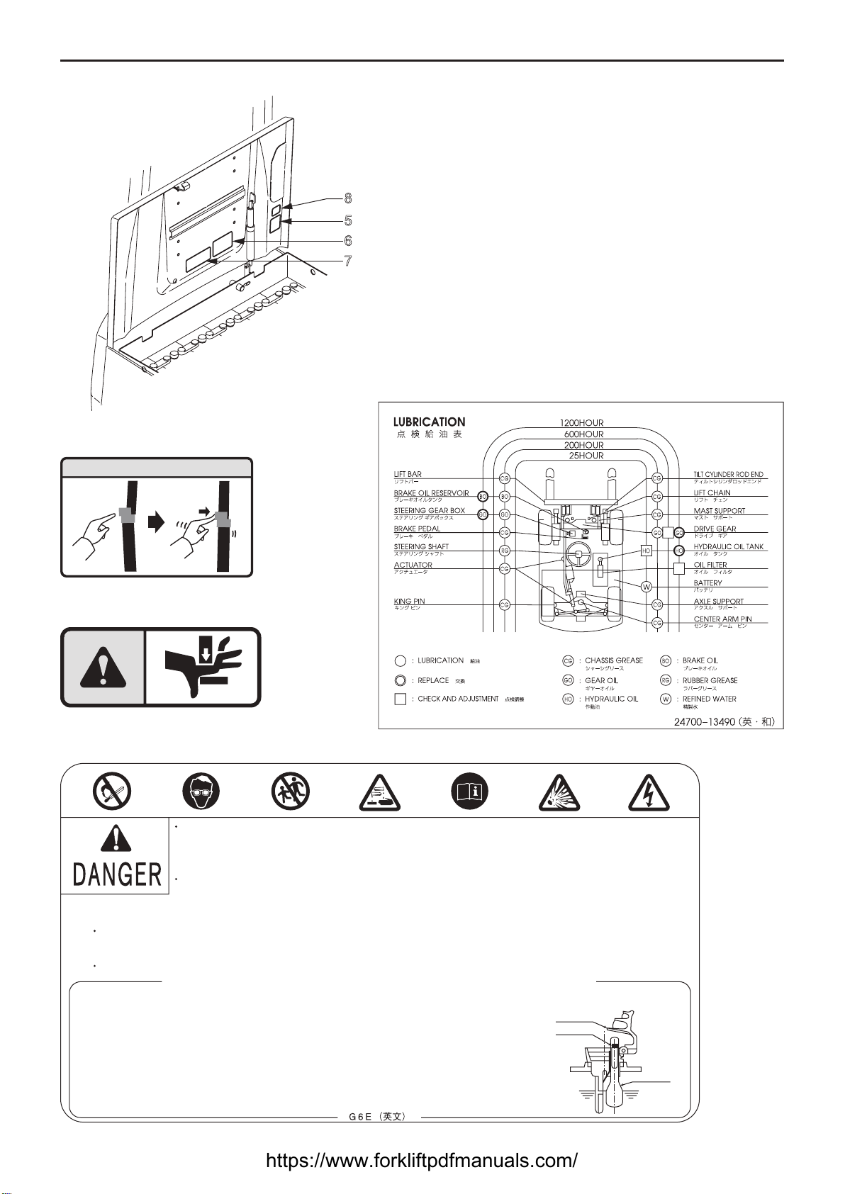
Safety labels2.
The illustration below shows the location of safety labels for safe operation.
Always protect the safety labels from contamination and damage.
If they are damaged or lost, replace with new ones.
1
10
12
11
29 3 410
221W074E
No. Parts No. Parts Name Q'ty Notes
1 50004-65160 Plate, caution 1 Safety operation
2 50004-65170 Plate, caution 1 Parking brake
3 50004-65050 Plate, caution 2 No person on / under for
4 50004-65060 Plate, warning 1 Shearing point
5 50004-65180 Plate, caution 1 Battery cover lock
6 24700-13490 Plate, lubrication 1 Lubrication
738540-00630 Label, caution 1 w / battery, SHINKOBE
38540-00520 w / battery, G6E
8 50004-65220 Plate, caution 1 Caution for fingers
90902-69954 Label, tyre 1 Air pressure (bar) FB10P-15P
0902-69964 Air pressure (bar) FB15P-28P
0902-69944 Air pressure (bar) FB30P
10 0902-69944 Label, tyre 1 Air pressure (bar) FB10P-18P
0902-69964 Air pressure (bar) FB20P-28P
0902-69914 Air pressure (bar) FB30P
11 50004-65190 Label, hook 3 Hook position
12 24700-04830 Plate, warning 1 In case of tipover
https://www.forkliftpdfmanuals.com/

6
1
PRECAUTIONS FOR SAFETY OPERATION
1
Do not overload. observe allowable load (blue zone).
2 Prior to operation, check performance of brake
or turn quickly.
3 Do not make a sudden start and brake or turn
quickly.
4 Do not make a sudden valve lever operation at a
high lift.
5 Do not run sideways or handle on an incline.
6 When the red lamp of battery capacity indicator
turns on, charge battery.
7
Check electrolyte every week and replenish water.
8 Be sure to use the prescribed fuses.
2
Apply parking brake before
leaving truck. Make adjust
to provide adequate braking.
3
50004-65050
WARNING
4
警告
WARNING
1
Name plate
(page 9)
221W0001
https://www.forkliftpdfmanuals.com/
7
7
GASES produced by this battery can be explosive.
Cigarettes, flames or sparks could cause battery to explode.
Make sure batteries are stored and charged in a wellÐventilayed area.
Batteries contain SULFURIC ACID can cause severe burns.
Avoid contact with skin, eyes or clothing.
In event of accident flush with water and call a physician immediately.
Wear rubber gloves to prevent ELECTRIC SHOCK during checking.
and maintaining.
Keep out of reach of children.
IMPORTANT POINT FOR MAINTENANCE
Keep the electrolyte level at proper height.
(When electrolyte decreased, fill purified water
and stop filling immediately if confirmed the white line of the
float as shown herein, for overÐfilling causes overflow.)
Always give the battery an adequate charge and
do not use the battery at overdischarged condition.
Keep the surface of battery clean and dry.
1.
2.
3.
(EX.) VENT PLUG
White line
Stopper
FLOAT
8
5
Lock release method of gas spring
5
8
6
7
(with Japnese
battery only)
221W0002 6
https://www.forkliftpdfmanuals.com/

8
11
50004-65190
12
WARNING
Fasten
Seatbelt
Do Not Jump ! Lean Forward
Hold
On
Tight
Brace
Feet
IN CASE OF TIPOVER
Lean
Away
From
Impact
Truck can
TIP OVER !
Risk of serious
INJURY
or DEATH
1.
2.
3.
Lateral tipover can occur when unloaded if the combination of speed
and sharpness of turn produces an overturning moment which exceeds
the stability of the truck.
Lateral tipover can occur if overloaded or loaded within capacity and the
load is elevated and if turning and/ or braking when traveling rearward
or if turning and/ or accelerating when traveling forward produces an
overturning moment which exceeds the stability of the truck.
Rearward tilt and/ or off-center positioning of the load and / or uneven
ground conditions will further aggravate the above conditions.
Longitudinal tipover can occur if overloaded or when loaded within capacity
and the load is elevated if forward tilt. braking in forward travel. or
commencing rearward travel produces an overturning moment which
exceeds the stability of the truck.
Serious injury or death can occur to the operator if he/ she is trapped
between the truck and the ground.
4.
The operator should stay with the truck if lateral or longitudinal tipover
occurs. The operator should hold on firmiy and lean away from the point
of impact.
The operator should stay with the truck if it falles off a loading dock or
ramp. There are other situations where the environment of the landing
area presents a severe hazard. In those incidents. it may be prudent for
the operator to leave the truck.
1.
2.
FOR SAFETY NOTICE FOLLOWING WARNINGS
24700-04830
IN CASE OF TIPOVER
9: for Front tyre (only for EEC)
FB10P / 14P FB15P ~ 28P FB30P
10: for Rear tyre (only for EEC)
FB10P ~18P FB20P ~ 28P FB30P
https://www.forkliftpdfmanuals.com/

9
Maximum lifting height [cm]
Mast type
Capacity code
Classification
of tyre
B : Large capacity battery
equipped
C : Stationary charger
D : Dust resistant
P : Pneumatic tyre
PN : No puncture tyre
PC : Cushion tyre
U : High speed type
NO CODE
:
Two stage full visibility (simplex) mast
M :
Three stage full free lift (triplex) mast
(Full visibility mast)
PFL : Full free lift (duplex) mast
(Full visibility mast)
CS : Cold storage use for -35°C
FCS : Cold storage use for -50°C
RP : Rust resistant
Z : Special type
Attachment etc.
FB 75
10 : 1000kg
14 : 1350kg
15 : 1500kg
18 : 1750kg
20 : 2000kg
25 : 2500kg
28 : 2750kg
30 : 3000kg
Model name and serial numbers3.
lName plate
Model name
MODEL
MAXIMUM
LOAD/LC
LIFT HEIGHT
SERIAL NO.
MFG.YEAR
VOLTAGE
SERVICE WEIGHT
W/O BATTERY
BATTERY WEIGHT
50006-95900
kg
kgMIN.
V
kgMAX.
mm
LOAD CHART
LIFT HEIGHT
LOAD CENTER mm
CAPACITY kg
kg /
kg /
mm
mm
mm
mm
MODEL
MAXIMUM
LOAD/LC
LIFT HEIGHT
SERIAL NO.
MFG.YEAR
VOLTAGE
SERVICE WEIGHT
W/O BATTERY
BATTERY WEIGHT
50006-91510
kg
kgMIN.
V
kgMAX.
mm
LOAD CHART
LIFT HEIGHT
LOAD CENTER mm
CAPACITY kg
kg /
kg /
mm
mm
mm
mm
(For Standard)
(For CE)
https://www.forkliftpdfmanuals.com/

10
Serial numbers
8
1
3
5
7
6
2
221W072E
MODEL
MAXIMUM
LOAD/LC
LIFT HEIGHT
SERIAL NO.
MFG.YEAR
VOLTAGE
SERVICE WEIGHT
W/O BATTERY
BATTERY WEIGHT
50006-95900
kg
kgMIN.
V
kgMAX.
mm
LOAD CHART
LIFT HEIGHT
LOAD CENTER mm
CAPACITY kg
kg /
kg /
mm
mm
mm
mm
lLocation of serial numbers
No. Serial numbers Stamped position
1 Serial No. of a truck Stamped on the name plate
2 Serial No. of a chassis Stamped on the right chassis
3 Serial No. of a mast Stamped on the mast name plate
4 Serial No. of a front axle Stamped on the gear case
5 Serial No. of a traction motor Stamped on the motor name plate
6 Serial No. of a hydraulic motor Stamped on the motor name plate
7 Serial No. of a EPS motor Stamped on the motor name plate
8 Serial No. of lift cylinders Stamped on lift cylinders
9 Serial No. of tilt cylinders Stamped on tilt cylinders
https://www.forkliftpdfmanuals.com/

11
152E101
Cautions for maintenance
4.
General precautions
152E102
152E103
152E104
lWhen replacing any parts, be sure to use genuine
NICHIYU parts.
lWhen parts are assembled, always replace old
packing and O-rings with new ones. In addition, be
sure to apply a light coat of grease on the O-rings and
oil seals before installing them.
lAs shown in the illustration, face the flat side of the
C-shape retainer in the direction the force is applied
when installed.
lAs shown in the illustration, face the slit side in the
direction the force is applied when driving in a spring
pin.
lThe split pin must be replaced with a new one and
split so it will not come out.
lWhen using a thrust washer with oil grooves cut,
observe the direction of installation.
lWhen connecting and disconnecting couplers of
electrical harnesses, always disconnect the battery
plug.
Retainer for a
groove Retainer for a
hole
Oil grooves
https://www.forkliftpdfmanuals.com/

12
Using liquid packing
Applying liquid packing
l
152E105
152E106
152E107
Scraper
Liquid packing
3 -3.5 mm
Good
Apply liquid packing
Within 15 minutes
Wait for 30 minutes or more
Assembly
Filling oil/Operation
Not Good
Key to evacuate
liquid packing
3 - 3.5 mm
Mating surface
Cut the nozzle at the
second section
Remove the sealer adhered on the mating surface of the
casing by using a scraper or equivalent tool. Be careful
not to make scratches of 0.3 mm or deeper. If scratches
are made, repair the area by using an oil stone.
Wipe off the mating surfaces using a cloth soaked in
gasoline to remove oil and contamination.
* Do not use kerosene, light oil, or crude oil.
1.
Cut the nozzle of the liquid packing tube at about the
second section so that the bead width will be 3 to 3.5
mm.
2.
Attach a key for rolling up the tube, and apply the liquid
packing to the mating surface while rolling up the tube.
* Do not smooth out the bead; doing so may cause
leakage.
* When applying the liquid packing to bolt holes, apply it
on the internal portion of the mating surface.
3.
Close the mating surfaces within 15 minutes after the
liquid packing is applied.
4.
When tightening the bolts, always tighten temporarily
first, and then tighten them gradually, moving from one to
the next in a diagonal pattern.
5.
Wait for more than 30 minutes before adding oil or
operating the machine.
* Failure to do so may cause oil leakage.
6.
Scraping before application of seal
l
https://www.forkliftpdfmanuals.com/

13
152E108
Deterioration of liquid packing
l
Once the tube has been opened, the liquid packing
anchoring the tip part of the nozzle might be cured and
deteriorated. Squeeze out that portion and discard it
before reusing the packing.
1.
If oil (filler) was separated from the liquid packing and
the packing appears shiny when it is squeezed out, this
indicates that the liquid packing has deteriorated.
* Although the oil may have been separated from a
liquid packing opened before its expiration date, this is
not an indication of deterioration.
2.
* If the oil has separated, the
packing has deteriorated.
Squeeze out the
bead about 20
mm and check.
CAUTION
If the state of the packing is normal, it will be
cured within approximately 2 hours. However, a
deteriorated packing will not.
https://www.forkliftpdfmanuals.com/
This manual suits for next models
7
Table of contents
Popular Forklift manuals by other brands

Presto Lifts
Presto Lifts Power Stak PPS2200-62NAS Installation, operation and service manual

Doosan
Doosan D110S-5 with OCDB Disassembly/Assembly

TMG
TMG TMG-PJ45S product manual

Jungheinrich
Jungheinrich ERE 224 operating instructions

Still
Still RX60-60 Original instructions

Crown
Crown Pallet Truck PC 4500 Series Operator's manual


