TMG TMG-PJ45S User manual

4500-lb Pallet Jack Scale Truck
Model:TMG-PJ45S
PRODUCT MANUAL
Please read the product manual completely before assembly
Check against the parts list to make sure all parts are received
Wear proper safety goggles or other protective gears while in assembly
Missing parts or questions on assembly?
Please call: 1-877-761-2819 or email: cs@tmgindustrial.com
Do not return the product to dealer, they are not equipped to handle your requests
WWW.TMGINDUSTRIAL.COM Toll Free:1-877-761-2819

CONTENT
1. Instruction manual..............................................................................................3
1.1 Range of application........................................................................... ........3
1.2 Operational order........................................................................................3
1.3 Safety precautions.......................................................................................3
2. Product Description............................................................................................4
2.1 Brief Introduction.........................................................................................4
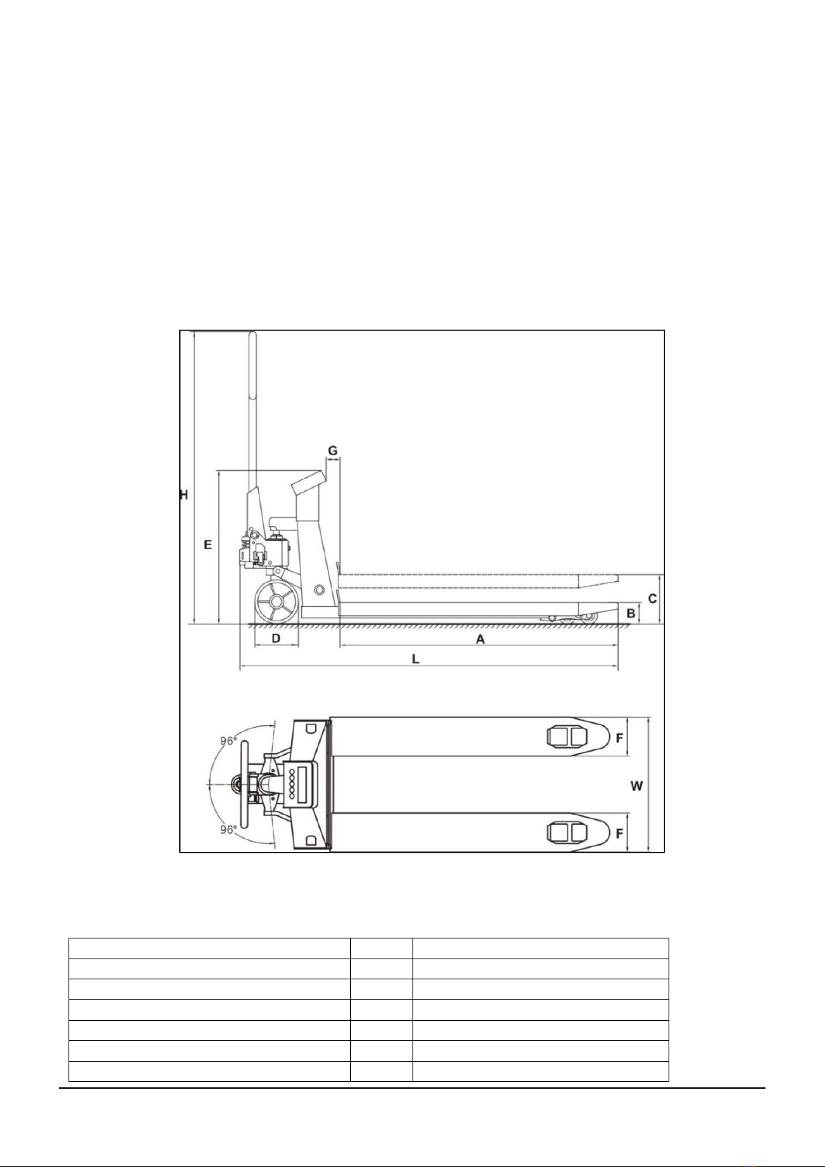
2.2 Technical data.............................................................................................4
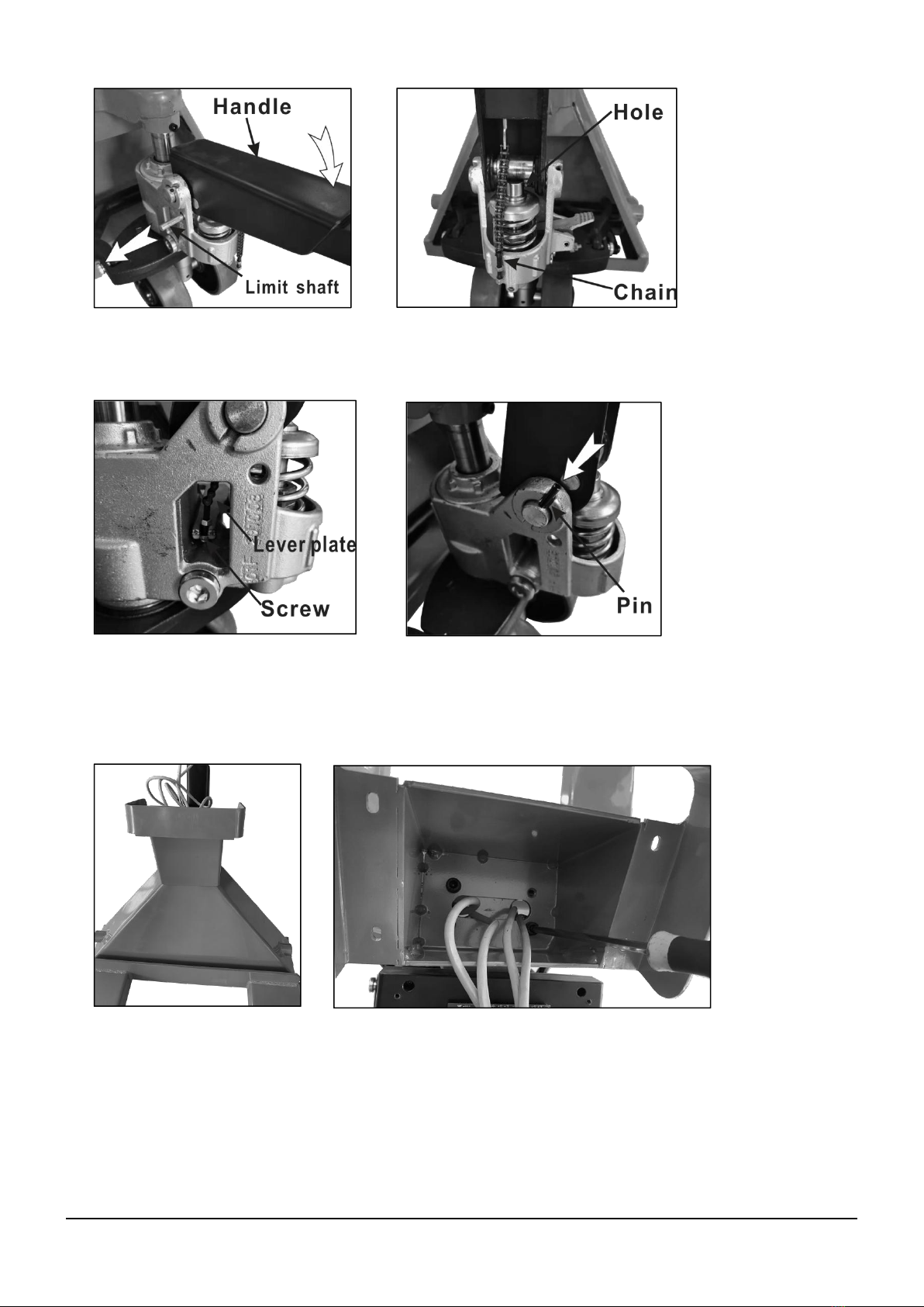
2.3 Diagram of Assembly..................................................................................5
3. Operating instruction...........................................................................................7
3.1Test run.........................................................................................................7
3.2 Adjustment of control handle knob.............................................................8
3.3Safety shutdown...........................................................................................8
4. Display instruction...............................................................................................8
4.1 Technical data of display.............................................................................8
4.2 Display area introduction.............................................................................9
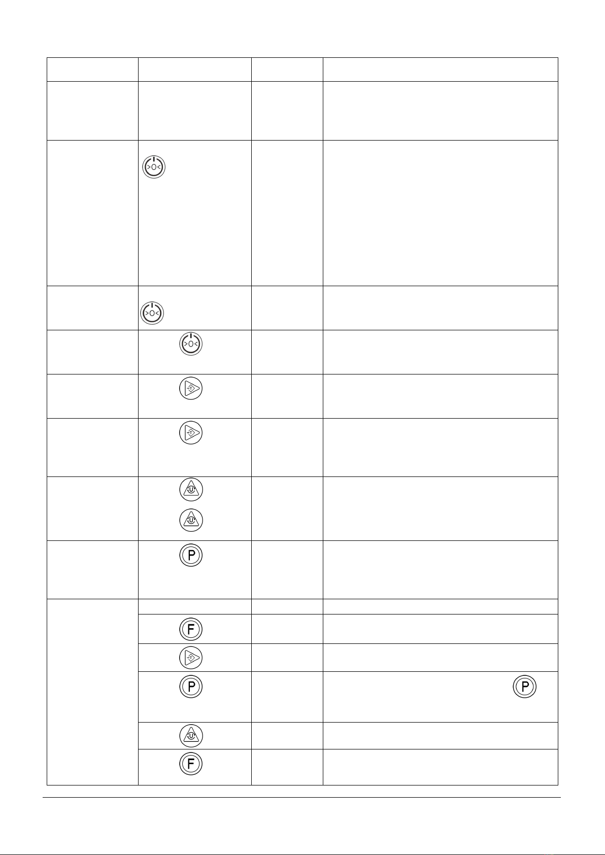
4.3 Button Function Introduction.......................................................................9
4.4 Calibration Introduction.............................................................................10
4.5 Recharging Power.....................................................................................11
4.6 Warning......................................................................................................11
5. Trouble shooting................................................................................................12
6. Routine Maintenance and Cleaning..................................................................13
7. Exploded Drawings and Parts List....................................................................15

WWW.TMGINDUSTRIAL.COM P0318 Toll Free:1-877-761-2819
1. Instruction manual
1.1 Range of application
Please use and maintain the scale pallet truck according to this instruction manual.
Operations that are not listed in this manual may cause harm to the operator or the
scale pallet truck, and may cause property damage. Please read the name plate before
use, and make sure that the load isn’t overweight. Please avoid unbalance load.
Flammable, explosive, and humid environment may cause explode or short circuit of
display.
1.2 Operational order
The scale pallet truck should be operated by well trained person, who knows how to do
loading, is clear about contents in this instruction manual, and masters operating skills.
All users should read and understand contents of this instruction manual. The
manufacture will not be liable for any damage resulting from failure to comply with this
instruction manual.
1.3 Safety precautions
1) Never lift a heavy load with just the points of the forks. This could damage the
electronic weighing elements permanently.
2) Never weigh without a pallet. This could affect the accuracy of the weighing result.
3) Use caution in the vicinity of moving parts—these parts can cut and/or crush hands,
arms, feet, and legs.
4) Always center the load you are lifting on both forks.
5) Do not operate the weighing system while others are on or near the unit.
6) It is the sole responsibility of the purchaser to train their own employees in the
proper use and maintenance of this equipment.
7) Do not use the weighing system in potentially explosive areas.
8) Do not carry passengers with the truck.
9) Do not lift unstable loads.
10) Check the accuracy of the scale on a regular basis to prevent faulty readings.
WWW.TMGINDUSTRIAL.COM P02/18 Toll Free:1-877-761-2819

WWW.TMGINDUSTRIAL.COM P04/18 Toll Free:1-877-761-2819
2. Product Description
2.1 Brief Introduction
Scale pallet truck combines small manual pallet truck and weighing system, which is
composed of high precision weighing sensor and digital display. Scale pallet truck can achieve
carrying and weighing simultaneously, and each weighing data can be displayed automatically.
It has advantages of smaller size, easy moving, convenient lifting/lowering, flexible steering,
and accurate measurement.
2.2 Technical data
Technical data of scale pallet truck (hardware):
Item/Model
Unit
TMG-PJ45S
Rated Load
lbs
4500
Overall Length L
In.
64
Overall Height H
In.
47-1/4
Fork Length A
In.
44
Fork Lowest Height B
In.
3-1/8
Fork Highest Height C
In.
7-1/2

WWW.TMGINDUSTRIAL.COM P05/18 Toll Free:1-877-761-2819
Indicator Clearance G
In.
2-1/2
Height to Top of Indicator E
In.
26-1/2
Overall Width W
In.
27
Fork Width F
In.
6-1/4
Diameter of Carrying Wheel
In.
2-3/4
Diameter of Steering Wheel D
In.
7
Weight
KG
99
Input voltage
AC100~240V(+10%, -15%)-
50~60HZ
2.3 Diagram of Assembly
Scale pallet truck is composed of fork assembly, frame assembly, display assembly, pump
assembly, and control handle assembly.
Figure 1: Structure of Scale Pallet Truck
1) Installation of pump handle
A. Make sure the lever is pushed down to the “pump” position.
B. Place the handle on the middle of the pump, and thread the fixed shaft through the hole
in the pump and handle.

WWW.TMGINDUSTRIAL.COM P06/18 Toll Free:1-877-761-2819
C. Press the handle to the lowest position, and remove the limit shaft.
D. Thread the chain through the hole in the fixed shaft.
E. Insert the screw into the lever plate.
F. Knock the pin into the hole in the fixed shaft.
2) Installation of display
Fix the supporting structure on the frame with screws.

WWW.TMGINDUSTRIAL.COM P07/18 Toll Free:1-877-761-2819
A) Fix the circuit board on the back of display with screws, and then fix the wires of sensor
to the circuit board according to the table.
B) install the display into the rack, and fix with screws. Please be cautious of the wire
harness.
3. Operating instruction
3.1 Test run
Test run is only allowed at safe area, and only staff present. The load’s center of gravity should
between the forks. Please don’t put the load at the end of forks. Evenly distributed weight can
maximum carrying capacity.
Wire of Sensor
Symbol of Socket
Red
E+
Black
E-
Green
S+
White
S-

WWW.TMGINDUSTRIAL.COM P08/18 Toll Free:1-877-761-2819
3.2 Adjustment of control handle knob
The control handle switch has three positions. Press down the handle switch to lower position,
then pump the handle up and down to lift load. When keeping the switch at the neutral position,
the forks will not be able to lift. When pulling the pallet truck, the switch should be kept at
neutral position. Forks will lower down when lift the switch to upper position. When release the
switch, it will goes back to neutral position automatically. Please make sure the forks are totally
under the load before lifting.
3.3 Safety shutdown
Please don’t park on the slope. Forks should be at lowest position when parking, and wheels
should be fixed after parking. Fence should be used to protect the truck while transfer.
4. Display instruction
4.1 Technical data of display:
Standard
GB/T 7724-2008
Accuracy Class
Grade 3
Input Sensitivity
≥1.5 uV/e
Power
7.4V/4000mAh Lithium cell
Operating Temperature
0℃~40℃,Humidity 10%~85% (RH)
Storage Temperature
-20℃~60℃,Humidity 10%~95%
(RH)
Lowering
Neutral
Lifting

WWW.TMGINDUSTRIAL.COM P09/18 Toll Free:1-877-761-2819
4.2 Display area introduction
1. Null point 2. Low power 3. Tare 4. Counting mode 5. Lb6.Kg
4.3 Button Function Introduction
Turn on and off button/zero-setting button
This button is used for power on and off.
It is also used for zero-setting if value is in the range of zero-setting.
Tare button/right shift button
This button is used for taring except negative value when turn on or over the max.
weight.
It is right shit button during the function setting and calibration operation.
Unit button/ load button
This button is unit conversion button, which can be used to convert kg and lb.
It is used as load button during function setting operation and calibration
operation.
Function button
This button is use for function setting such as count, lock and accumulative total
Print button/enter button
This button is used for print when the printer is connected.
During function setting operation and calibration operation, it is used for
confirmation.

WWW.TMGINDUSTRIAL.COM P10/18 Toll Free:1-877-761-2819
Operation
Display
Remark
1 Charge
Plug in external
power supply
[CHArGE]
[---]
[PbtXX]
[-End-]
Charging
Charging, scroll display from right to left
Showing the charging capacity
End of charge
2 Boot
Press and hold
for 1 second
[-t 15-]
[UEr2.01]
[17.09.03]
[09.38]
[Pbt 85]
[8. 8. 8.]
[0.0]
Appearance Model
Software Version Number
Date(year.month.day), set showing with
the clock
Time(hour.second), set showing with the
clock
Appearance battery power is 85%
Appearance self-check, scroll display
from right to left
Weighting status
3 Shutdown
Press and hold
for 2 seconds
[Pbt 80]
[OFF]
Appearance battery power is 80%
Cut off the power supply
4 Zero Setting
Press
[ xx.x]
[ 0.0]
Weight is less than the zero setting
range IO%FS, and stable
Zero setting, [Zero] light on.
5 Without Tare
Press
[positive
value]
[0.0]
Weight is large than zero and stable.
[Without tare] light on, showing the net
weight. It can be repeated.
6 Clear
Press
[display
negative
value]
[Without tare]light on or Zero light on.
Clear the package weight, the light off.
7 Unit
Conversion
Press
Press
[xx.x]
[yy-y]
“Pound” shows, [lb] light on (Permit
swift)
“kg” shows, [kg] light on.
8 Print
Press
[xxa]
Weight is larger than minimum weight,
and the weight is stable. Weigh should
return to zero before next weighing.
(<20d)
9 Sample
count
Weigh return to zero before counting.
Press
[PCS 10]
Enter sample count mode.
Press
Choose sample 10, 20, 50, 100
Press
Put sample on truck, then press to
confirm. Count showed on screen, and
[PCS] light is on.
Press
Check unit weight and total weight.
Press four
times
Back to weighing model, and [PCS] light
is off

WWW.TMGINDUSTRIAL.COM P11/18 Toll Free:1-877-761-2819
10 Lock
Press two
times
[Hold]
Enter weigh lock mode.
Press
Enter lock mode. When weight is stable,
the weigh is locked.
Press
[0]
Exit weigh lock mode, and back to weigh
mode.
Press one
times
Enter accumulate function.
11
Accumulate
Press three
times
[ACC 12]
Choose 1 or 2. The selected one will
flash.
Press
[ACC 12]
1. Manually accumulate 2.
Automatically accumulate
Press
Enter accumulate mode.
Press
Shows cumulative number, 2 seconds
later shows accumulative weight, 2
seconds later back to accumulate mode.
Press
Under selected mode 1, press to
print out cumulative number after weight
is stable.
Under selected mode 2, cumulative
number will be printed out automatically
after weight is stable.
Cumulative number will be cleared
automatically after shut down.
Back to weighing mode.
4.4 Calibration Introduction
Calibration method:
Turn on the power, then press the before zero-setting to enter the calibration interface.
Step
Operation
Display
Note
1
[xxxxxx]
Display A/D value, and check if the sensors are
working.
2
Press
[CAL 00]
Start zero correction, and confirm no-load. Press
when machine is stable.
3
Press
[-------]
Zero correction
4
A few seconds
later
[1500.0]
Display the max. weight value for 2 seconds
5
2 seconds later
[-LoAd-]
Loaded weight
6
Press
[100.0]
Input loaded weight value

WWW.TMGINDUSTRIAL.COM P12/18 Toll Free:1-877-761-2819
7
Press
[-------]
Range correction
8
A few seconds
later
[100.0]
Display the loaded weight value, and enter the
weighing mode
Note: 1 if zero is constant, only the range correction is made. When [CAL 00] is displayed,
press the to skip zero correction, and enter the range correction. (compensation
calibration)
2 if only the zero correction is made, please press , when [-LoAd-] is displayed. Input
[ 0.0], and press to back to the normal weighing interface.
4.5 Recharging Power
1. AC power: 100~240V/ 50~60Hz
2. Plug the round end of the charger into the port on the back of the display and then plug into
the AC power supply. Reverse operation after full charge.
WARNING: If the machine is not used for more than 6 months, it must be charged every 6
months to reduce the battery life
4.6 Warning
1. It is strictly prohibited to put the scale on high temperature or humid place.
2. Do not let cockroach and organisms living in the machine.
3. Striking and overload is strictly prohibited.
4. If you have any suggestions, please feel free to contact us.

WWW.TMGINDUSTRIAL.COM P13/18 Toll Free:1-877-761-2819
5. Trouble shooting
Fault Description
Reason
Method
Fork cannot reach the
wanted height
Lacking of hydraulic oil.
Add hydraulic oil.
Fork cannot descend
1.Hydraulic oil is not pure.
1.Change hydraulic oil.
2. Air in the hydraulic oil.
2. Bob up and down the handle to extract
the air.
3. The fork has been kept in
high position for a long time,
and the large piston is
rusted.
3. Keep the fork in the minimum height
when work is done. Pay attention to
lubricate the piston lever.
4. The adjustment nut or the
adjustment screw is in an
incorrect position.
4. Readjust the position of the adjustment
nut or the adjustment screw.
Oil leak
1. Seal ring is burn-in.
1. Change seal ring.
2.The cylinder is cracked.
2. Change cylinder
Forks descend without
operation
1. Some of the hydraulic
system elements are
damaged or crazed.
1.Check and change the damaged
elements.
2.The adjustment nut or the
adjustment screw is in an
incorrect position.
2. Readjust the position of the adjustment
nut or the adjustment screw.
Malfunction of Display
1. There is no value
displayed on the indicator.
1.Check whether the power line is well
connected.
2.The key switch does not
work.
2. Check whether the power line is well
connected or change the key switch.

WWW.TMGINDUSTRIAL.COM P14/18 Toll Free:1-877-761-2819
6. Routine Maintenance and Cleaning
The daily inspection and maintenance of scale pallet truck can improve the service time of the
vehicle.
1) Check whether the pump is dripping.
2) Check whether there are sundries entangled in the wheels or axle.
3) Lubricate the moving parts of the pallet truck once a day.
4) Check whether the weighing display is well.
5) Do not place the vehicle in a intense direct sunlight area for a long time, otherwise, it
may damage the display.
6) The battery should be charged in time when the power is low. Otherwise, it may
short the service life of the battery.
7) Wipe the scale assembly with a damp cloth using water only.
8) Do not spray cleaners onto scale indicator.
9) Do not wash-down the vehicle with a pressure cleaner or water hose.
10) Do not allow water or liquids to drip on the scale indicator.

WWW.TMGINDUSTRIAL.COM P15/18 Toll Free:1-877-761-2819
7. Exploded Drawings and Parts List
Main exploded drawings
No.
DESCRIPTION
Q’TY
No.
DESCRIPTION
Q’TY
1
Handle assembly
1
12
Spherical composite washer
4
2
Pump assembly
1
13
Fork connection pin
4
3
Thrust plate pin
2
14
Spring washerφ12
8
4
Swing arm
1
15
Screw M12X30
8
5
Frame assembly
1
16
Fork
1
6
Shaft ringφ16
4
17
Weighing sensor
4
7
Pushing rod and load wheel
assembly
2
18
Tapping screw 3X10
4
8
Screw M8X35
4
19
Supporting structure
1
9
Pushing rod pin
2
20
Screw M8X16
4
10
Transmission assembly
2
21
Display
1
11
shaft
2
22
Long shaft
1

WWW.TMGINDUSTRIAL.COM P16/18 Toll Free:1-877-761-2819
Structure of Control Handle Assembly
Pump assembly
No.
DESCRIPTION
Q’TY
101
Handlebar
1
102
Spring pin
2
103
Handle
1
104
Limit board
1
105
Torsional spring
1
106
Lever
1
107
Connecting rod
1
108
Chain lever
1
109
Handle triangle
2
110
Pinch roller
1
111
Roller pin
1
112
Spring pin
2
113
Fixed pin
1
114
Subplate
2

WWW.TMGINDUSTRIAL.COM P17/18 Toll Free:1-877-761-2819
No.
DESCRIPTION
Q’TY
No.
DESCRIPTION
Q’TY
201
Pump core
1
225
Compound gasket Φ10
1
202
Spring cap
1
226
Adjusting screw
1
203
Spring
1
227
Safety valve spring
1
204
Scraper seal
1
228
Steel ball pad
1
205
Seal ring
1
229
Gasket
1
206
Steel ball
1
230
Firing pin
1
207
Compound gasket
1
231
Firing pin seat
1
208
Screw-plug
1
232
Compound gasket
1
209
Volute spring
1
233
O ring
2
210
Valve core
1
234
Firing pin spring
1
211
Valve body
1
235
Nut
1
212
Pump body
1
236
Screw
1
213
Spring pin
1
237
Spring pin
1
214
Bearing
1
238
Lever plate
1
215
Spring pin
2
239
Screw
1
216
Thrust plate
1
240
Compound gasket
1
217
Shaft ring
1
241
Seal ring
1
218
Steering wheel shaft
1
242
O ring
1
219
Bearing
2
243
Pump cap
1
220
Steering wheel
2
244
O ring
1
221
Shaft ring
2
245
Scraper seal
1
222
Dust cover
2
246
Piston rod
1
223
Gasket
2
247
Steel ball
1
224
Adjusting screw
1
Transmission assembly
No.
DESCRIPTION
Q’TY
No.
DESCRIPTION
Q’TY
301
Joint
1
308
Load wheel
2
302
Nut M18
1
309
Bearing
4
303
Pushing rod bolt
1
310
Spring pin φ5X30
4
304
Shaft ring φ16
1
311
Load wheel pin
2
305
Pushing rod
1
312
Pushing rod connection pin
1
306
Frame of roller
1
313
Spring pinφ5X25
1
307
Linking plate
2

WWW.TMGINDUSTRIAL.COM P18/18 Toll Free:1-877-761-2819
Display assembly
No.
DESCRIPTION
Q’TY
401
Operation panel
1
402
Upper cover
1
403
Mainboard of display
1
404
Tapping screw 3X8
4
405
Tapping screw 3X10
2
406
Battery holder
1
407
Pedestal
1
408
Battery
1
409
Tapping screw 3.5X10
4
410
Sensor connection circuit
board
1
411
Tapping screw 3X6.5
3
Table of contents
Other TMG Forklift manuals