Nippon DENON DR-M20 User manual

Hi-Fi
Component
CK
STEREO
CASSETTE
TAPE
DE

|
TABLE
OF
CONTENTS
FEATURES
.......5-::
fy
ted
date
deeievacn
dteats41d
gIB
oe
tease
PES
EE
oe
nota
SBECIPICATIONS
inci
np
ie
cin
ptealeiesaa
cod
wenb
is
samvdensn
aaah
“BLOCK
DIAGRAMLcs
o<tt0
LOM
aseed
eevee
aoe
eha
etenak
Bde
eee
EVEL
DING
RAM
Gicaeut
ora
de
cunsd
tan
soucei
tastes
mites
eines
ea
PART
NAMES
AND
FUNCTIONS
........ccsccecceescceececeseveueses
OUTLINE
OF
THE
MECHANISM
CONTROL
MICROCOMPUTER........
rhe
raals
lactate
estat
ane
este
eal
nace
a
DISASSEMBLY
INSTRUCTIONS
|
ocxakit
ob
oacteseaituredesiwasaad
ets
ADJUSTING
AND
CHECKING
THE
MECHANISM
SECTION
inci
catdiatvcat
teens
edeeaawiad
exo
eeae
es
ADJUSTING
THE
ELECTRICAL
SECTION
2...
0...
cece
eee
e
cence
teen
eeees
PARTS
iST
OPP
WsBOARD:
fi
aryccPeed
gous
sx
tee
tedinns
Gate
weaes
PARTS
LIST
OF
EXPLODED
VIEW
......
cc
cece
cee
c
cece
cece
enenenenees
EXPLODED
VIEW
OF
CABINET
AND
CHASSIS
GROUP............2.0005-
EXPLODED
VIEW
OF
MECHANISM
VM860
UNIT
..........000
cee
eee
eens
PARTS
LIST
OF
MECHANISM
VM860
UNIT
AND
OTHER
PAR
TS
¥.cosneal
eee
nessa
tenes
Bae
oad
wae
aecen'
SCHEMATIC
DIAGRAM
OF
AUDIO
AMP
UNIT
.........0.00c
cece
eee
e
ees
P.W.
BOARD
OF
KU-5880
AUDIO
AMP
UNIT
.........
cee
cee
c
cece
neces
SCHEMATIC
DIAGRAM
OF
POWER/LOGIC
UNIT........0.0000
eee
eee
ee
P.W.
BOARD
OF
KU-5870
POWER/LOGIC
UNIT
AND
KU-5890
MECHANISM
UNIT
.....60
4000
h005
cueeeeeawcaesanaaes
SCHEMATIC
DIAGRAM
OF
COUNTER
METER
UNIT.......
00.000
eee
eee
SEMICONDUCTORS
as'sctaautasan
toca
eee
eeghardwawhte
eee
teed
WIRING
DIAGRAM.
casi
tues,
times
ontye
arson
wnat
eseaetendeeas
FEATURES
(2)
=
Computer-controlled
servo
technology
*
Closed-loop
dual-capstan
tape
transport.
*
Silent,
soft-touch
controls
provide
maximum
ease-of-use.
-
Computer-controlled,
full-logic
tape
controls
enable
fool-proof
operation.
s
Three-head
design
utilizes
DENON’s
new
SF
record/playback
combination
head
assembly.
=
Computing
tape
counter
with
4-digit
readout
and
memory
stop.
s
Dolby-C
noise
reduction
systems
(Double
Dolby
System).
as
Extended
range,
dual-color
fluorescent
peak
meters.
=
Auto
tape
selector.
s
Recording
Bias
adjustment.
23
24
25
26
27
28
29
30

SPECIFICATIONS
OTYPE
Shido
se
aoa
ee
a
peas
Vertical
tape
loading
4-track
2-channel
stereo
cassette
tape
deck
eHeads
.
1...
ee
eee
ee
eet
SF
Record/Playback
combination
head
x
1
Erase
head
(Ferrite)
x
1
eMotors
....-
0-2
e
seen
eee
Electronic
servo
DC
motor
(for
capstan)
x
1
DC
motor
(for
reel
winding)
x
1
eTape
Speed
.............
4.8
cm/sec.
e
Fast
forward,
rewind
time
...
Approx.
90
sec.
with
a
C-60
cassette
e
Recording
bias
...........
105
kHz
e
Overall
S/N
ratio
.........
Dolby
C
NR
on...
more
than
73
dB
(CCIR/ARM)
(at
3%
THD
level)
e
Overall
fequency
response.
...
25
~
19,000
Hz
+3dB
(at
~20
dB
METAL
tape)
eChannel
separation
........
More
than
40
dB
(at
1
kHz)
eCrosstalk...
2...
-
eee
ee
eee
More
than
65
dB
{at
1
kHz)
eWow
&
flutter
...........
0.045%
wrms
(JIS
method)
e
Inputs
WTO
Bean
he
Wee
orang
Gi
etane,
eRe
100mV
(—18
dB)
input
level
at
maximum
Input
impedance:
50
kohm
unbalanced
e
Outputs
ING.
epee
ee
ew
775mV
(0
dB)
output
level
at
maximum
(with
47
kohm
load,
recorded
level
of
200
pwb/mm)
Headphone
...........
1,.2mW
output
level
at
maximum
(optimum
load
impedance
8
ohm
~
1.2
kohm)
eAccessories
...
+--+
eee
eee
Parallel
pin
cord
x
2
@Power
supply
......-...-6-
50
Hz/60
Hz
compatible,
voltage
is
shown
on
rating
label
ePower
consumption
.......
18W
eDimensions
.........+00
434
(W)
x
115
(H)
x
286
(D)
mm
e@eWeight
...-
2.
ee
eee
eee
5.6
kg
=
Above
specifications
and
design
styling
are
subject
to
change
for
improvement.
™Dolby
noise
reduction
manufactured
under
license
from
Dolby
Laboratories
Licensing
Corporation.
“Dolby”
and
the
double-D
symbol
are
trademarks
of
Dolby
Laboratories
Licensing
Corporation.
WARNING:
1.
Component
parts
Parts
marked
with
Z\
and/or
shading
in
this
service
manual
have
special
characteristics
important
to
safety.
Besure
to
use
the
specified
parts
for
replacement.
2.
Leakage
current
Before
returning
the
appliance
to
customer,
test
the
leakage
current
when
the
power
plug
is
connected.
Use
a
calibrated
(with
an
error
of
not
more
than
5%)
leakage
current
tester
and
measure
the
leakage
current
from
any
exposed
metal
to
the
earth
ground.
Reverse
the
power
plug
polarity
and
test
the
above
again.
Any
current
measured
MUST
NOT
EXCEED
0.5
milliamps.
Corrective
measure
must
be
taken
if it
exceeds
the
limit.
{3)
SNId
SvVIa
YOLOITES
3dVi
OLNV
LINDUIS
/
980
ia
7JOYLNOD
svia
vost
L9373S
adVL
7
pOCUA
RRO
5
19078
YAGOONS
aA
TaN
GV3H
934
Ss990V3L
ie
dVul
Svid
Prrepeet
Z01LY
fee
cOeUA
|
NIV
O3Y
3ONV
Iva
ial
HO-1_
LNO
3NIT
L19373S
st0z1/02
39ynNos
SLAW
3NIT
M9018
¥300930
S3NOHd
tloer
9
{-lOLUA
YOLINOW
3dV
dWV
SNOHdOV3H
YA
LNdLNd
t
s990v3L
-
e
&
>
HO-7
HOLIMS
10101
Bz
\
:
b
1a1Ly
dN
UN
A100
NIV]
Gd
dNVO3ad
dV3H
ad
|
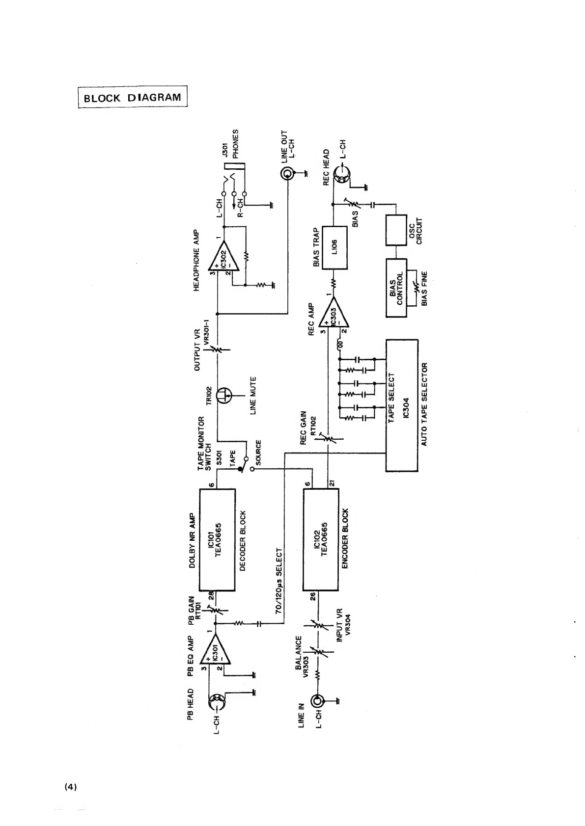
BLOCK
DIAGRAM
(4)

LEVEL
DIAGRAM
PLAYBACK
SYSTEM
TCcC-BO
(400Hz)
DOLBY
B-Type
200mWb/m
Lamv
(et
82)
PB
HEAD
PBEQ
AMP
PBGAINN
DOLBY
NR
AMP
(DECOOER)
OUT PUT
VR
HEADPHONE
AMP
TRIO2
|
po
32)
m
28
6
cTR202)
305)
!
PRONES:
LY
P
216)
rare)
OD
2s
me
en)
RTIO1
.
VR301
:
(RT2ZOn)
source
LINE
TAPE
MUTE
$301
(68)
(©)
LINE
out
é
CG)
@
©
@)
©)
©)
@)
ose
dB
dB
6
LINE
OUT
7
Gag
PHONES
OUT
1848
-20
2408
-30
-40
-50
60
-7008
-70
Od8=0.775V
RECORDING
SYSTEM
INPUT
FREQUENCY
400Hz
DOLBY
NR
SYSTEM
LINE
{ENCODER}
SOURCE
rr
BALANCE
VR
INPUT
VR
REC
AMP
BAND
TRAP
FILTER
REC
HEAD
L-106
(L-206)
TAPE
SELECTOR
TAPE
(dB)
70.808
(METAL)
~2.8dB
(CHROME)
-5.5dB
(NORMAL)
0dB=0.775V
(5)

(6)
|
PART
NAMES
AND
FUNCTIONS
|
®
®
DENON
orccision
aur
recimanpc¥/S
TEREO
CASSETTE
DECx
DA-w20
©@
©
®@
®
©
eS")
]
@
1.
POWER
switch
Controls
the
supply
of
AC
power
to
the
deck.
One
push
turns
the
deck
on,
a
second
push
turns
it
off.
The
deck
remains
in
a
stand-by
(non-operative)
mode
for
approxi-
mately
4
seconds
after
it
is
switched
on.
2.
EJECT
button
Press
this
button
to
eject
the
cassette.
When
the
deck
is
operating
(tape
is
running),
press
the
stop
(
®)
key
first
to
stop
the
tape
transport;
then
press
the
EJECT
button.
3.
COUNTER
RESET
button
Operation
of
the
button
resets
the
counter
to
all
zero.
4.
MEMORY
STOP
button
During
rewinding
operations,
the
tape
will
stop
at
the
“9000”
counter
point
automatically
when
this
button
is
pressed
in.
5.
DOLBY
NR
switches
The
left
Dolby
NR
switch
activates
(in)
or
deactivates
(out)
the
deck’s
Dolby
noise
reduction
circuitry.
The
right
switch
selects
between
Dolby
B-Type
(out)
or
C-Type
NR
(in).
6.
MPX
FILTER
switch
The
MPX
FILTER
switch
should
be
used
to
prevent
inter-
ference
with
the
Dolby
NR
circuit
when
making
Dolby
NR
encoded
recordings
of
FM
stereo
programs.
When
making
Dolby
NR
encoded
recordings
from
any
program
source
other
than
FM
stereo,
leave
this
switch
in
the
“off”
(out)
position.
G@@G@OG
©
D
OOP
BIAS.FIME
BALANCE
@
7.
MONITOR
switch
The
SOURCE
(in)
position
of
this
switch
allows
you
to
monitor
the
source
program
before
it is
recorded.
The
TAPE
(out)
position
of
this
switch
is
used
for
tape
play-
back
monitoring
or
simultaneous
monitoring
during
record-
ing.
8.
BIAS
FINE
ADJ
control
(for
NORMAL
and
CrO,
tape)
Adjust
the
bias
according
to
the
tape
characteristics.
Standard
biasing
is
obtained
at
the
center
click-stop
posi-
tion.
9.
BALANCE
controls
This
is
the
Knob
to
adjust
the
recording
level
balance
be-
tween
the
left
and
right
channels.
Turn
it
counterclock-
wise
to
reduce
the
right
channel’s
level
and
clockwise
to
reduce
the
left
channel's.
Usually,
put
the
knob
at
the
center
click
position.
10.
PHONES
jack
For
private
music
enjoyment
without
disturbing
others,
or
for
monitoring
a
recording,
a
set
of
headphones
may
be
plugged
in.
Impedance
should
be
from
8
to
1200
ohms.
11.
OUTPUT
LEVEL
control
This
control
adjusts
playback,
recording
monitor,
and
headphones
output
levels
for
the
both
channels
simultane-
ously.
12.
INPUT
LEVEL
controls
The
recording
input
level
is
adjusted
by
this
knob.
The
levels
in
the
left
and
right
channels
can
be
changed
sim-
ultaneously.
13.
Cassette
compartment
cover
When
a
cassette
tape
is
inserted
and
the
door
is
closed,
the
tape
is
automatically
wound
up
for
about
0.3
sec
to
eliminate
the
slack.
14.
TAPE
COUNTER
A
four-digit
readout
indicates
the
present
tape
count
posi-
tion.
15.
FLUORESCENT
PEAK
METERS
These
meters
indicate
recording
or
playback
peak
levels
for
each
channel.
16.
MEMORY
indicator
When
the
memory
switch
is
turned
on,
the
letters
of
“MEMO”
will
be
displayed.
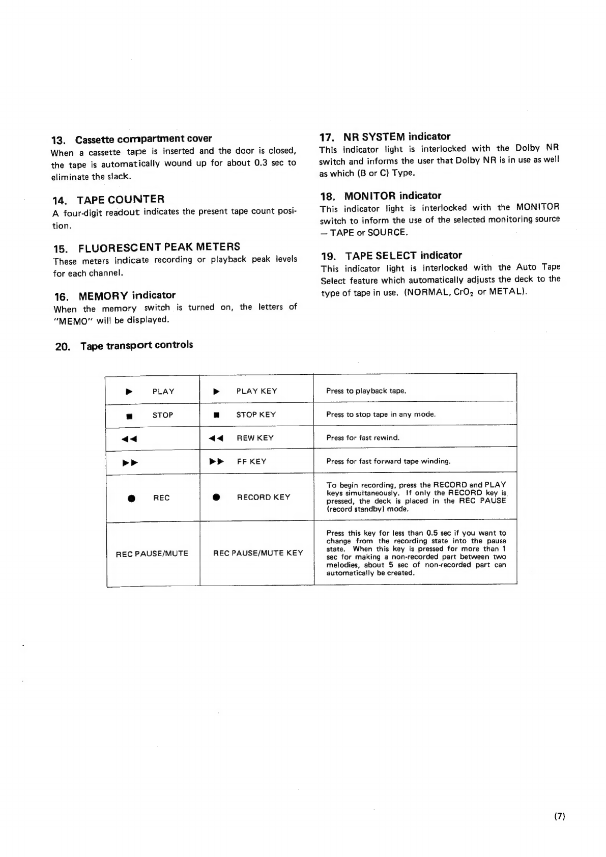
20.
Tape
transport
controls
>
PLAY
>
PLAY
KEY
>P
FFKEY
e@
REC
e
RECORD
KEY
17.
NR
SYSTEM
indicator
This
indicator
light
is
interlocked
with
the
Dolby
NR
switch
and
informs
the
user
that
Dotby
NR
is
in
use
as
well
as
which
(B
or
C)
Type.
18.
MONITOR
indicator
This
indicator
light
is
interlocked
with
the
MONITOR
switch
to
inform
the
use
of
the
selected
monitoring
source
—
TAPE
or
SOURCE.
19.
TAPE
SELECT
indicator
This
indicator
light
is
interlocked
with
the
Auto
Tape
Select
feature
which
automatically
adjusts
the
deck
to
the
type
of
tape
in
use.
(NORMAL,
CrO2
or
METAL).
a
STOP
KEY
<0
REWKEY
Press
to
playback
tape.
Press
to
stop
tape
in
any
mode.
Press
for
fast
rewind.
Press
for
fast
forward
tape
winding.
To
begin
recording,
press
the
RECORD
and
PLAY
keys
simultaneously.
!f
only
the
RECORD
key
is
pressed,
the
deck
is
placed
in
the
REC
PAUSE
{record
standby)
mode.
REC
PAUSE/MUTE
REC
PAUSE/MUTE
KEY
Press
this
key
for
less
than
0.5
sec
if
you
want
to
change
from
the
recording
state
into
the
pause
state.
When
this
key
is
pressed
for
more
than
1
sec
for
making
a
non-recorded
part
between
two
melodies,
about
5
sec
of
non-recorded
part
can
automatically
be
created.
(7)
(8)
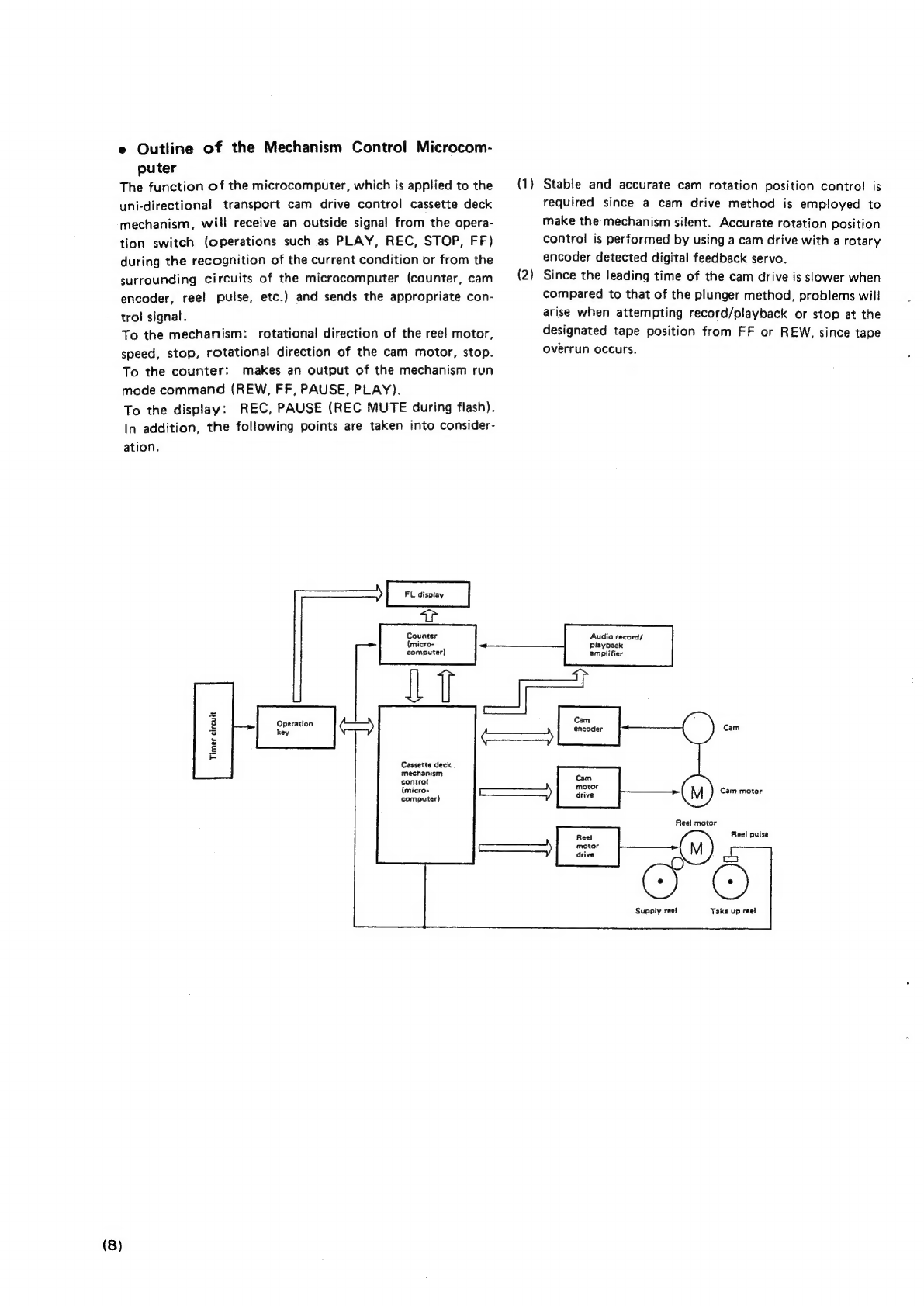
e
Outline
of
the
Mechanism
Control
Microcom-
puter
The
function
of
the
microcomputer,
which
is
applied
to
the
uni-directional
transport
cam
drive
control
cassette
deck
mechanism,
will
receive
an
outside
signa!
from
the
opera-
tion
switch
(operations
such
as
PLAY,
REC,
STOP,
FF)
during
the
recognition
of
the
current
condition
or
from
the
surrounding
circuits
of
the
microcomputer
(counter,
cam
encoder,
reel
pulse,
etc.)
and
sends
the
appropriate
con-
trol
signal.
To
the
mechanism:
rotational
direction
of
the
ree!
motor,
speed,
stop,
rotational
direction
of
the
cam
motor,
stop.
To
the
counter:
makes
an
output
of
the
mechanism
run
mode
command
(REW,
FF,
PAUSE,
PLAY).
To
the
display:
REC,
PAUSE
(REC
MUTE
during
flash).
In
addition,
the
following
points
are
taken
into
consider-
ation.
Counter
|
Se,
|
Se,
can
can
Timer
circuit
Cassette
deck
mechanism
controt
(micro-
computer)
(1)
Stable
and
accurate
cam
rotation
position
control
is
(2)
———)]
omer
drive
required
since
a
cam
drive
method
is
employed
to
make
the
mechanism
silent.
Accurate
rotation
position
control
is
performed
by
using
a
cam
drive
with
a
rotary
encoder
detected
digital
feedback
servo.
Since
the
leading
time
of
the
cam
drive
is
slower
when
compared
to
that
of
the
plunger
method,
problems
will
arise
when
attempting
record/playback
or
stop
at
the
designated
tape
position
from
FF
or
REW,
since
tape
overrun
occurs.
|
se
|
record/
|
se
|
amplifier
Ea
Ea
|
S|
Cam
motor
|
S|
Reel
motor
Reet
Reel
pulse
oge
Supply
reei
Take
up
reel

[DISASSEMBLY
INSTRUCTIONS
|
1.
How
to
Remove
the
Front
Panel
(1)
Unscrew
the
4
screws
309
from
both
sides
of
the
top
cover
240 and
take
off
the
top
cover
by
pulling
it
up.
(2)
Press
the
eject
knob
231,
open
the
cassette
window
338
and
take
off
the
mechanism,
as
shown
in
the
dia-
gram.
Note:
Be
careful
when
handling
the
cassette
window,
as
it
is
easily
scratched.
(3)
The
front
panel
can
be
removed
by
unscrewing
the
3
upper
screws
(3x8
CFTS
S
tight)
307
from
the
front
panel
233 and
the
3
lower
screws
(3x8
CBTS
P
tight)
308.
@Q
3.
How
to
Remove
the
Meter
Window
and
the
Color
Filter
2.
How
to
Remove
the
Mechanisms
(1)
Remove
the
top
cover
240
and
the
front
panel
233.
(Refer
to
section
1)
(2)
Unscrew
the
2
mechanism
holding
screws
(3x6
CBTSS
tight)
304
from
the
bottom
surface
of
the
chassis
201.
(3)
Unscrew
the
2
screws
(3x6
CBTS
§S
tight)
304
holding
the
angle
210
and
the
mechanism
207
and
the
3
chassis
holding
screws
301,
310
and
remove
the
angle.
(4)
Remove
the
connectors
with
lead
wires,
which
runs
from
the
mechanism
section,
from
the
circuit
board.
Audio
circuit
board
side
4P
connector
CN301
6P
connector
CN302
Logic
circuit
board
side
6P
connector
CN1
7P
connector
CN3
(1)
Remove
Top
Cover
(240)
and
Front
Panel
(233)
(Refer
to
Section
1)
(2)
Meter
Window
(220)
can
be
removed
by
pulling
up.
(3)
Color
Filter
(221)
can
be
removed
after
Meter
Window
(220)
is
removed.
4.
How
to
removed
the
Meter
Holder
and
the
8P
connector
CN2
Note:
When
assembling,
check
to
make
sure
the
con-
Counter/Meter
Circuit
Board,
the
LED
circuit
Board.
nectors
are
inserted
correctly.
(5)
Pull
out
the
power
switch
lever
230
from
the
power
switch
259.
(6)
Remove
the
eject
knob
231.
(1)
Remove
the
top
cover
(240)
and
the
front
panel
(233).
(Refer
to
section
1)
(2)
Remove
the
angle
(210).
(Refer
to
section
2)
(3)
Remove
the
2
screws
(3x8CFTS
S
tight)
(307)
which
(7)
The
mechanism
can
be
removed
by
holding
the
mecha-
nism
and
pulling
up.
Note:
When
assembling,
do
so
after
checking
to
make
sure
the
2
stay
holes
on
the
lower
side
of
the
mechanism
unit
are
matched
with
the
chassis
protrusions.
secure
meter
holder
(242).
Then
the
meter
holder
can
be
removed.
(4)
By
unscrewing
the
2
screws
(3x6
CBS)
(303)
holding
the
counter/meter
circuit
board,
it
can
be
removed.
(5)
By
unscrewing
the
1
screw
(3x6
CBS)
(303)
holding
the
LED
circuit
board,
it
can
be
removed.
(9)

(10)
(1)
(2)
(3)
(4)
(1)
(2)
(3)
(4)
(5)
(6)
7.
(1)
(2)
(3)
(4)
(5)
How
to
Remove
the
Front
Esc
Ass’y
Remove
the
top
cover
(240)
and
the
front
panel
(233).
(Refer
to
section
1)
Remove
the
angle
(210).
(Refer
to
section
2)
Remove
the
meter
window
(220)
and
the
color
filter
(221).
(Refer
to
section
3)
Unscrew
the
2
nuts
holding
the
output
volume
(237)
and
the
headphone
jack
(255).
Then
the
front
esc
ass’'y
(206)
can
be
removed.
How
to
Remove
the
Volume
Circuit
Board
Remove
the
top
cover
240
and
the
front
panel
233.
(Refer
to
section
1)
|
Remove
the
angle
210
(Refer
to
section
2)
Remove
the
meter
window
220
and
the
color
filter
221.
(Refer
to
section
3)
Remove
the
front
escuchion
206.
(Refer
to
section
4)
By
unscrewing
the
3
screws
(3x8
CBTS
P
tight)
301
holding
the
Volume
plate
245
and
loosening
the
2
hooks
on
the
front
escuchion
ass’y
206
holding
the
Volume
circuit
board
244,
it
can
be
removed.
Unscrew
the
3
nats
holding
the
3
Volumes.
Then
the
Volume
circuit,
board
244
can
be
removed.
How
to
Remove
the
Control
Circuit
Board
Remove
the top
cover
240
and
the
front
panel
233.
(Refer
to
Section
1)
Remove
the
angle
210.
(Refer
to
section
2)
Remove
the
meter
window
220
and
the
color
filter
221.
(Refer
to
section
3)
Remove
the
front
escuchion
206.
(Refer
to
section
4)
By
unscrewing
the
3
screw
(3x8
CBTS
P
tight)
301
holding
the
control
circuit
board
and
loosening
the
2
hooks
on
the
front
escuchion
Ass’y
206
holding
the
control
circuit
board
204,
it
can
be
removed.
Note:
8.
(1)
(2)
(3)
(4)
(5)
(6)
(7)
(8)
(9)
When
replacing
the
tact
switch
224,
always
check
to
make
sure
that
it is
not
floating
above
the
circuit
board.
If it
is
floating,
the
switch
will
be
in
the
on
condition
when
the
set
is
assembled.
O
x
Be
cca
ges
How
to
Remove
the
Audio
Circuit
Board
Remove
the
top
cover
240
and
the
front
panel
233.
(Refer
to
section
1)
Remove
the
angle
210
(Refer
Remove
the
meter
holder
242,
Remove
the
front
escuchion
206.
Remove
the
volume
plate
245.
(Refer
to
section
6)
Remove
the
control
circuit
board
204.
(Refer
to
section
7)
Remove
the
connectors
from
the
audio
circuit
board
203.
to
section
2)
(Refer
to
section
4)
Unscrew
the
4
bottom
cover
holding
screws
(3x8
CBTS
P
tight)
301
on
the
back
side
of
the
chassis
201
and
remove
the
bottom
cover
218.
By
loosening
the
2
hooks
on
the
chassis
holding
the
audio
circuit
board
203,
the
audio
circuit
board
can
be
removed.
Note:
Most
repairs
to
the
audio
circuit
board
can
be
performed
by
removing
the
bottom
cover
on
the
chassis.
Refer
to
the
above
procedure
only
when
necessary.
When
reassembling,
follow
the
procedures
in
reverse
order;
however,
if
each
of
the
various
parts
are
not
assembled
properly
in
their
respective
position,
the
set
cannot
be
assembled.
When
assembling,
check
the
work
of
each
step
carefully.
(1)
(2)
(3)
(4)
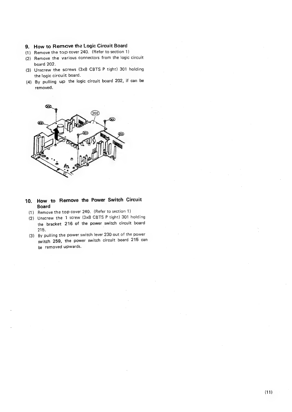
How
to
Remove
the
Logic
Circuit
Board
Remove
the
top
cover
240.
(Refer
to
section
1)
Remove
the
various
connectors
from
the
logic
circuit
board
202.
Unscrew
the
screws
(3x8
CBTS
P
tight)
301
holding
the
logic
circuit
board.
By
pulling
up
the
logic
circuit
board
202,
if
can
be
removed.
10.
(1)
(2)
(3)
How
to
Remove
the
Power
Switch
Circuit
Board
Remove
the
top
cover
240.
(Refer
to
section
1)
Unscrew
the
1
screw
(3x8
CBTS
P
tight)
301
holding
the
bracket
216
of
the
power
switch
circuit
board
215.
,
By
pulling
the
power
switch
lever
230
out
of
the
power
switch
259,
the
power
switch
circuit
board
215
can
be
removed
upwards.
(11)

ADJUSTING
AND
CHECKING
THE
MECHANISM
SECTION
1.
Replacing
the
Pinch
Roller.
Before
replacing
the
pinch
roller,
clean
the
tape
contact
surface
of
the
pinch
roller
and
the
capstan
shaft.
Most
causes
of
poor
tape
transport
can
be
traced
to
dirty
pinch
rollers
and
capstan
shafts.
The
right
side
pinch
roller
23
can
be
taken
out
by
remov-
ing
spring
24
and
slit
washer
317.
In
the
same
manner,
the
left
side
pinch
roller
104
can
be
taken
out
by
remov-
ing
spring
106
and
slit
washer
317.
After
replacing,
play
a
padiess
C-90
tape
and
check
for
tape
curls
at
the
head
tape
guide
section.
In
addition,
in
the
playback
mode,
check
to
make
sure
that
the
right
side
pinch
roller
contacts
the
capstan
shaft
before
the
left
side
pinch
roller
contacting.
Correct
P,
Rolter
arm
L
C_]
/
2
nut
Tape
guide
P.
Roller
arm
R
2
nut
E.
head
Special
nut
Reha
Defective
Curled
Curled
Tape
travel
2.
Checking
the
Pressure
Force
of
the
Pinch
Roller
In
the
playback
mode,
hook
a
spring
weight
onto
the
bracket
at
the
center
of
the
pinch
roller.
After
separating
the
pinch
roller
from
the
capstan
shaft,
allow
the
pinch
roller
to
contact
the
capstan
shaft
again.
When
the
pinch
roller
starts
to
rotate,
check
to
make
sure
the
rod
type
spring
weight
reading
is
350g—450g
for
the
right
side
and
150g
~
250g
for the
left
side.
Hf
it
is
not
within.the
normal
range,
replace
the
pinch
roller
spring
24
or
106.
Pinch
roller
spring
Capstan
shaft
Pinch
roller
Left
side
{50g
~
250g
(12)
3.
Replacing
the
Record/Playback
Head
*
Before
replacing,
remove
the
front
panel
233.
(1)
How
to
remove
the
R/P
HEAD.
1)
Next,
Take
out
the
azimuth
adjustment
NUT
311,
tilt
adjustment
NUT
311,
and
the
height
adjustment
Special
nut
10
loosening
them
alternately.
If
they
are
not
loosened
alternately,
the
R/P
HEAD
base
may
become
warped.
2)
By
unsoldering
the
HEAD
WIRES
on
the
circuit
board
section
of
the
R/P
HEAD,
the
entire
R/P
HEAD
can
be
taken
off
the
mechanism
unit.
C@
R/P
head
er
(Azimuth
adj,
nut)
(Tilt
adj.
nut)
(2)
How
to
assemble
the
R/P
HEAD.
Reverse
the
above
(1)
procedures
for
removing
the
R/P
HEAD.
“Solder
the
HEAD
WIRES
according
to
the
diagram
above.
4.
Adjusting
the
R/P
HEAD
(1)
Height
adjustments
(Use
the
head
adjusting
jig
THG-801
1)
Set
the
THG-801
tooi
plate
on
the
mechanism
unit;
turn
the
height
adjustment
Special
nut
10
and
adjust
so
that
the
3.8
mm
measure
section
of
the
THG-801
(tool
grip)
can
pass
without
contacting
the
tape
guide
of
_
the
R/P
HEAD
9.
2)
When
adjusting
the
height,
make
sure
the
R/P
HEAD
is
not
tilted
by
turning
the
azimuth
adjustment
nut
311
nut,
and
checking
with
your
eyes.
*Never
allow
the
THG-801
(tool
grip)
to
hit
the
tape
contact
surface
of
the
R/P
HEAD
strongly.
It
may
scratch
the
surface.

(2)
Adjusting
Tilt
Angle
1)
Set
the
THG-801
Tool
Plate
on
the
Mechanism
Unit
and
then
place
the
THG-801
Tool
Grip
on
the
R/P
Head,
and
check
the
Tilt
Angle
between
THG-801
Tool
Plate
and
THG-801
Tool
Grip.
If
the
THG-801
Tool
Grip
is
tilting
toward
the
front,
loosen
Tilt
with
nut
(311).
If
the
THG-801
(Tool
Grip)
is
tilting
toward
the
rear,
tighten
it.
Adjust
the
Tilt
Adjustment
nut
(311)
until
the
THG-801
Tool
Grip
becomes
parallel
with
the
THG-801
Tool
Plate.
lf
the
Tilt
Angle
is
adjusted
more
than
once,
height
Adjustment
may
slip.
Always
make
sure
to
check
height
adjustment.
—
If
height
has
slipped,
adjust
it
again.
After
adjustment,
fix
screw.
2)
E\
Tilt
Angle
Tool
grip
Tool
grip
B-
Tool
Plate
Tool
Plate
Tilt
Angle
(3)
Azimuth
adjustments
Play
back
the
A*‘BEX
TCC-153
test
tape.
Turn
the
azimuth
adjustment
nut
and
adjust
so
that
A
of
the
resurge
wave
form
is
maximum
and
B
is
minimum.
After
the
azimuth
adjustments,
re-check
the
head
height
with
the
THG-801
to
make
sure
the
height
has
not
deviated.
MTT
114
*
After
the
adjustments,
apply
anaerobic
adhesive
on
the
positions
indicated
in
the
diagram.
Anaerobic
adhesive
Anaerobic
adhesive
5.
Adjustment
and
Replacement
of
Erasing
Head
(1)
Height
Adjustments
Set
the
THG-801
Tool
Plate
on
the
mechanism
unit.
Using
a
surface
measure
of
3.8
mm
from
the
THG-801
Tool
Grip,
turn
adjustment
nut
(311)
and
(171)
and
adjust
the
height
of
Erasing
Head’s
center
to
coincide
with
the
center
of
the
THG-801
Tool
Grip.
After
adjustment,
place
the
THG-801
Tool
Grip
on
the
Erasing
Head,
check
to
see
that
the
THG-801
Tool
Plate
and
the
THG-801
Tool
Grip
are
parallel,
and
that
the
Tilt
Angle
has
not
changed.
Lock
after
adjustment.
Tilt
Angle
Adjustment
Set
the
THG-801
Tool
Plate
on
the
mechanism
unit.
Place
the
THG-801
Tool
Grip
on
the
Erasing
Head,
and
check
the
gap
between
the
THG-801
Tool
Plate
and
the
Tool
Grip.
tf
the
THG-801
Tool
Grip
is
tilting
toward
the
front,
loosen
the
Tilt
adjustment
nut
(311).
\f
it
is
tilting
toward
the
rear,
tighten
it
and
adjust
the
Tilt
adjustment
nut
(311)
until
the
THG-801
Tool
Grip
becomes
parallel!
with
the
THG-801
Tool
Plate.
(2)
CAUTION:
After
adjusting
the
Tilt
Angle,
height
adjust-
ment
may
sometimes
be
warped.
Recheck
height
adjustment.
If
it
is
warped,
readjust
the
height.
After
adjusting,
fix
nuts
(311)
and
(171).
(3)
Erasing
Head
Replacement
Erase
Head
may
be
replaced
after
removing
nuts
(311)
and
(171)
which
affix
it
to
the
deck
mechanism,
After
replacement,
adjust
the
height
and
the
Tilt
angle.
3.8mm
Tilt
Angle
6.
Height
Adjustment
of
the
Tape
Guide
Set
the
THG-801
jig
plate
onto
the
mechanism
unit
and
ad-
just
the
height
by
rotating
the
height
adjustment
nut
311
so
that
the
3.8mm
section
of
the
THG-801
jig
can
pass
through
without
contacting
the
tape
guide
section
of
tape
guide
103.
7.
Checking
the
Take-up
Torque
Load
the
cassette
type
torque
meter.
Check
to
make
sure
that
the
torque
meter
average
reading
is
within
40
~
80
g-cm
during
playback.
If
it
is
not
within
this
range,
check
the
voltage
(4.3V
+
0.3V)
of
the
reel
motor.
If
the
voltage
is
low,
the
torque
will
be
weak;
if
it
is
high,
the
torque
will
be
strong.
in
addition,
check
for
reel
thrust
movement
in
section
8.
(13)
8.
Adjusting
the
Reel
Thrust
Movement
Check
to
make
sure
that
the
reel
thrust
movement
is
within
0.2—0.4
mm.
9.
Checking
the
FF
and
REW
Torques
*
When
using
the
cassette
type
torque
meter.
Check
to
make
sure
the
torque
meter
indicates
more
than
80
~
160
g-cm
at
the
end
of
FF
and
REW.
*
When
using
a
modified
cassette
half.
Load
the
modified
cassette
half;
hook
the
end
of
the
dial
tension
meter
(full
scale
100—300
g)
onto
the
triangle
section.
In
the
FF
(REW)
mode,
feed
the
tape
in
at
a
rate
somewhat
slower
than
the
take
up
speed.
Check
to
make
sure
the
dial
tension
meter
reads
more
than
60
g-cm.
10.
Checking
the
Back
Tension
Torque
During
Record/Playback
Load
the
cassette
type
torque
meter;
check
to
make
sure
the
torque
meter
reads
between
5
~
13
g-cm
during
play-
back
and
that
there
js
rio
unevenness.
If
it
is
not
within
this
range,
check
the
section
on
adjust-
ing
the
reel
trust
movement;
or
replace
the
spring
109.
11.
Checking
the
FF
and
REW
Times
Load
a
C-60
cassette
tape;
check
to
make
sure
the
tape
is
fast
forwarded
or
rewound
within
70—110
seconds.
If
it
is
not
within
this
range,
check
sections
8
and
10.
12.
Checking
the
Operation
of
the
Erase
Preven-
tion,
Metal
and
Chrome
Switch
Operation
Arms
Check
to
make
sure
the
operation
arms
58,
59
operate
the
switches
positively;
depending
on
whether
or
not
there
are
holes.
13.
Checking
the
EJECT
Switch
To
check
the
operation
of
the
EJECT
SW
with
only
the
mechanism
unit,
make
sure
the
angle
205
operates
the
switch
positively
when
the
hook
lever
203
is
operated.
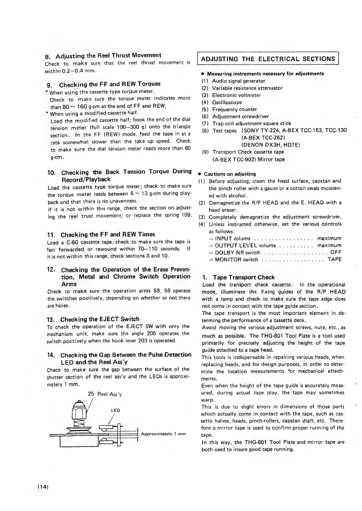
14.
Checking
the
Gap
Between
the
Pulse
Detection
LED
and
the
Reel
Ass’y
Check
to
make
sure
the
gap
between
the
surface
of
the
shutter
section
of
the
reel
ass’y
and
the
LEDs
is
approxi-
mately
1
mm.
25
Reel
Ass’y
LED
Z
Approximately
1mm
(14)
ADJUSTING
THE
ELECTRICAL
SECTIONS
@
Measuring
instruments
necessary
for
adjustments
(1)
Audio
signal
generator
(2)
Variable
resistance
attenuator
(3)
Electronic
voltmeter
(4)
Oscilloscope
(5)
Frequency
counter
(6)
Adjustment
screwdriver
(7)
Trap
coil
adjustment
square
stick
(8)
Test
tapes
(SONY
TY-224,
A-BEX
TCC-153,
TCC-130
(A-BEX
TCC-262)
(DENON
DX3H,
HD7E)
(9)
Transport
Check
cassette
tape
(A-BEX
TCC-902)
Mirror
tape
@
Cautions
on
adjusting
(1)
Before
adjusting,
clean
the
head
surface,
capstan
and
the
pinch
roller
with
a
gauze
or
a
cotton
swab
moisten-
ed
with
alcohol.
Demagnetize
the
R/P
HEAD
and
the
E.
HEAD
with
a
head
eraser.
(2)
(3)
Completely
demagnetize
the
adjustment
screwdriver.
(4)
Unless
instructed
otherwise,
set
the
various
controls
as
follows:
—
INPUT
volume
..........-.--0065
maximum
—
OUTPUT
LEVEL
volume
..........
maximum
—
DOLBY
NRswitch
...............06.
OFF
—
MONITOR
switch
............0.0005
TAPE
1.
Tape
Transport
Check
Load
the
transport
check
cassette.
In
the
operational
mode,
illuminate
the
fixing
guides
of
the
R/P
HEAD
with
a
lamp
and
check
to
make
sure
the
tape
edge
does
not
come
in
contact
with
the
tape
guide
section.
The
tape
transport
is
the
most
important
element
in
de-
terming
the
performance
of
a
cassette
deck.
Avoid
moving
the
various
adjustment
screws,
nuts,
etc.,
as
much
as
possible.
The
THG-801
Tool
Plate
is
a
tool
used
primarily
for
precisely
adjusting
the
height
of
the
tape
guide
attached
to
a
tape
head.
This
tools
is
indispensable
in
repairing
various
heads,
when
replacing
heads,
and
for
design
purposes,
in
order
to
deter-
mine
the
location
measurements
for
mechanical
attach-
ments.
Even
when
the
height
of
the
tape
guide
is
accurately
meas-
ured,
during
actual
tape
play,
the
tape
may
sometimes
warp.
This
is
due
to
slight
errors
in
dimensions
of
those
parts
which
actually
come
in
contact
with
the
tape,
such
as
cas-
sette
halves,
heads,
pinch-rollers,
capstan
shaft,
etc.
There-
fore
a
mirror
tape
is
used
to
confirm
proper
running
of
the
tape.
In
this
way,
the
THG-801
Tool
Plate
and
mirror
tape
are
both
used
to
insure
good
tape
running.
After
having
confirmed
that
the
setting
is
correct,
the
mir-
ror
tape
may
warp
anyway.
In
order
to
establish
the
titit
angles
of
the
recording/plaback
head
and
the
erase
head,
adjust
(by
turning
1
/4
—
1/2
turns)
the
level
adjustment
nut
(811)
of
the
tape
guide
(103).
Refer
to
the
pages
on
“Adjusting
and
checking
the
Mechanism
Section’
when
replacing
or
adjusting
the
R/P
HEAD.
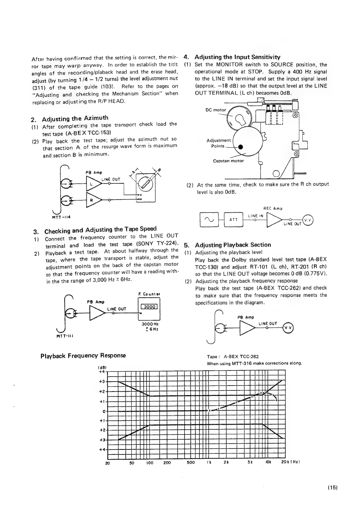
2.
Adjusting
the
Azimuth
(1)
After
completing
the
tape
transport
check
load
the
test
tape
(A-BE
X
TCC-153)
(2)
Play
back
the
test
tape;
adjust
the
azimuth
nut
so
that
section
A
of
the
resurge
wave
form
is
maximum
and
section
B
is
minimum.
MTT
=114
3.
Checking
and
Adjusting
the
Tape
Speed
1)
Connect
the
frequency
counter
to
the
LINE
OUT
terminal
and
load
the
test
tape
(SONY
TY-224).
2)
Playback
a
test
tape.
At
about
halfway
through
the
tape,
where
the
tape
transport
is
stable,
adjust
the
adjustment
points
on
the
back
of
the
capstan
motor
so
that
the
frequency
counter
will
have
a
reading
with-
in
the
the
range
of
3,000
Hz
+
6Hz.
F
Counter
PB
Amp
LINE
OUT
3000
Hz
,6Hz
MTT-Ii
Playback
Frequency
Response
4.
Adjusting
the
Input
Sensitivity
(1)
Set
the
MONITOR
switch
to
SOURCE
position,
the
operational
mode
at
STOP.
Supply
a
400
Hz
signal
to
the
LINE
IN
terminal
and
set
the
input
signal
level
(approx.
—18
dB)
so
that
the
output
level
at
the
LINE
OUT
TERMINAL
(L
ch)
becaomes
OcB.
DC
motor
#
VA
Adjustment
Points
Capstan
motor
(2)
At
the
same
time,
check
to
make
sure
the
R
ch
output
level
is
also
OdB.
REC
Amp
LINE
IN
:
©
LINE
OUT
5.
Adjusting
Playback
Section
(1)
Adjusting
the
playback
level
Play
back
the
Dolby
standard
level
test
tape
(A-BEX
TCC-130)
and
adjust
RT-101
(L
ch),
RT-201
(R
ch)
so
that
the
LINE
OUT
voltage
becomes
0
dB
(0.775V).
Adjusting
the
playback
frequency
response
Play
back
the
test
tape
(A-BEX
TCC-262)
and
check
to
make
sure
that
the
frequency
response
meets
the
specifications
in
the
diagram.
(2)
PB
Amp
LINE
OUT
J
Tape:
A-BEX
TCC-262
When
using
MTT-316
make
corrections
along.
10k
20k
(Hz)
(15)
6.
Adjusting
the
FL
Meter
After
adjusting
the
playback
level,
playback
the
test
tape
(A-BEX
TCC-130)
and
adjust
RT401
(L
ch),
RT402
(R
ch)
so
that
the
FL
meter
indicates
OdB
when
the
LINE
OUT
terminal
level
is
OdB
(0.775V).
LINE
OUT
MTT-150
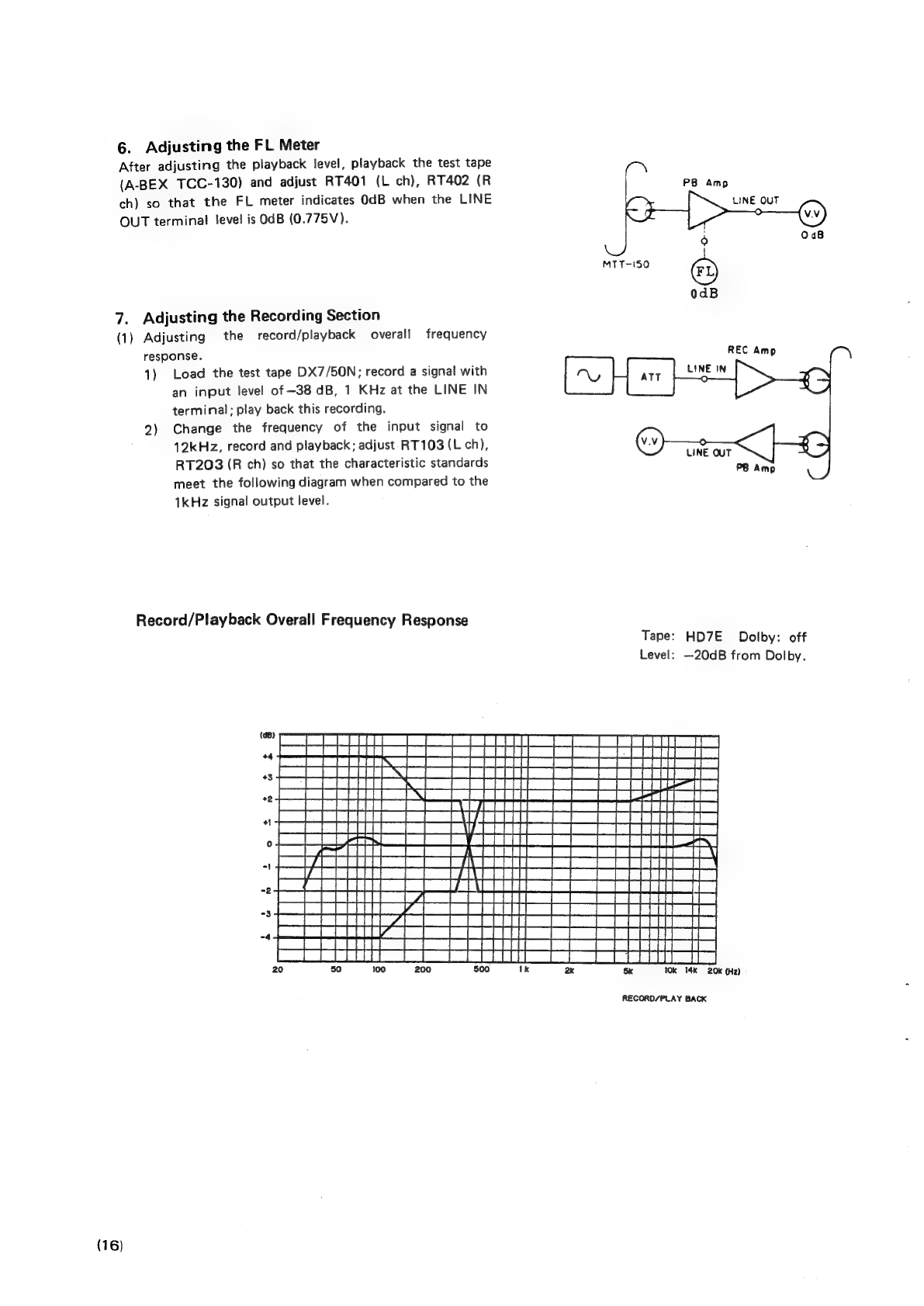
7.
Adjusting
the
Recording
Section
(1)
Adjusting
the
record/playback
overall
frequency
response.
1)
Load
the
test
tape
DX7/50N;
record
a
signal
with
an
input
level
of
-38
dB,
1
KHz
at
the
LINE
IN
terminal;
play
back
this
recording.
2)
Change
the
frequency
of
the
input
signal
to
12kHz,
record
and
playback;
adjust
RT103
(L
ch),
RT203
(R
ch)
so
that
the
characteristic
standards
meet
the
following
diagram
when
compared
to
the
1kHz
signal
output
level.
Record/Playback
Overall
Frequency
Response
Tape:
HD7E
Dolby:
off
Level:
—20dB
from
Dolby.
Sk
10k 14k
20k
(Hz)
RECORD/PLAY
BACK
(16)
(2)
Adjusting
the
record/playback
levels
1)
Load
the
test
tape
HD7E/C-60
and
record
a
signal
of
1kHz
(—38
dB).
2)
Adjust
RT102
(L
ch),
RT202
(R
ch)
so
that
the
output
level
is
the
same
when
the
MONITOR
switch
is
switched
from
SOURCE
to
TAPE
position.
LINE
OUT
PB
Amp
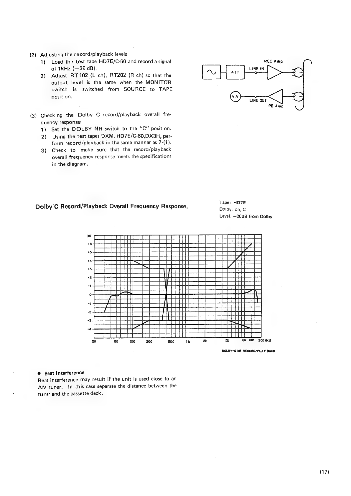
(3)
Checking
the
Dolby
C
record/playback
overall
fre-
quency
response
1)
Set
the
DOLBY
NR
switch
to
the
“C”
position.
2)
Using
the
test
tapes
OXM,
HD7E/C-60,DX3H,
per-
form
record/playback
in
the
same
manner
as
7-(1).
3)
Check
to
make
sure
that
the
record/playback
overall
frequency
response
meets
the
specifications
in
the
diagram.
Tape:
HD7E
Dolby:
on,
C
Level:
—20dB
from
Dolby
Dolby
C
Record/Playback
Overall
Frequency
Response.
(<8)
i
fm
_tttitt
|
[|
TT
a
oe
Ee
Tr
+4
+3
+2
+1
al
-3
aa
i
“4
ee
eee
Pai
ERR
Se
En
FS
Ol
(Fa
ett
aaa
PS)
tH
4
a
sO
De
20 50
100
200 500
1k
2k
5k
Wk
14k
20k
(Hz)
DOLBY~C
NR
RECORD/PLAY
BACK
@
Beat
Interference
Beat
interference
may
result
if
the
unit
is
used
close
to
an
AM
tuner.
In
this
case
separate
the
distance
between
the
tuner
and
the
cassette
deck.
(17)
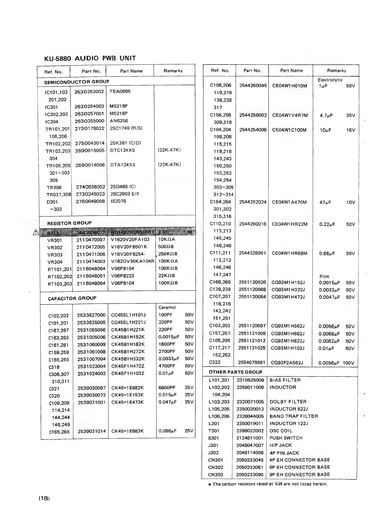
KU-5880
AUDIO
PWB
UNIT
Ref.
No.
Part
No.
Part
Name
Remarks
Ref.
No.
Part
No.
[te
Name
Remarks
_—_t
Electrolytic
Semone
ere
7
C106,206
|
2544260045|
CE04W1H010M
1uF
:
50V
1c101,102
|
2630353002
|}
TEAO6ES5
119,219
201,202
138,238
1C301
2630284003
|
M5219P
317
1C302,303
|
2630257001
|
M5218P
C156,256
|
2544258002)
CEO4W1V4R7M
4.7nF
35V
1C304
2630355000
|
AN6256
309,319
TR101,201)
2730178022
|
2SC1740
(R/S)
C104,204
|
2544254006!
CE04W1C100M
10uF
16V
106,206
108,208
TR102,202|
2750043014
|
2SK381
(C/D)
115,215
TR103,203}
2690015005
|
DTC124xs
(22K-47K)
118,218
304
143,243
TR105,205|
2690014006
|
DTA124XS
(22K-47K)
150,250
301~303
153,253
305
154,254
TR306
2740036002
|
2SD468
(C)
303~305
TRO37,308)
2730245023
}
2SC2603
E/F
312~314
D301
2760049008
|
1S2076
C164,264
|
2544252024|
CE04W1A470M
47uF
10V
~303
301,302
315,316
RESISTOR
C110,210
|
2544260016]
CEO4W1HR22M
0.22uF
50V
3
113,213
VR301
2110470007
|
V1620V20FA103
|
10KQA
145,245
VR302
2110472005
|
V16V20FB501K
50028
148,248
VR303
2110471006
|
V16V20FB8254-
=
|
250K2.B
C111,211
|
2544228951}
CEO4W1HR68M
0.68uF
50V
VR304
2110474003
|
Vi62DV30KA104R|
100KQA
112,212
RT101,201}
2116048064
|
VO6PB104
100K2B
146,246
RT102,202/
2116048051
|
Vo6PB223
22K2B
147,247
Film
RT103,203}
2116048064
|
VO6PB104
100K2.B
C166,266
|
2551120026;
CQ93M1H152J
0.0015uF
50V
C139,239
|
2551120068|
CQ93M1H332J
0.0033uF
50V
CAPACITOR
GROUP
C107,207
|
2551120084]
CQ93M1H472J
0.0047uF
50V
oat
Ceramic
Bae
142,242
¢102,202
|
2533627000
|
CC45SL1H101J
100PF
151.251
C101,201
|
2533635005
|
CC45SL1H221J
=|
220PF
=
50V
C103,203
|
2551120097!
CQ93M1H562J
0.0056uF
50V
C18
7267
|||
ee
Onan
Oe
Glee
beats
are
oY
C157,257
|
2551121009}
CQ93M1H682J
0.0068uF
50V
C163,263
|
2531005006
|
CK45B1H152K
0.0015uF
50V
"
;
c1et261
|
2831060009
|
cK4sB1H182K
1GOORE:.
600
C105,205
|
2551121012)
CQ93M1H822J
0.0082uF
50V
'
C117,217
|
2551121025|
CQ93M1H103J
0.01uF
50V
¢159,259
|
2531061008
|
CK45B1H272K
2700PF
50V
eye
C155,255
|
2531007004
|
CK45B1H332K
0.0033uF
SOV
(318
2531023004
|
CK45F1H472Z
4700PF
50V
ie
P5080
R081)
COBSEZABG2I.
|
0.0056uF
-190¥
|
¢306,307
|
2531024003
|
CK45F1H103Z
0.01uF
50V
OTHER
PARTS
GROUP
310,311
101,201
|
2310825009
|
BIAS
FILTER
|
(321
2539030057
|
CK45=1E682K
6800PF
25V
L102,202
|
2358011008
|
INDUCTOR
320
2539030073
|
CK45=1E153K
0.015uF
25V
104,204
€109,209
|
2539031001
|
CK45=1E473K
0.047uF
25V
L103,203
|
2320071005
|
DOLBY
FILTER
114,214
L105,205
|
2350020013
|
INDUCTOR
822J
144,244
L106,206
|
2328044005
|
BAND
TRAP
FILTER
149,249
L301
2350019011
|
INDUCTOR
122J
€165,265
|
2539031014
|
CK45=1E683K
0.068uF
25V
7301
2398022002
|
OSC
COIL
—!
i
$301
2124611001
|
PUSH
SWITCH
J301
2048047007
|
H/P
JACK
J302
2048114008
|
4P
PIN
JACK
CN301
2050233045
|
4P
EH
CONNECTOR
BASE
CN302
2050233061
|
6P
EH
CONNECTOR
BASE
CN303
2050233090
|
9P
EH
CONNECTOR
BASE
(18)
@
The
carbon
resistors
rated
at
%“W
are
not
listed
herein.

KU-5870
POWER
LOGIC
UNIT
|
Part
No.
|
Part
Name
Remarks
Tr
|
RESISTOR
GROUP
yPD7506C-69
BA6109U1
BA6146
pPD554C-136
2S8D468
(C)
2SD882
(Q/P)
28C1740
(R/S)
288772
Q/P
2S8A933
(R/S)
2SA966
(Y)
DTA143ES
DTC124XxS
2S8C1740
(R/S)
DTC124XS
DTA143ES
28C1740
(R/S)
28C1740
(R/S)
RN1204
DTC124xS
DSM1A2
1S2076A
1S2076
HZ11A-3
H2Z18-3
HZ5B-3
HZ7B-3
HZ9B-1
HZ3C-2
Ref.
No.
F
SEMICONDUCTOR
GROUP
1C1
2620674005
1C2,3
2620447009
1C401,
402
|
2620440006
1C403
2620580005
TR1
2740036002
TR2
2740078031
TR3
2730178022
TR4
2720055029
TRS
2710183927
TR6
2710105002
TR7
2690022904
TR8
2690015005
TRO
2730178022
TR11
269001
5005
TR12
2690022904
TR13
2730178022
TR404
27301
78002
TR405
2690029004
TR451
2690015005
D1~10
2760433009
D11
2760049011
D12~20
2760049008
D401,
402
D451~456
ZD1,
2
2760052082
ZD3
2760249015
ZD5
2760236015
ZD6
2760254000
ZD7
2760218046
ZD8
2760299007
=
4,.7K-4.7K
22K-47K
22K-47K
4,.7K-4.7K
47K-47K
22K-47K
R29
Src
ere
een
182
R427
2412313082
|
RD14B2E4R7JFRF|
4.72
RB401
2462013002
|
RK99=2B473MP5
|
47K2x5
RB402
2462010092
|
RK99=28104mMP4
|
100K2x4
RB403
2462012032
|
RK99=2B104MP8
|
100K2x8
RT401,
402]
2116048019
|
VO6PB473
47KQB
CAPACITOR
GROUP
poe
C1,9
|
254284006
CE04W1C100M
10nF
16V
408
C2
2544260045
|
CEO4W1H010M
1yF
50V
C3,6
2544252024
|
CE04W1A470M
47uF
10V
C4,
7
2544254938
|
CE04W1C470M
47uF
16V
C5,
8
2544254080
|
CE04W1C102M
1000uF
16V
15
C10,
11
2544256033
|
CE04W1E470M
47uF
25V
c12
2544258086
|
CE04W1C471M
470uF
35V
C13
2544163003
|
CE04W1C221M
220uF
16V
C14
2544255018
|
CE0Q4W1C472M
4700zF
=
16V
C16,
17
2544258002
|
CEO4W1V4R7M
4.74uF
35V
20,
401,
i
AOA»
-A)-¢
2
aes
Ref.
No.
Part
No.
C18
2539031014
|
CK45=1E683K
30,
33
c19
2544250055
|
CE04W0J471M
C21~25
2531004007
|
CK45B1H102K
C28~32
2531024003
|
CK45F1H103Z
C402,405
|2544260058
|
CE04W1H2R2M
C403,
406
|
2544254019
|
CEO04W1C220M
C407
2544252943
|
CEO04W1A221M
C409,
410
|2531006005
|
CK45B1H222K
C411
2531025002
|
CK45F1H223Z
CB1
2531153000
|
CK99B1H102MP4
__
OTHER
PARTS
GROUP
4170253013
|
RADIATOR
2050233061
|
6P
EH
CONNECTO
BASE
CN2
2050233087
|
8P
EH
CONNECTOR
BASE
CN3
2050233074
|
7P
EH
CONNECTOR
BASE
CN401
2050233090
|
9P
EH
CONNECTOR
BASE
CN402
2050233045
|
4P
EH
CONNECTOR
BASE
,
LE451
3939355001
|
LN224RP
(LS)
LE452
3939354002
|
LN424YP
(LS)
LE453
3939352004
|
LN324GP
(LS)
SW451~458]
2124388004
|
TACT
SWITCH
4430537000
|
LED
GUIDE
L401
2358014034
|
tNDUCTOR
3934010008
|
FL
METER
4410667107
|
METER
HOLDER
Part
Name
Remarks
0.068uF
470uF
1000PF
0.01uF
2.2nF
22uF
220uF
2200PF
0.022uF
0.001
uF
25V
6.3V
50V
50V
50V
16V
10V
50V
50V
50V
1
2204
H
@
The
carbon
resistors
rated
at
“W
are
not
listed
herein.
WARNING
Se
Parts
marked
with
/\
and/or
shading
have
special
charac-
teristics
important
to
safety.
Be
sure
to
use
the
specified
parts
for
replacement.
(19)
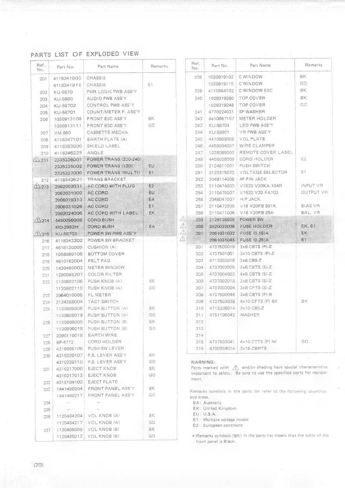
PARTS
LIST
OF
EXPLODED
VIEW
fee
tee
ek
|
oe
T
Ref.
|
Part
No.
|
Part
Name
|
Remarks
No.
\
|
201}
4118341903
|
CHASSIS
|
|
4118341916
|
CHASSIS
Et
|
202
|
KU-5870
|
PWR
LOGIC
PWB
ASS'Y
|
|
203}
KU-5880
|
AUDIO
PWB
ASS'Y
|
|
204)
KU-58702
|
CONTROL
PWBASS'Y
|
|
208)
KU-58701
|
COUNT/METER
P.
ASS’Y
|
|
206|
1030913108
|
FRONT
ESC
ASS'Y
|
BK
|
1030913111
FRONT
ESC
ASS'Y
|
Go
|
207
VM
860
|
CASSETTE
MECHA
|
|
208
4118347101
|
EARTH
PLATE
(A)
|
209|
4118383000
|
SHIELD
LABEL
210|
41183
5
4118343302
|
4618130009
1058089108
4610162004
|
1430460002
|
1290065207
|
4130802106
|
4130802119)
3984010008
|
2124388004
|
1130806005
|
1430806018
297
|
2090110018
|
|
298
|
EP-4772
|
229)
4318098108
230
|
4310220107
|
_
43102201
10)
1130805006
|
Pl
1130805019
|
|
POWER
SW
BRACKET
CUSHION
(A)
BOTTOM
COVER
FELT
PAD
METER
WINDOW
COLOR
FILTER
PUSH
KNOB
(A)
PUSH
KNOB
(A)
FLMETER
EARTH
WIRE
CORD
HOLDER
PUSH
SW
LEVER
P.S.
LEVER
ASS’Y
P.S.
LEVER
ASS'Y
EJECT
KNOB
EJECT
KNOB
EJECT
PLATE
FRONT
PANEL
ASS'Y
FRONT
PANEL
ASS’Y
VOL
KNOB
(A)
VOL
KNOB
(A)
VOL
KNOB
(B)
VOL
KNOB
(B)
OA
Q
w
Q
wow
aq
w
A
OA
¢
G)
w
OA
QQ
w
OR
231
|
4310217000
|
|
4310217013
|
|
232)
4318104102)
33
|
1441480204
|
1441480217
|
|
234
|
~
}
235
|
=
236
|
1120484204
|
|
1120484217,
237
|
1120485009
|
|
|
1120485012
|
|
ret.
Part
No.
|
Part
Name
|
Remarks
|
238)
1030919102
|
c
WINDOW
|
BK
|
|
7030919115
|.C
WINDOW
|
Go
239
|
4110564102
|
C
WINDOW
ESC
BK
240
|
1028319280
|
TOP
COVER
|
BK
|
1028319248
TOP
COVER
|
Go
241
|
4770224031
|
SP
WASHER
|
242
4410667107
|
METER
HOLDER
|
243)
KU-58704
|
LED
PWB
ASS’Y
244
KU-58801
~~
VR
PWB
ASS'Y
|
245
4410668009
VOL
PLATE
|
246
4458004007
|
WIRE
CLAMPER
|
247)
1338085000
|
REMOTE
COVER
LABEL
|
248
|
4458028009
CORD
HOLDER
|
£2
250
|
2124611001}
PUSH
SWITCH
251
|
2123315023
|
VOLTAGESELECTOR
|
£1
252
2048114008
4P
PIN
JACK
253
|
2110474003
|
V1620 V30KA
104R
|
INPUT
VR
254
2110470007
|
V1620
V20
FA103
OUTPUT
VR
255
|
2048047007
|
H/P
JACK
257.
2110472005
V16
V20FB
501K
BIAS
VR
2110471006
|
V16
V20FB
254-
|
2129136028
4737500015’
|
3x8
CBTS
(P)-Z
302
4737501001
|
3x10
CBTS
(P)-Z
303
4713303016
|
3x6
CBS-Z
304
|
4737002005
3x6
CBTS
(S)-Z
305
4737004003
4x8
CBTS
(S)-Z
308
4737002018
3x8
CBTS
(S)-Z
307
|
4737003004
|
3x8
CFTS
(S)
|
308
|
4737500044
|
3x8
CBTS
(P)-B
309
4737503038
4x10
CFTS
(P)
BK
|
BK
310
4713305014
|
3x10
CBS-Z
311.)
4751106042
|
WASHER
312
|
|
313
|
314
|
|
|
|
315
|
4737503041
|
4x10
CTTS
(P)
NI
/
GO
|
316]
3x16
CBRTS
|
4730359014
|
WARNING:
Parts
marked
with
/\
important
to
safety.
Be
ment.
and/or
shading
have
special
characteri
sure
to
use
the
specified
parts
for
replace-
Remarks
symbols
in
the
parts
list
and
areas,
EA:
Australia
Ek:
United
Kingdom
EU:
USA,
E1:
Multiple
voltage
mode!
E2:
European
continent
*
Remarks
symbols
(BK)
in
the
parts
list
means
that
the
color
of
the
front
panel
is
Black.
Table of contents
Other Nippon Tape Deck manuals

Popular Tape Deck manuals by other brands

Romac Industries Inc.
Romac Industries Inc. Sewer Pipe Tapping Machine Instruction and maintenance manual

Pioneer
Pioneer CT-F700 operating instructions

Technics
Technics RS-M27OX operating instructions

Rotel
Rotel RD-830 owner's manual

Teac
Teac A-2500 instruction manual

Exabyte
Exabyte EXB-8200 installation manual


