Nippon DENON DR-M12HX User manual
DENON.
„=.
SERVICE
MANUAL
STEREO
CASSETTE
TAPE
DECK
MODEL
DR-M12HX/M14HX
DR-M14HX
NIPPON
COLUMBIA
CO.
LTD.

TABLE
OF
CONTENTS
FEATURES.
SPECIFICATIONS
BLOCK
DIAGRAM
.
LEVEL
DIAGRAM.
PART
NAMES
AND
FUNCTIONS.
DISASSEMBLY
INSTRUCTIONS
..
ADJUSTING
AND
CHECKING
THE
:
MECHANISM
SECTION
ADJUSTING
THE
ELECTRICAL
SECTIONS.
PARTS
LIST
OF
P.W.BOARD
я
2
PARTS
LIST
OF
EXPLODED
VIEW...
EXPLODED
VIEW
OF
CABINET
AND
CHASSIS
GROUP.......
PARTS
LIST
OF
VM151
MECHANISM
UNIT
. З
EXPLODED
VIEW
OF
VM151
MECHANISM
UNIT
WIRING
DIAGRAM
(DR-M12HX)
WIRING
DIAGRAM
(DR-M14HX)
SCHEMATIC
DIAGRAM
OF
AUDIO
UNIT
(DR-M12HX)
SCHEMATIC
DIAGRAM
OF
POWER
UNIT
(DR-M12HX)
SCHEMATIC
DIAGRAM
OF
AUDIO
UNIT
(DR-M14HX)
SCHEMATIC
DIAGRAM
OF
POWER
UNIT
(DR-M14HX)
.
P.W.BOARD
OF
20-1436
AUDIO
UNIT
..
P.W.BOARD
OF
2U-1437
AND
2U-1438
UNIT
SEMICONDUCTORS
ОЗЕ
ЕЕ
FEATURES
Ш
Computer
controlled
silent
mechanism
Ш
Non-slip
reel
drive
for
stabilizing
tape
tension
E
Dual
power
supply
Ш
High
performance
SF
В/Р
head
Ш
Dolby
HX
PRO
system
№
Dolby
В
&
С
noise
reduction
system
Ш
Manual
bias
adjustment
control
№
Large
fluorescent
display
panel
№
Computing
tape
counter
with
4-digit
readout
and
memory
stop
Ш
Music
search
system
W
Versatile
infrared
remote
control
(DR-M14HX
only)
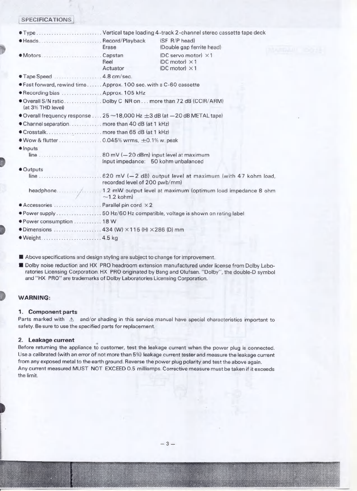
SPECIFICATIONS
ө
Type.
.
Vertical
tape
loading
4-track
2-channel
stereo
cassette
tape
deck
@Heads.
.
.
Record/Playback
(SF
В/Р
head)
Erase
(Double
gap
ferrite
head)
М
Capstan
(DC
servo
motor)
х1
Reel
(DC
motor)
x1
Actuator
(DC
motor)
x
1
©
Таре
Speed
.
4.8
cm/sec.
•
Fast
forward,
rewind
time
.
Approx.
100
sec.
with
a
C-60
cassette
e
Recording
bias
..
Approx.
105
kHz
e
Overall
S/N
ratio...............
Dolby
C
NR
on...
more
than
72 dB
(CCIR/ARM)
(at
3%
THD
level)
e
Overall
frequency
response
....
25
~18,000
Hz
+3
dB
(at
—20
dB
METAL
tape)
©
Channel
separation.
‚
more
than
40
dB
(at
1
kHz)
©
Crosstalk.
.
more
than
65 dB
(at
1
kHz)
eWowś.flutter.................
0.045%
wrms,
+0.1%
w.
peak
©
Inputs
ОРАО
ИЗВЕ
tees
80
mV
(—
20
dBm)
input
level
at
maximum
Input
impedance:
50
Корт
unbalanced
e
Outputs
Пе
рот
E
620
mV
(—2
dB)
output
level
at
maximum
(with
47
kohm
load,
recorded
level
of
200
pwb/mm)
ћеадрћопе........./........
1.2
mW
output
level
at
maximum
(optimum
load
impedance
8
ohm
—1.2
kohm)
9
Accessories
.
„Parallel
pin
cord
х2
e
Power
supply
.
50
Hz/60
Hz
compatible,
voltage
is
shown
on
rating
label
e
Power
consumption
.
.18
W
e
Dimensions
аи
а
лг
дал
434
(W)
x115
(Н)
x286
(D)
mm
eWejght
2202025330
4.5
kg
Ш
Above
specifications
and
design
styling
are
subject
to
change
for
improvement.
Wi
Dolby
noise
reduction
апа
HX
PRO
headroom
extension
manufactured
under
license
from
Dolby
Labo-
ratories
Licensing
Corporation.
НХ
PRO
originated
by
Bang
and
Olufsen.
"Роїбу",
the
double-D
symbol
and
“HX
PRO”
are
trademarks
of
Dolby
Laboratories
Licensing
Corporation.
WARNING:
1.
Component
parts
Parts
marked
with
A
and/or
shading
in
this
service
manual
have
special
characteristics
important
to
safety.
Be
sure
to
use
the
specified
parts
for
replacement.
2.
Leakage
current
2
Before
returning
the
appliance
to
customer,
test
the
leakage
current
when
the
power
plug
is
connected.
Use
a
calibrated
(with
an
error
of
not
more
than
5%)
leakage
current
tester
and
measure
the
leakage
current
from
any
exposed
metal
to
the
earth
ground.
Reverse
the
power
plug
polarity
and
test
the
above
again.
Any
current
measured
MUST
NOT
EXCEED
0.5
milliamps.
Corrective
measure
must
be
taken
if
it
exceeds
the
limit.
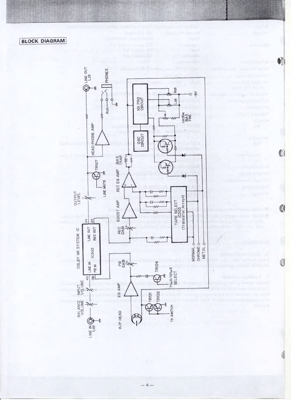
BLOCK
DIAGRAM
7
шпон
оча
XH
ѕэмона
|
|
.—o—
WU
шл
по
3NI1
w
ану
3NOHd
аузн
58
dW
ŁOLHL
6
ILAW
{SApJJY
2045150021)
—O
1vL3W
©
3WOYHO
O
TYWHON
HOLIMS
HL
Iv
оз
озн
айу
15008
$0651
103135
З4У1
123136
8"021/6"04.
РОШ.
му»
93H
ва
ану
o3
эчт
7
138431
1NdLno
9I
W3LSAS
YN
A8700
змолол
ам!
аузн
d/H
9%
5
шол
ov
Ta
NI
МІ
змолол
30NV
Iva
w
|
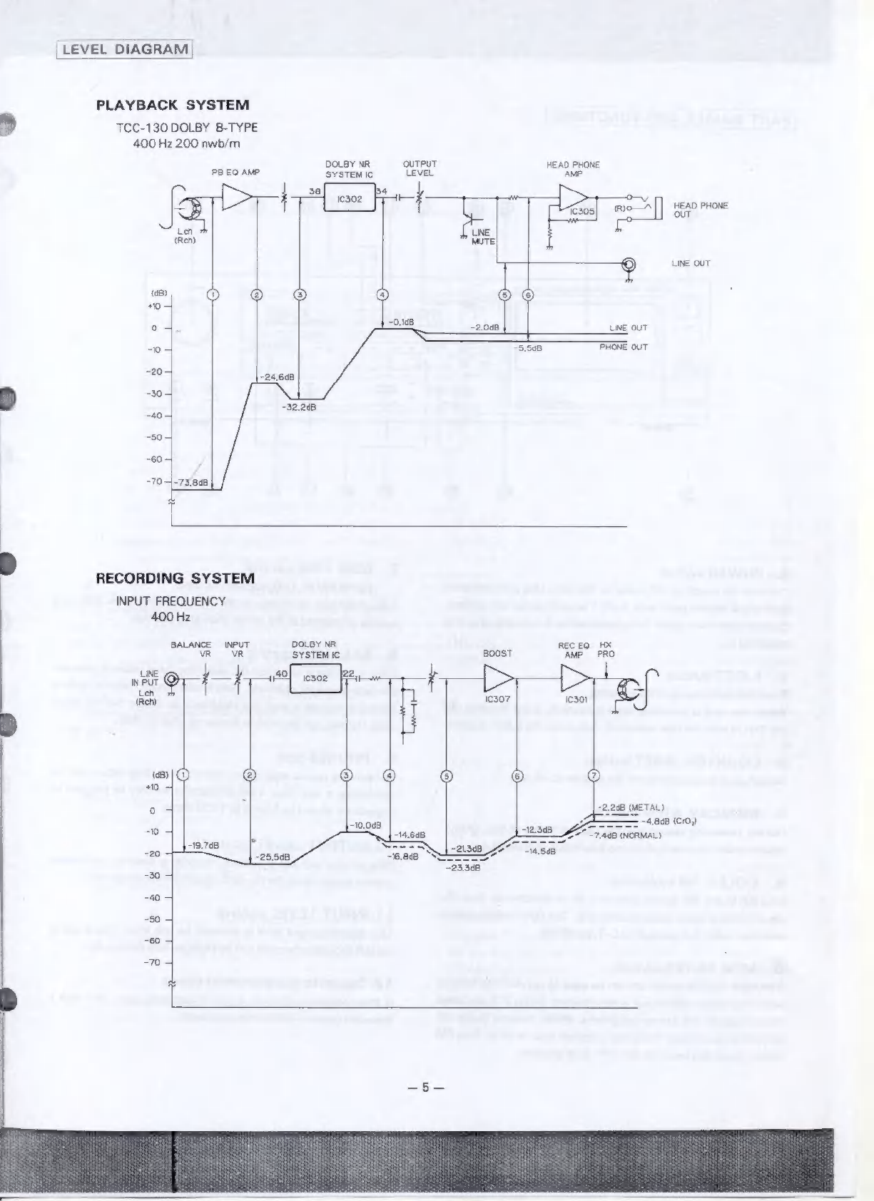
LEVEL
DIAGRAI
PLAYBACK
SYSTEM
TCC-130
DOLBY
B-TYPE
400
Hz
200
nwb/m
DOLBY
NR
OUTPUT
HEAD
PHONE
PB EQ
AMP
SYSTEM
IC
LEVEL
AMP
(>
>
i
38]
موم
Рр
|
RA
E,
зо]
me—^[]
HEAD
PHONE
Маш
LINE
LY
(Reh)
LINE
OUT
(dB)
0
чо
4
LINE
OUT
ost
PHONE
OUT
-204
5
-30-]
-40-]
-504
-60-1
-то-|
RECORDING
SYSTEM
INPUT
FREQUENCY
400
Hz
BALANCE
INPUT
DOLBY
NR
ВЕСЕО
HX
VR
VR
SYSTEM
С
BOOST
AMP
PRO
us
sof
ses
је
p
«ер
ро
Ef
dB
(METAL)
——
-4.86B
(Cro)
-о
4
T
:468
(NORMAL)
-ao
了
EM
-so
了
-во
4
-то
4
This manual suits for next models
1
Table of contents
Other Nippon Tape Deck manuals


