Nirax SPTC 400-110-10 User manual

Page 1 of 16
1.0 SAFETY INSTRUCTIONS
Important Safety Instructions
This manual contain important safety and operating instruction for Rectifier.
Model : SPTC 400-110-10.
1. Before using the Rectifier/Charger, read all instructions and cautionary marking for the
equipment.
2. DO NOT expose the Rectifier/Charger to rain or snow.
3. Use of an attachment not recommended or sold by the Rectifier/Charger manufacturer may
result in a risk of fire, electric shock or injury to persons.
4. DO NOT operate the Rectifier/Charger ; take it to a qualified service center when service or
repair is required. Incorrect assembly may result in a risk of electrical shock or fire. Unless
otherwise is instructed by the factory with a qualified service engineer.
Page 2 of 16
2.0 GENERAL INSTRUCTIONS
2.1 INTRODUCTION
Please read this manual thoroughly prior to use in order to become familiar with the unit’s features
and operating procedures. To obtain a maximum degree of safety, follow the prescribed sequences as
outlined.
This manual incorporates warnings and notes to the user. Points that are vital to the proper operations
or safety of the operators are indicated by the heading.
The Rectifier/Charger is designed to provide a fully regulated and constant DC Output Voltage from
AC Mains to the DC load or Electrical Equipment.
The complete DC system consist of 2 unit of SPTC 400-110-10 & Battery Banks. The unit, SPTC
400-110-10, is connected in parallel to charge the Battery Banks and supply power to the equipment
under normal operating mode.
Upon power failure, the battery will take over to supply the loads without any interruptions. The
backup time is depending on the battery sizing and its capacity.
2.2 TECHNICAL SPECIFICATION FOR RECTIFIER/CHARGER
AC INPUT :
Voltage System Input 400VAC, Three Phase , 4 Wire
Frequency 50Hz
DC OUTPUT SPTC 400-110-10
Voltage 110VDC nominal
Current 10 Amps DC nominal
Power 1100 Watt
Voltage Range 98.5 – 121.5 VDC
Voltage Tolerance Less than 1%
Characteristic Constant Voltage with Current Limiting

Page 3 of 16
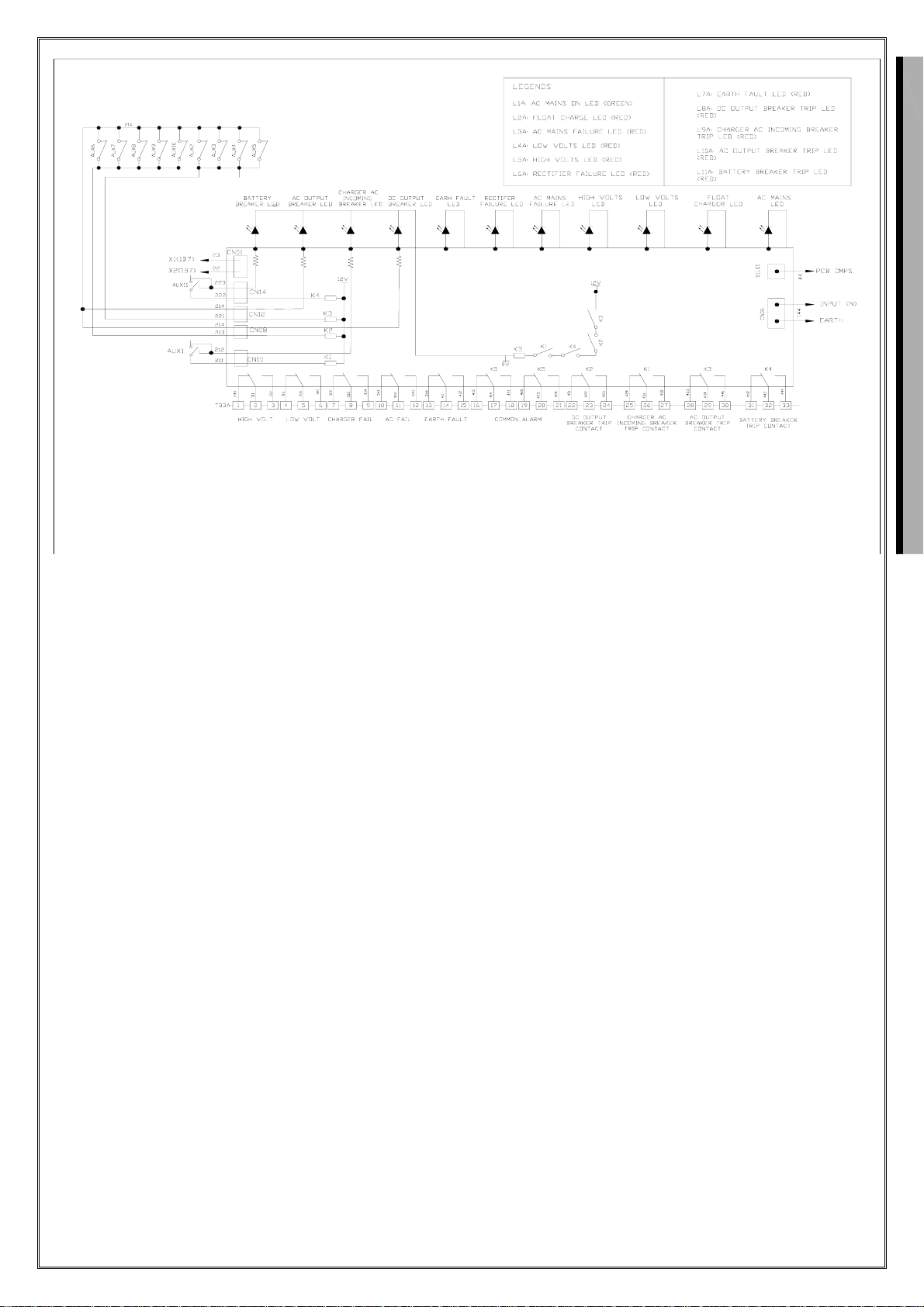
Indications AC Main On Led (Green)
Float Charge Led (Red)
Low Volts Led (Red)
High Volts Led (Red)
AC Main Failure Led (Red)
Rectifier Failure Led (Red)
Earth Fault Led (Red)
DC Output Breaker Led (Red)
Charger AC Incoming Led (Red)
AC Output Breaker Led (Red)
Battery Breaker Led (Red)
Alarm AC Main On
Rectifier Failure
High Volts
Low Volts
Earth Fault
DC Output Breaker
AC Input Breaker
AC Output Breaker
Battery Breaker
Common 1
Common 2
Protection DC Output Breaker
AC Input Breaker
AC Output Breaker
Battery Breaker
Current Limit Protection
Cabinet Protection Class IP31
Finishing Epoxy Power Coating
Cabinet Mounting Floor Mounting Type
Cable Entrance Bottom Entrance
MISCELLANEOUS :
Accoustic Noise Less than 54dBA at three feet
Cabinet Size H x W x D = 1190 x 500 x 400 mm
Weight Approx. 100 Kg
Ambient Temperature 25-65 degree C

ENVIRONMENTAL
Temperature 0 - 65 degree C (Operating)
-20 to +60 Degree C (Storage)
Humidity 0 - 95 % Non-Condensing
Elevation 500m below to 2800m above sea level
Warning :
Confirm that the battery and load current polarity connection is correct to prevent damage to the
load to the Rectifier/charger.
2.3 OUTPUT DC VOLTAGE AND OUTPUT DC CURRENT LIMIT ADJUSTMENT
To adjust the output dc voltage, trim the VR01 at PCB control modul (CMPS-06T1)
Output dc current limit, trim the VR02 at PCB control modul (CPMS-06T1)
3.0 CIRCUIT CONFIGURATION
3.1 CURRENT PATHS DIAGRAM
(Refer to Single Line Diagram)
1. The unit is controlled by the input breakers. Rectifier units can be connected in parallel with
battery to form a DC power supply system.
2. Under normal condition, the Rectifier input breakers are closed and the AC power is converted
into DC power to charge the batteries as well as supply power to the equipment.
3. In the event of AC power failure, the battery will supply all loads without any interruption.
Page 4 of 16
CMPS-06T1
Current float adjust
Float voltage adjust
SIL02
SIL03
VR101
CN04
CN03
VR02
VR01 CN01
CN02
SIL01
PCB
VR102
Forsensor output
dc Voltage low adjust Forsensor output
dcVoltage high adjust
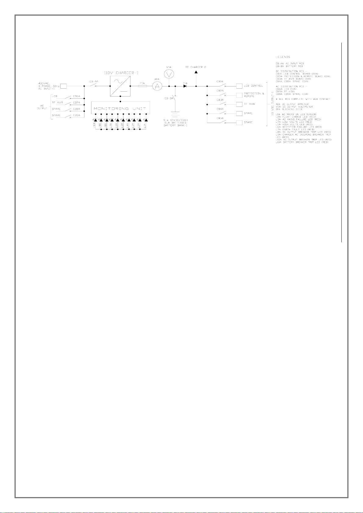
3.2 SINGLE LINE DIAGRAM
3.3 FEATURES OUTLINES DESCRIPTIONS
The following are the description of the major components for the power supply system.
Input Breaker To switch on the input supply to the unit as well as to provide over
current protection upon any failure of the units.
Ouput Breaker a. To switch on the output supply from the unit as well as to
provide over current protection upon any failure of the unit.
b. To provide control and short protected for the Load Circuit.
Battery Breaker
To provide over load protection when charging of battery and
discharge to the load as well as provide isolation for maintenance.
Alarm Contact
Relay dry contact output for remote monitoring of AC input voltage
,Rectfier failure , High Volts , Low Volts , Earth Fault , DC Ouput
Breaker , AC Input Breaker , AC Output Breaker , Battery Breaker
Page 5 of 16

3.4 SCHEMATIC DIAGRAM
Page 6 of 16
3.5 Rectifier Specifications
Page 7 of 16

Page 8 of 16
The following specifications are tested under the conditions of AC 400V/50Hz Three phase and 25°C
ambient temperature besides additional declarations.
AC Input
Input Voltage Range 380 – 410V
Phase 3 Phase
Frequency Range 50Hz
Efficiency > 80% (> 50% Load)
Protections Input Breaker
Ouput AC Breaker
Ouput DC Breaker
Over Current Protection
Surge Protections
DC Output
Output Power 1100W max
Output Voltage 110V (Float Charge Mode)
Output Current 10A (typical)
Load Regulation ± 1% of output voltage setting
Line Regulation ± 0.5% of output voltage setting
Stability ± 1% of output voltage setting
Soft start Time < 5 seconds
4.0 INSTALLATION INSTRUMENTS

Page 9 of 16
4.1 SAFETY PRECAUTION
1. DOT NOT expose the Rectifier/ Charger to rain or snow or below air-condition unit.
2. DOT NOT operate the Rectifier/ Charger of it received a sharp blow, being dropped or
otherwise damaged in any way; take it to a qualified service center.
3. Before any connection, read marking on all terminal blocks with reference to the Schematic
diagram.
4.2 INSPECTION
All Rectifier products are shipped in rugged, wooden crated and “foamed in place” to minimize shock
that may occur during transportation.
Prior to uncrating, note any damaged to the shipping container. Uncrate the Rectifier and inspect the
exterior. If any damage is observed, contact the carrier immediately.
4.3 PREPARATION/MOUNTING
The Rectifier/ Charger unit has been designed for floor mounting or floor standing type or cubicle.
The unit must be mounted in a clean and dry environment sufficient access to an uninterrupted air
source must be provided in the surrounding area of the unit.
Allow at least 200mm on the side of the unit for ease of airflow.
The AC input and DC output cable entry is at the bottom of the unit.
The battery cable entry is at the bottom of unit.
4.4 INPUT CONNECTION
WARNING
The input breaker must be in the “OFF” position before attempting to install the Rectifier/Charger.
1. The Rectifier/Charger shall only be connected with input voltage of 400VAC, 3 Phase, 50Hz.
Confirm the operating voltage before proceeding.
2. Input wires can be routed through the cable entry hole at the bottom of the cabinet.
3. Input cable for Rectifier/Charger shall be connected to Terminal Block marks “R” (Red), “Y”
(Yellow), “B” (Blue), and “N” (Neutral).
WARNING
Ensure that the input and output breakers are in “OFF” position prior to any work being performed
on the AC and DC connections.
4.5 OUTPUT CONNECTION
WARNING :

Ensure that all Output Loads Breaker and Battery Breaker are in “OFF” position before attempting
work on the output cable assembly.
1 The DC Load Breakers (for equipment) are provided for this system output.
2. The DC Output Cable shall be at least 2mm sq. per 10A outlet for equipment DC Output. The
breaker is rated at 10A.
3. The Positive Load Cables shall be connected to the Load Positive Terminal and the Negative
Load Cables shall be connected to the Load Negative Terminal.
4. Connect the 9 block (12V per block) of batteries in the series to form 108V Battery Bank.
5. Connect the Battery Positive Terminal and Battery Negative Terminal to Battery Bank. Ensure
the polarity is correct.
WARNING :
Observe the correct polarity of the output cable when terminating.
5.0 TERMINAL BLOCK ARRANGEMENT DIAGRAM
Page 10 of 16
LNLNLNLN RYBN
A
C OUTPUT AC INPUT
LCB
CONTROL TF AVR SPARE SPARE
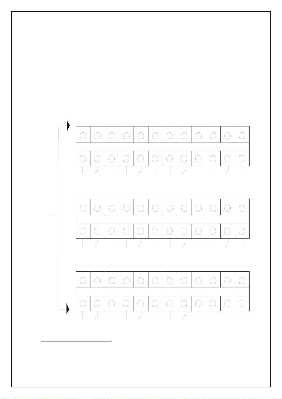
ALARM
CONTACT
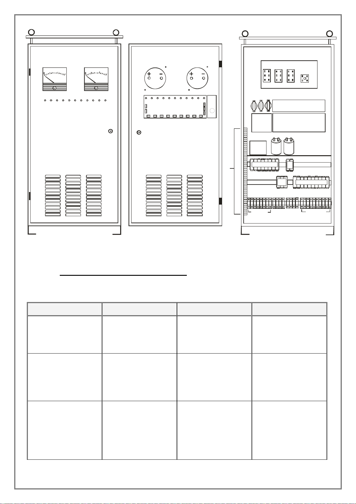
6.0 CABINET DIMENSION
FRONT VIEW BEHIND THE PANEL DOOR IN SIDE VIEW
Page 11 of 16
123456789
10 11 12
AC MAINS RECTIFER
FAILUR
E
HIGH VOLTS LOW VOLTS
123456789
10 11 12
EARTH FAULT DC OUTPUT
BREAK
DC INTPUT
BREAK
AC OUTPUT
BREAK
123456789
10 11 12
BATTERY
BREAK
COMMON 1 COMMON 2
7.0 SYSTEM TROUBLE SHOOTING
Diagnostic - general
Operating Condition Symptoms Possible Causes Remedy
Input Breaker ON, no
DC Output Voltage.
AC Main Failure Led
ON
Rectifier failure led on
No mains supply.
Rectifier faulty.
Turn On mains supply.
Replace Rectifier.
400V Input Voltage
available.
AC Input MCB always
trip off and cannot be
reset.
Faulty MCB.
Faulty Rectifier
Replace Breaker.
Replace Rectifier
System function
normal during AC
input ON.
System shut down
during AC failure.
Battery Breaker open
Faulty Battery cable or
connection.
Faulty Battery.
Replace Breaker
Check cable and
connection
Replace Battery
Page 12 of 16
DC OUTPUT VOLT METER
DC O U TP UT A M M ETE R
50 100 150
V
510 15
A
T
E
R
M
I
N
A
L
B
L
O
K
PCB CLPS
PCB DMPS
PCB
CH G 1A CC
POWER MODUL
TRAFO
TERMINAL BLOK
CMPS
R
M
A
L
A
PCB IDPS
FUS E D C
OUTPUT
AC OUTPUT IN PUT
BATT TO
CH ARG ER 2
DC OUTPUT
MCB DC OUTPUT
MCB
INPUT
MCB AC OUTPUT
MCB
BATT

Page 13 of 16
Input Breaker is ON.
No DC supply to
equipment.
Load Breaker Open.
Load Cable Open.
ON the Breaker
Check load wires for
loose connection.
110V System function
normal.
Received Low Voltage
Alarm Failure or AC
Failure Alarm.
Input AC Voltage not
stable.
Consult Building M &
E staff.
7.0 MAINTENANCE PROCEDURE
8.1 Maintenance Procedures For Charger System
1. Record the data on the Monthly Maintenance Record Sheet monthly.
Description
Criteria
Result
Remarks
Confirm AC Input Voltage
400VAC +/- 10%
Confirm DC Output Voltage
110VDC +/- 1%
Confirm and Record DC Output
Current
10 ADC Max.
Confirm and Record Alarm
functional
Check the alarm status
Note: Please consult the factory for advice if the result is not within Specified Criteria
2. Check the tightness of the Terminal Points at the output of the system
3. Perform General Cleaning on the Cabinet half yearly. Ensure that the air flow is not blocked by
the Dust at the front and rear side of the Cabinet.
4. Test the module separately or individual and see the function.
5. Perform the Alarm Functional Check. Record the Remote Alarm Status.
6. In order to check the status of the battery, off the system to let the battery discharge for 5 min.
Ensure the battery bank did take over to supply power to the customer equipment and record the
system Battery Total Voltage (After 5 minutes with load connected). This data shall be check
with previous monthly record. Consult factory for advise the if the different in reading are greater
than 5%.
7. Power On the Charger System.
8.2 Battery Maintenance Procedures
The following checks should be completed quarterly.

Page 14 of 16
1. Visually inspect the battery for :
- Cleanliness
- Terminal Damage or Evidence of Heating.
- Container or Cover Damage
- Evidence of Overheating
- Grease on the battery terminals
2. Measure and record the Battery system DC boost and float charging voltage at the battery.
3. Measure and record the individual unit DC boost and float charging voltage.
4. If possible, measure and record the battery system DC and AC boost and float charging current.
8.0 TRANSPORTATION & STORAGE
Units must be suitable packed in the original shipping container (or equivalent) prior to reshipping.
The box should completely enclosed and constructed of wood.
Units must be stored in a dry environment.
DOT NOT stack heavy objects on top of the unit.
Contents
1). Safety Instructions ……………………………………………………………………………… 1
2). General Instruction
2.1). Introduction …………………………………………………………………………… 2
2.2). Technical Specification for Rectifier/Charger ....................................................... 2

Page 15 of 16
2.3). Output DC Voltage and Output DC Current Limit Adjustment ……………………….. 4
3). Circuit Configuration
3.1). Current Paths Diagram ………………………………………………………………. 4
3.2). Single Line Diagram …………………………………………………………………. 5
3.3). Features Outlines Descriptions ………………………………………………………. 5
3.4). Schematic Diagram …………………………………………………………………. 6
3.5). Rectifier Specifications ……………………………………………………………….. 8
4). Installation Instrument
4.1). Safety Precaution ……………………………………………………………………. 9
4.2). Inspection ……………………………………………………………………………. 9
4.3). Preparation/Mounting ……………………………………………………………….. 9
4.4). Input Connection …………………….………………………………………………. 9
4.5). Output Conection ……………………………………………………………………. 10
5). Terminal Block Arrangement Diagram ……………………………………………………… 11
6). Cabinet Dimension …………………………………………………………………………... 12
7). System Trouble Shooting ……………………………………………………………………. 12
8). Maintenance Procedure
8.1). Maintenance Procedure For Charger System .………………………………………. 13
8.2). Battery Maintenance Procedure …………………………………………………….. 14
9). Transportation & Storage ……………………………………………………………………. 14
OPERATIONAL AND INSTRUCTION

Page 16 of 16
MANUAL
RECTIFIER SYSTEM
SPTC 400-110-10
Table of contents


