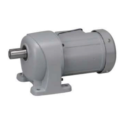
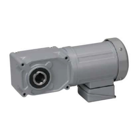
Nissei F2 Series User manual

SmallSize/
SmallWater-resistantGearmotor
15W■25W■40W■60W■90W
InstructionManual
ForSafeOperation
●TheGearmotorshouldbeoperatedbyaskilledandqualifiedperson.Andthe
contentsofthisInstructionManualshouldbecarefullyreadandunderstood
beforeoperatingthisproduct.
●ThisInstructionManualshouldbedeliveredtoapersonwhoactually
operatesthisproduct.
●ThisInstructionManualshouldcarefullybekeptinaconvenientplaceforthe
operator'seasyreference.
≪F2Series≫
≪H-Type・Water-resistant≫
≪GT-Type≫
≪G-type・Water-resistant≫
≪F2Series・Water-resistant≫
≪G-Type≫
≪H-Type≫
Manufacturer NISSEICORPORATION
Address 1‐1InoueIzumi‐choAnjo‐shi,Aichi,444‐1297JAPAN
TEL +81‐566‐92‐5262
FAX +81‐566‐92‐1159
ONLINESPAREPART

2
Thankyouforyourpurchasingourproduct.
Danger
Caution
Danger
●Besuretouseanexplosion-proofmotorwhereanyexplosiveorflammablegases
exist.Failuretoobservethiswarningmaycauseexplosion,spark,fire,electric
shock,physicalinjury,and/ordamagetotheequipment.
●Theoperatorsinchargeoftransportation,installation,wiring,operation,
maintenance,andinspectionoftheequipmentshouldhaveenoughknowledgeand
technicalskillfortheproduct.Failuretoobservethiswarningmaycauseexplosion,
spark,fire,electricshock,physicalinjury,and/ordamagetotheequipment.
●Donotrepairorwiretheequipmentwiththeelectricpoweron.besuretocutthe
poweroffthepowersupplybeforegettingtowork.Failuretoobservethiswarning
maycauseelectricshock.
●Iftheequipmentistobeusedinasystemforhumantransport,besuretofurnishit
withaprotectivedeviceforsafety.Failuretoobservethiswarningmaycause
physicalinjuryand/ordamagetotheequipmentbyaccidentalfalling.
●Iftheequipmentistobeusedwithanelevator,besuretofurnishwithasafety
devicetopreventtheelevatorfromaccidentalfalling.Failuretoobservethiswarning
maycausephysicalinjuryand/ordamagetotheequipment.
●Besurenottogetwateroroil/greaseintothebrakeunitFailuretoobservethis
warningmaycauseaccidentalfallingand/orrunawayaccidentbythedecreased
braketorque.(Incaseofwater-resistanttype,atthetimeofadjustingbrakegap)
InthisManual,injuriesanddamagesanticipatedincaseofmishandlingoftheequipment,
areclassifiedintotwocategories,"Danger"and"Caution".Thedefinitionofthe
classificationaregivenbelowwiththecorrespondinggraphicsymbols.
Thecasethatmishandlingoftheequipmentmay
resultindangeroussituationandmayleadto
seriousorfatalinjurytopersonnel.
Thecasethatmishandlingoftheequipmentmay
resultindangeroussituationandmayleadto
mediumtolightinjury,orthecasethatmayresultin
damagetotheequipment.
Pleasebeawarethatevenitemsmarkedwith"CAUTION"maycausefatalaccidents.
Therefore,besuretofollowtheinstruction,foreveryitemdescribedisveryimportant.
ONLINESPAREPART

3
Caution
1
2
3
4
5
6
7
Checkattheunpacking
Transportation
Storage
Installation
ConnectingwithOtherEquipment
DirectionofRotation
Wiring
……P.3
P.4
P.4
P.5
P.6
P.8
P.8
………
……………
……………
…
…
…………………
8
9
10
11
12
13
Operation
InspectionandAdjustment
Troubleshooting
Disposal
Appendix(GearmotorcertifiedbyT¨
UV)
Warranty
…………P.17
P.19
P.23
P.24
P.25
P.27
…
…
……………
…
……………
Contents
1 Checkattheunpacking
Caution
●Donotuseagearmotorunderconditionsotherthanspecifiedinthenameplateorthe
productspecifications.Failuretoobservethiswarningmaycauseelectricshock,
physicalinjuryand/ordamagetotheequipment.
●Donotinsertyourfingersoranyotherobjectintotheapertureofthegearmotor.
Failuretoobservethiswarningmayresultinelectricshock,physicalinjury,fire
and/ordamagetotheequipment.
●Donotusethedamagedgearmotor.Failuretoobservethiswarningmayresultin
physicalinjuryand/orfire.
●Donottakeoffthenameplate.
●Themanufacturerwillnotwarrantandwillnotresponsiblefortheproductmodifiedor
repairedbytheuserhimself.
Whenunpackingacarton,pleasecheckupthefollowings.Ifyouhaveanyproblemsor
questions,pleasedonothesitatetocontactthedealerfromwhichtheproductwas
suppliedorasalesoffice.
Checkwhethertheproductisthesameproductasordered.Installingawrong
equipmentmaycausephysicalinjuryand/ordamagetotheequipment.
(1)Theorderedproductsandthecontentsindicatedinthenameplatearecorrect.(Type,
Reductionratio,Motorcapacity,Voltage,Frequency,etc.)
(2)Noaccidentaldamagetotheproductduringtransportationexist.
(3)Screwsornutsarenotloose.
(4)Incaseofgearmotorattachedwithbrake,rectifierisenclosed.
(Notnecessaryincaseofgearmotorwithbuilt-inrectifierattachedwithterminalbox.)
(5)In case of gearmotor with clutch/brake, one rectifier and two surge
suppressorareenclosed.
(6)Incaseofsingle-phasemotor,capacitorisenclosed.
(7)IncaseofF2series,saftycapisenclosed.
ONLINESPAREPART

4
2 Transportation
Danger
Caution
3 Storage
●Whenaproductisliftedupfortransportation,besurenottoenterunderneathofthe
liftedproduct.Fallingofproductmaycauseseriousinjury.
●Becarefulwhentransportingproductstoavoidfallingdown.
●Before lifting the gearmotor up, be sure to confirm its weight by nameplate,
packingbox,externalconfiguration,catalogue,etc.Donotliftupgearmotorwhich
hasmoreweightthantheonespecifiedinthelift.Failuretoobservethiswarning
maycausephysicalinjurybybreakingofbolt,fallingortumblingofproduct,and/or
damagetotheequipment.
●Locationforstorage
In case of storing gearmotors for more than 6 months, be sure to store them
indoorswellventilated and dry, free from directsunlight,excessivetemperature
change,humidity,dustandcorrosivegas.
(1)Besurenottoputgearmotorsdirectlyontheground.
Bearings may be damaged by fretting corrosion caused by vibrations during
storage,thereforebesuretostoregearmotorsinthelocationfreefromvibration.
●Dutiesduringstorage
(1)Inordertoavoidanyoxidizationonbearings,besuretogiveatrialrunevery6
monthtoconfirmiftheyrotatesmoothlyorifthereisanyabnormalnoise.
(2) Be sure to measure the insulating-resistance by 500V tester(megger) every 6
monthtomakesureifitshowsmorethan1MΩ.
(3) Be sure to provide anticorrosive treatment every 6 month on the machined
surfacesuchasoutputshaftandflangesurfacenotpainted.
●Operationsjustafterstorage
(1) Before operation, be sure to measure the insulating-resistance by 500V tester
(megger)tomakesureifitshowsmorethan1MΩ.
(2)Checkifthereisanyabnormalnoise,vibrationortemperatureriseatthestartof
operation.
(3)Incaseofgearmotorwithbrake,besuretoconfirmifthebrakefunctionsproperly.
Inanyabnormality,pleasecontactourofficenearesttoyou.
ONLINESPAREPART

Caution
4 Installation
●Do not place any object inflammable near the gearmotor. Failure to observe this
warningmaycausefire.
●Do not place any object which may interfere with the ventilation around the
gearmotor. Failure to observe this warning may result in abnormal overheating
causedbytheblockoffofthecoolair,whichmaycauseburninjuryand/orfire.
●Donotsteponagearmotororhangtoit.Failuretoobservethiswarningmaycause
physicalinjury.
●Donottouchtheedgeoftheshaftofgearmotororkeygrooveintheborewithbare
hands.Failuretoobservethiswarningmaycausephysicalinjury.
●Inequipmentslikefoodmachines,whichmustavoidoilorgrease,furnishwithprotective
deviceslikeoilpan,inordertoprotectfromtheoilleakagecausedbyfailureorlifeofthe
manufacturedproducts.Leakingoilmaycausedefectiveproducts.
●Thereispossibilityscattertheweardebrisorironpowders.
Incaseofinstallingtoequipmentwhichwillhaveanyissueduetocontaminationof
foreign substance such as food equipment, please install preventive equipment.
Thiscouldharmtheproducts.
●Vibrationscomeoutfromtheinstallationsurfaceofgearmotororfromothersource
shouldbeminimizedtounderabout0.5G.
●Inthehotandhumidenvironment,whenambienttemperaturechangessuddenly,
internal condensation may occur in the terminal box. Especially, in the ocean
transportofthemachinebyvessel,condensationmayoccur,therefore,paycareful
attentiontothetransportatmosphere.Internalcondensationisaphenomenonthat
inthehotandhumidenvironment,iftemperaturesuddenlydropsfromhightolow,
or if a reducer is suddenly moved from low-temperature place to hot and humid
place,steamcondensationoccursandthedropletlandontheterminal.
●In the low temperature of below 0℃, pay careful attention to the freezing. The
droplets land on the terminal by condensation or by abnormally high humidity
atmospheres, and when temperature drops below freezing point, the droplets
becomeice.ThisiswhatwecallFreezing.Youmustnotethatthereisadanger
ofelectrificationcausedbytheshortcircuitbetweenterminalsbyfreezing.
Properinstallationofaproductwillensurereliableserviceandmaximumlife.
5
ONLINESPAREPART

6
(1) Properlocationforinstallation
AmbientTemperature:−10℃to40℃
AmbientHumidity:85%max.
Altitude:Sealevelto1,000mmax.
Environment:
[StandardType]:Wellventilatedplacefreefromcorrosivegas,
explosivegas,vaporand/ordust.
[Water-resistantType]:Placefreefromcorrosivegasandexplosivegas.
Operationinwaterorinthehigh-hydrostaticpressure
environmentisnotpermitted.
InstallationLocation:Indoors
(2) DirectionofInstallation
Thisproductcanbeinstalledinanydirectionduetoagreaselubricationsystem.
(3) MethodforInstallation
①Attachingthemountingfootandflange
Fixtheproductwiththefourboltsonaflatandmachinedsurfacefreefromvibration.
(Roughnessofthesurfaceshouldbelessthan0.3mm.)
②Attachingtheshaft
●gearmotor'sweightshouldbesupported
bythedrivenshaft.
(Forcesotherthanturningreactiveforce
shouldneverbeimposedtothetorquearm.)
●Incasestart/stopandforward/reverseactions
arefrequent,tightnupthetorquearmwith
boltstokeepthelockingholenotloose.
tighteningtorqueboltsizefixinghole
4.9N・m
{ 0.5kgf・m}
13 { 1.3}
25 { 2.6}
44 { 4.5}
69 { 7.0}
108 {11.0}
M6
M8
M10
M12
M14
M16
6.5m m
8.5
11
13
15
18
5 Connectingwithotherequipment
Caution
●Whenconnectingthegearmotorwithaload,makesureofthealignmentofshaft,the
tension of the belt and parallelism of pulleys. In direct coupling, be sure to check
whetherthealignmentofshaftisextremelyprecise.
Ifabeltistobeused,besuretoadjustitstensionproperly.
Also,beforeoperation,inspectwhetherthesettingboltsforpulleysandcouplingare
securelytightened.Failuretoobservethiswarningmaycauseseriousinjury and/or
damagetotheequipmentduetobrokenparts.
●Safeguardsshouldbefurnishedaroundrotatingpartstoavoiddangertopersons.
Loosefitisrecommendedforthecouplerssuchascouplings,sprockets,pulleys,gears,
etc.,whenattachingtothereducer,usingthedesignatedkeymaterials.
ONLINESPAREPART

1 DirectConnection
2 AttachingChains,V-Belts,Gears,etc.
3 AttachingandRemovingofF2SeriesHollowShaft
①AttachingtoHollowShaft ②RemovingfromHollowShaft
③FixingtoHollowShaft
○
a
Incasethedrivenshafthasashoulder
○bIncaseofnoshoulderonthedrivenshaft
Note:Firmlyfixthedrivenshafttothehollowshaft.
Note:Inorderforsmoothremoving,designthedrivenshaftshorter
withthelengthequaltotheamountofthethicknessof○
c.
●Specificationsforthefixingpartsofdrivenshaft
Nominal
Designation
oftheC-Type
SnapRing
MeasurementofSpacer
Bolt
Size WidthBore
Outer
Diameter
Note:
1) At attaching, apply agent such as molybdenum disulfide on the
drivenshaftandtheboreofthehollowshafttoavoidseizing.
2)Incasethefittingistootight,taptheedgeofthehollowdriveshaft
with wooden hummer. With this device, smooth insert can be
obtained.
3)Theboreofthehollowshaftismachinedtoconform to"JISH8"
tolerance.Ifstrongimpactorheavyradialloadis tobeimposed
to the shaft, the fit should be tighter. In general, loose fit is
recommendedforthefittoleranceofdrivenshaft
4) The key should be conformed toJIS B 1301-1976or
equivalent. Refer to the JIS standard B 1301-1976 for the
details.
Connectthereducertotheotherequipmentprecisely,sothatthecenteroftheshaftof
bothmachineswillbefullyaligned.
(1)Inanyconnection,connecttheunitsprecisely,sothatthecenteroftheshaftofthe
reducerandthatoftheotherequipmentareparallel.
(2)ThetensionoftheChains/V-Beltsandthecouplingofthegearmustbeperpendicular
tothecenteroftheshaft.
(3)TensionoftheV-Belt:Excessivetensioningmayresultindamagetothebearingsoftheshaft.
TensionoftheChain:Excessivetensioningmayresultindamagetothebearingsof
theshaft.Ifthechainisinstalledloosely,shockloadwilloccurwhenthedriveshaft
startsrotation,andthiscanresultindamagetothereducerandtheotherequipment.
Therefore,adjustthetensionofthechainproperly.
cross-sectionof
inthedrawing
○
c
123 611.5M5F2S −12
153 714.5M6F2S −15
7
ONLINESPAREPART

6 DirectionofRotation
Caution
IntheGTRReducer,therelationsbetweentheinputshaftandtheoutputshaftareas
shownbelow:
●G-Type
1/5〜1/60samedirection 1/80〜1/1800counterdirection
●H-Type
15W・25W 1/10〜1/60And1/300〜1/1800
40W・60W 1/10〜1/60And1/300〜1/900
90W 1/10〜1/60And1/300〜1/450
●F2Series
1/5〜1/60
15W・25W 1/80〜1/240
40W・60W
1/80〜1/240
And
1/1200〜1/1800
90W
1/80〜1/240And1/600〜1/1800
●G-Type
15W・25W 1/5〜1/25 samedirection 1/30〜1/200 counterdirection
40W 1/5〜1/30 samedirection 1/40〜1/200 counterdirection
60W 1/5〜1/15 samedirection 1/20〜1/120 counterdirection
7 Wiring
Danger
●Whenconnectingthemachinetothepowercable,besuretofollowtheinstructions
shownintheconnectiondiagramintheterminalboxorintheInstructionManual.
Failuretoobservethiswarningmaycauseelectricshockorfire.(Incaseofthetype
ofnoterminalbox,besuretoinsulateawireattheterminalarea.)
●Donotbend,pullortuckdownpowercables,motorleadwiresorcabtirecable
forcibly.Failuretoobservethiswarningmaycauseelectricshock.
●Besuretogroundtheterminaloftheearthwire.Failuretoobservethiswarningmay
causeelectricshock.
●Besuretousetheelectriccurrentsourcespecifiedinthenameplate.Failureto
observethiswarningmaycauseburnoutofthemotorand/orfire.
●Donotdamagetheleadwireinsidewhenpeelingofftheoutersheathofcabtyre
cable.Failuretoobservethiswarningmaycauseelectricshockorfire.
●Besuretoavoidanywatertotheterminalorpowerrectifierofcabtyrecableor
capacitor.Failuretoobservethiswarningmaycauseelectricshock,damagetothe
equipmentorfire.
[Note]Donotopenthecoverofthewateranddust-resistantbox.
Failuretoobservethiswarningmaycauseelectricshock,damagetotheequipmentor
firecausedbylackofwateranddust-resistantfunction.
Beforecouplingwiththeothermachine,besuretocheckthedirectionofrotation.Unexpected
operationinwrongdirectionmaycauseseriousinjuryand/ordamagetotheequipment.
1/80〜1/240
8
ONLINESPAREPART

Caution
●Donottouchterminalswheninspectingtheinsulationresistance.
Failuretoobservethiswarningmaycauseelectricshock.
●Wiringshouldbeproperlymadeunderthespecifiedelectricalequipmentengineering
standardorthesafetycode.Failuretoobservethiswarningmaycauseelectricshock,fireor
physicalinjury.
●Ourmotorisnotequippedwithprotectivedevices.Theelectricalequipmentengineering
standardsprovidethatanoverloadprotectiondeviceshouldbeinstalledinaunit.Other
protectiondevicessuchascircuitbreakerarealsorecommendedtobeinstalled.Failureto
observethiswarningmaycausedamagetotheequipment,electricshock,fireorphysicalinjury.
●Whenrotatinggearmotoralone,takeoffthekeyattachedtemporarilytotheoutputshaft.
Failuretoobservethiswarningmaycausephysicalinjury.
●Checkupthedirectionofrotationbeforeconnectingwiththeothermachine.Rotationinwrong
directionmaycausephysicalinjuryand/ordamagetotheequipment.
●Ifa400Vclassinverterisemployedformotordrive,besuretoattachacontrolfilterorareactor
totheinverter.Thebreakdownofinsulationmaycausedamagetotheequipmentorfire.
●Donotmisuseacapacitorforstartingastheoneforcontinuousmotorrunning.Thismisuse
maycausedamagetothecapacitor.
●Donothurtthevinylcoatingofstartercapacitor.Thehurtmaycauseelectricshock.
●Voltagedropsinthewiringshouldbekeptwithin2%.Excessivelengthofwiringmaycause
steepvoltagedropandthismakesthemotordisabletostartup.
●Whenreversingagearmotorisrequiredinoperation,besuretostoprotatingandthenstart
reversing.Reversingwithoutcompleterestmaycausedamagetotheequipment.
●Asforagearmotorwithbrake,donotenergizecontinuouslytothebrakeunitduringtherestof
motor.Thecontinuoussupplymaycauseburningofthebrakecoilandfire.
●Ifagearmotorwithbrakeisusedfortheapplicationsuchaslift,"DCSwitching"wiringshould
beemployedtoavoidaccidentalfalling.
(1)Astherectifierunitcontainsdiodes,improperwiringmaycausefatalshort-circuiting
andbreakageoftheunit.So,specialcareshouldbetakenforwiring.
(2)IncaseofDCswitchisadopted,DC110V,contactratedDC13classisrecommended
inordertocutofftheinductiveload(DCcoil).Pleasecontactusfordetails.
Also,incaseofemployinganoncontactrelay,itisrecommendedtousetherated
voltageofAC240Vequivalent(Half-waverectificationswitchingavailable).
*ContactratedDC13classisthecategorizedinJISC8201-5-1forlow-pressure
switchgearandcontroldevice.
(3)Incaseofgearmotorwithclutch/brakeusetherelaywiththecapacityofmorethantherated
currentof1A(DC110V)atthecontactpointofbrakeandclutch.
(4)Thedirectionofrotationoftheoutputshaftvariesaccordingtothespeedreduction
ratioofthegearhead.Therefore,besuretoconfirmthespeedreductionratiobefore
wiring.
(5)Thevoltagebetweenthecapacitorterminalsofthesingle-phasemotorwillbecomenearlytwice
asmuchasthatinthepowersourceofthemotor.Thereforebesuretoinsulatewiresatthe
terminalsforsafety.
9
ONLINESPAREPART

2 Wiringofgearmotor
●LeadWireType
200V
100V
400V
3-Phasemotor Single-phase
200V
●TerminalBoxType
Single-Phase100V,200V3-Phase200V,400V
MS:Electro-MagneticSwitchC:Capacitor
MS:Electro-MagneticSwitchC:Capacitor
R
Motor
S
T
Fwd
Rev
Power
source
gray
black
white
R
Motor
S
T
black
brown
white
Fwd
Rev
Power
source
Motor
C
blue
black
gray
Fwd
Rev
Power
source
Power
source
MS
Motor
C
brown
black
gray
Fwd
Rev
MS
R
S
T
Fwd
Rev
W
V
U
C
1
2
3
Rev
Fwd
MS
Forstandardgearmotors,wiringsdescribedbelowarerecommended:
Thedirectionofrotationshownbelowisasviewedfromthebackwardofthemotor.Inthe3-phase
motor,theforwardrotationisacounterclockwisedirection,andinthesingle-phasemotor,theforward
rotationisaclockwisedirection.
Power
source
Power
source
10
ONLINESPAREPART

3
Wiringforgearmotorwithbrake
0.005〜0.015DCSwitching
0.03〜0.10ACSwitching(A)
0.1〜0.2ACSwitching(B)
■3-phase
(1)Ifagearmotorisusedintheapplicationswherequickbrakingisrequired,suchaslift,"DCSwitching"
wiringshouldbeemployed.
(2)Incaseof"DCSwitching"wiring,itisrecommendedtoinsertthesurgesuppressorin-betweenthe
connectingpoints.(varistorvoltage423˜517V)
(3)ThebrakevoltagesareDC90Vincaseof3-phaseandsingle-phase200V,andDC45Vincaseof
single-phase100V.
(4)Incaseofsingle-phase100V,thevoltageoftheinputterminalofrectifier(A200-D90[A100-D45])
correspondstoAC100V,andthevoltageoftheoutputterminalcorrespondstoDC45V.
(5)IncaseofDCswitchisadopted,DC110V,contactratedDC13classisrecommendedinorder
tocutofftheinductiveload(DCcoil).Pleasecontactusfordetails.
Also,incaseofemployinganoncontactrelay,itisrecommendedtousetheratedvoltageof
AC240Vequivalent(Half-waverectificationswitchingavailable).
*ContactratedDC13classisthecategorizedinJISC8201-5-1forlow-pressureswitchgearand
controldevice.
(6)Astherectifierunitcontainsdiodes,improperwiringmaycausefatalshort-circuitingandbreakageof
theunit.So,specialcareshouldbetakenforwiring.
(7)Whenwiringspecialvoltageofover220V,sincethe200Vterminal(red,red)istakenoutofthe
motor,connectthis200Vterminalwiththeinputterminaloftherectifier(white,yellow).
Also,besurenottoconnectthepowersourceofover220Vdirectlytotheinputterminalofthe
rectifier.
(8)Whenoperatingthemachinewithinverter,pleaserefertothe"Cautionsinoperationwithinverter"in
page17.
(9)Brakelag(second)
400V200V
DCSwitching ACSwitching(A)
R
Motor
S
T
black
brown
white
Fwd
Rev
A200-D90
(A100-D45)
Brake
blue
blue
blue
blue
black
red
yellow
white
Fwd
Rev
red red
Rectifier
Rev
T
Rev
Fwd
black
(A100-D45)
A200-D90
red
blue
blue
yellow white
S
R
Brake
blue
blue
Motor
gray
white
black
Rectifier
The"blue"to"blue"intherectifiercorrespondstotheshortcircuit
R
Motor
S
T
black
brown
white
Fwd
Rev
A200-D90
(A100-D45)
Brake
blue
blue
blue
blue
black
red
yellow
white Fwd
Rev
red red
Rectifier
The"blue"to"blue"intherectifiercorrespondstotheshortcircuit
R
S
T
A200-D90
(A100-D45)
・Thisisthetimeconsumedfromthemoment
of"switchoff"tothemomentofstartbraking,
andisdifferentfromthebrakingtime.
・Thelengthoftimevariesfromthatofthe
water-resistantgearmotorwithbrake.
Power
source
Powersource
Fwd
Fwd
Rectifier
white yellow
blue
blue
blue Brake
Motor
gray
black
white
black
red
Fwd
Rev
Power
source
Power
source
Rev
11
ONLINESPAREPART

DCSwitching ACSwitching(A)
ACSwitching(B) ACSwitching(B)
■Single-phase
200V100V
R
Motor
S
T
black
gray
white
Fwd
Rev
A200-D90
(A100-D45)
Brake
blue
blue
blue
blue
black
red
yellow
white
Rectifier
The"blue"to"blue"intherectifiercorrespondstotheshortcircuit
R
Motor
S
T
black
brown
white
Fwd
Rev
A200-D90
(A100-D45)
Brake
blue blue
blue
blue
red
yellow
white
red red
Rectifier
The"blue"to"blue"intherectifier
correspondstotheshortcircuit
white
blue
blue
(A100-D45)
A200-D90
red
black
yellow
Brake
red
red
Rev
Fwd
MS
Motor
C
black
gray
blue
Rectifier
white
blue
(A100-D45)
A200-D90
blue
red
black
yellow
Brake
blue
blue
Rev
Fwd
MS
Motor
C
black
gray
brown
Rectifier
Brake
(A100-D45)
A200-D90
blue
black
red
blue blue
blue
red
red
white
yellow
Rev
Fwd
MS
Motor
C
black
gray
blue
Rectifier
Brake
(A100-D45)
A200-D90
blue blue
blue
blue
black
red
blue
blue
white
yellow
Rev
Fwd
MS
Motor
C
black
gray
brown
Rectifier
The"blue"to"blue"intherectifiercorrespondstotheshortcircuit The"blue"to"blue"intherectifiercorrespondstotheshortcircuit
Brake
(A100-D45)
A200-D90
black
red red
red
white
yellow
Rev
Fwd
MS
Motor
C
black
gray
blue
Rectifier
Brake
(A100-D45)
A200-D90
black
red
blue
blue
white
yellow
Rev
Fwd
MS
Motor
C
black
gray
brown
Rectifier
The"blue"to"blue"intherectifiercorrespondstotheshortcircuit The"blue"to"blue"intherectifiercorrespondstotheshortcircuit
400V200V
MS:Electoro-MagneticSwitch C:Capatitor :SurgeSuppressor(option)
:SurgeSuppressor(option)
Power
source
Power
source
Power
source
Power
source
Power
source
Power
source
Power
source
Powersource
black
12
ONLINESPAREPART

●Wiringmethodtoaterminalbox
■3-phase
400V200V
DCSwitching ACSwitching(A) ACSwitching(B)
R
S
T
U
V
W
Fwd
Rev
Powersource Powersource
Powersource
Powersource
Powersource Powersource
Fwd
Rev
SWITCH
R
S
T
U
V
W
Fwd
Rev
Fwd
Rev
SWITCH
R
S
T
U
V
W
Fwd
Rev
AC
AC
Fwd
Rev
R
S
T
U
V
W
Fwd
Rev Fwd
Rev
AC
AC
red
red 200V
Moter
Lead
Wire
R
S
T
U
V
W
Fwd
Rev
SWITCH
connecting
board
R
S
T
U
V
W
Fwd
Rev
SWITCH
connecting
board
(1)Inaterminalbox,arectifierisbuilt-in,sothatthewiringissetas"ACSwitching(B)".
Therefore,thebrakebecomeseffectiveonlybyconnectingtheterminalto3-phase
currentorsingle-phasecurrent.(Theconnectingboardisattachedtotheswitch.)
(2)Whenchangingto"DCSwitching"wiring,removetheconnectingboard.
(3)Incaseof3-phase"ACSwitching(A)"400V,the200Vterminal(redleadwire)istaken
outfromthemotor.(Butitisnotfixedtotheterminalboard.)
(4)Whenusinginverter,connectionbetween"ACSwitching(B)"and"DCSwitching"is
notfeasible.Fordetails,pleaserefertothewiringdiagramofthegearmotorwith
brakeinoperationwithinverter(page17)orthehandlingmanualofinverter.(This
doesnotapplytothesingle-phase.)
:SurgeSuppressor(option)
13
ONLINESPAREPART

■Single-phase
200V100V
4
Wiringforthewater-resistantgearmotor
single-phase100V3-phase200V
Rev
Fwd
MS
C
SWITCH
3
2
1
B
Rev
Fwd
MS
C
SWITCH
3
2
1
B
Rev
Fwd
MS
C
SWITCH
3
2
1
connectingboard
Rev
Fwd
MS
C
SWITCH
3
2
1
connectingboard
Rev
Fwd
MS
C
SWITCH
3
2
1
B
connectingboard
Rev
Fwd
MS
C
SWITCH
3
2
1
B
connectingboard
R
Motor
S
T
Fwd
Rev
gray
black
white
Motor
C
blue
black
gray
Fwd
Rev
MS
(1)Besurenottodamagetheleadwireinsidewhenpeelingofftheoutersheathof
cabtyrecable.
(2)Whenusingthemachineinthecircumstancewherewatermayspatterduring
operation,itisrecommendedtousecircuitbeakerforsafety.
(3)Donotopenthecoverofthewater/dust-resistantbox.Failuretoobservethiswarning
mayresultinlackofwater/dust-resistantfunction.
(4)Thevoltagebetweenthecapacitorterminalsofthesingle-phasemotorwillbecome
nearlytwiceasmuchasthatinthepowersourceofthemotor.Thereforebesureto
insulatewiresattheterminalsforsafety.
B
B
MS:Electro-Magneticswitch C :Capacitor :SurgeSuppressor(option)
MS:Electro-MagneticswitchC:Capacitor
DCSwitching
ACSwitching(A) ACSwitching(B)
Powersource
Powersource
Powersource Powersource
Powersource Powersource
Powersource
Powersource
14
ONLINESPAREPART

5 Wiringforthegearmotorwithwater-resistantbrake
0.01〜0.02DCSwitching
0.05〜0.15ACSwitching(A)
0.1〜0.2ACSwitching(B)
single-phase100V3-phase200V
DCSwitching
R
Motor
S
T
black
gray
white
Fwd
Rev
A200-D90
(A100-D45)
Brake
blue
blue
blue
blue black
red
yellow
white
Fwd
Rev
Rectifier white
blue
(A100-D45)
A200-D90
blue
red
black
yellow
Brake
red
red
Rev
Fwd
MS
Motor
C black
gray
blue
Rectifier
(1)Whenagearmotorisusedintheapplicationswherequickbrakingisrequired,suchaslift,
"DCSwitching"wiringshouldbeemployed.
(2)Incaseof"DCSwitching"wiring,itisrecommendedtoinsertthesurgesuppressorin-between
theconnectingpoints.(varistorvoltage423〜517V)
(3)ThebrakevoltagesareDC90Vincaseof3-phaseandDC45Vincaseofsingle-phase.
(4)Incaseofsingle-phase,thevoltageoftheinputterminalofrectifier(A200-D90[A100-D45])
correspondstoAC100V,andthevoltageoftheoutputterminalcorrespondstoDC45V.
(5)IncaseofDCswitchisadopted,DC110V,contactratedDC13classisrecommended
inordertocutofftheinductiveload(DCcoil).Pleasecontactusfordetails.
Also,incaseofemployinganoncontactrelay,itisrecommendedtousetherated
voltageofAC240Vequivalent(Half-waverectificationswitchingavailable).
*ContactratedDC13classisthecategorizedinJISC8201-5-1forlow-pressure
switchgearandcontroldevice.
(6)Astherectifierunitcontainsdiodes,improperwiringmaycausefatalshort-circuitingand
breakageoftheunit.So,specialcareshouldbetakenforwiring.
(7)Therectifierdoesnotcorrespondtowater-resistantstructure.
(8)Brakelag(second)
・Thisisthetimeconsumedfromthemoment
of"switchoff"tothemomentofstart
braking,andisnotthebrakingtime.
・Thelengthoftimevariesfromthatofthe
nonwater-resistantgearmotor.
Powersource
Powersource
15
(5)Besuretoprotecttheterminalofcabtyrecablefromsplashingwater.Splashedwater
maypenetratethroughthesheathofcabtyrecableandreachtotheinsideofmotor,which
maycausetroubleinmotor.
Terminalofcabtyrecable
leadwire
Sheath(cablejacket)
ONLINESPAREPART

6 Wiringforthegearmotorwithclutch/brake
black
gray black
blue
blue
blue
blue
yellow
white
yellow
white F
blue
red
black
blue
blue
red
black brown
brown
gray
white
M:motorCL:clutchBR:brakeMC:relaycoilC:capacitorMCa:electromagneticcontactor-acontact
MCb:electromagneticcontactor-bcontact:surgesuppressor(attachmentERZV10D471)
PB:pushbuttonswitchF:fuse
3-phase[200V] single-phase[100V]
The"blue"to"blue"intherectifiercorrespondstotheshortcircuit. The"blue"to"blue"intherectifiercorrespondstotheshortcircuit.
R
Motor
S
T
black
gray
white
Fwd
Rev
A200-D90
(A100-D45)
Brake
blue
blue
blue
blue
blue
blue
black
red
yellow
white
Rectifier
Brake
(A100-D45)
A200-D90
black
red red
red
white
yellow
Rev
Fwd
MS
Motor
C
black
gray
blue
Rectifier
ACSwitching(B)
(1)Incaseofwiringmotorwithvoltageofover200V,sincethe200Vterminal(red,red)
istakenoutofthemotor,connectthis200Vterminalwiththeinputterminalofthe
rectifier(white,yellow).
Also,besurenottoconnectthepowersourceofover220Vdirectlytotheinput
terminaloftherectifier.
(2)BrakevoltagecorrespondstoDC90V.
(3)Besuretoavoidtheusageofupanddownoperations.(Failuretoobservethis
warningmaycauseaccidentalfallingwhenpowercutoccurred.)
(4)Incaseofenergizingcontinuouslytotheclutchorbrake,besuretoaskourlocal
office.
MS:Electro-MagneticSwitch C:Capacitor :SurgeSuppressor(option)
Powersource
Powersource
The"blue"to"blue"intherectifiercorrespondstotheshortcircuit.
16
The"blue"to"blue"intherectifiercorrespondstotheshortcircuit. The"blue"to"blue"intherectifiercorrespondstotheshortcircuit.
Rev
Fwd
T
blue
Rev
Fwd
black
(A100-D45)
A200-D90
red
blue
yellow white
S
R
Brake
blue
blue
Motor
gray
white
black
Rectifier
Brake
(A100-D45)
A200-D90
blue
blue
black
red red
red
white
yellow
Rev
Fwd
MS
Motor
C
black
gray
blue
Rectifier
ACSwitching(A)
Powersource
Powersource
ONLINESPAREPART

7 Cautionsinoperationwithinverter
■Examplesofwiringinthegearmotorwithbrakewhenusinginverter
3-phase200Vleadwiretype 3-phase200Vterminalboxtype
ACSwitching(A) DCSwitching
*DCSwitchingwiringisfeasibleonly
forleadwiretype.
8 Operation
Danger
T
white
(A100-D45)
A200-D90
MS blue
red
black
yellow
S
R
Brake
blue
blue
Motor
gray
white
black
T
white
black
(A100-D45)
A200-D90
blue blue
blue
red
yellow
MS
S
R
Inverter
Inverter
Brake
blue
blue
Motor
gray
white
black
Inverter
T
S
R
W
AC
AC
U
V
MS
(1)Highertemperaturerise,noiseandvibrationthanthatfromthegeneralpowersource
willbeobserved.Especially,lowspeedrotationwhichnaturallyreducethefuneffect,
maycauseabnormalriseoftemperature.(Morethan90℃atthesurfaceofthemotor)
(2)Inthegearmotorwithbrakeorwithclutch/brake,malfunctionofthebrakemaybe
observedduetothevoltagedrop.Inordertoavoidthisdisadvantage,besureto
bypasstheinverterwhenwiringthebrakeandclutch.
(3)Itisnotfeasibletouseinverterinthesingle-phasemotor.
(4)Whenusinginverterinthe3-phase400Vmotorwithbrake,donotusethe200V
terminal(redleadwire)takenoutfromthemotor.
●Donotoperategearmotorswiththeterminalboxcoveropened.Besuretoclosethe
coverjustafterthewiringiscompleted.Failuretoobservethiswarningmaycause
electricshock.
●Donotapproachortouchrotatingpartssuchasashaftwhilethemachineis
running.Failuretoobservethiswarningmaycausewind-inandphysicalinjury.
●Ifpowercutoccurs,besuretoswitchoffthepowersupplyofamachinepromptly,
otherwiseunexpectedrecoveryofelectricservicemaycausephysicalinjuryand/or
damagetotheequipment.
:SurgeSuppressor(option)
powersource
powersource
powersource
17
ONLINESPAREPART

Caution
1 Checkupmattersbeforeturningthepowerswitchon:
2 Checkupmattersattestrunning:
3 Checkupmattersduringoperation:
●Thegearmotorbecomesratherhotduringoperation,sodonottouchitwithbare
hands.Failuretoobservethiswarningmaycauseburninjury.
●Whenagearmotorisfoundabnormal,stoprunningimmediately.Failuretoobserve
thiswarningmaycauseelectricshock,physicalinjuryorfire.
●Donotoverloadagearmotor.Failuretoobservethiswarningmaycausephysical
injuryand/ordamagetotheequipment.
●Donottouchthecurrent-carryingpartofthestartercapacitorinsingle-phasemotor
untilithasbeendischargedcompletely.Failuretoobservethiswarningmaycause
electricshock.
●Whenasingle-phasemotoristobereversed,besuretostartreversingafter
completerestofthemotor.Otherwise,directionofrotationmaynotchangeandmay
causerunningoutofcontrol.
●Donotstopamotorforcibly.Itmaycausedamagetotheconnectingmachine.Ina
single-phasemotor,thismaymakethemotorrotateintheoppositedirectionand
maycauserunningoutofcontrol.
(1)Wiringsandconnectionsaredoneproperly.
(2)Fusesandthermalrelaysofpropercapacitiesareused.
(3)Installationsandtheconnectionswithothermachinesareproperlydone.
(4)Earthterminalisproperlygrounded.
[Note]Whenusingthewater-resistantmotorinthecircumstancewherewatermayspatter
duringoperation,itisrecommendedtousecircuitbeakerforsafety.
(1)Confirmthedirectionofrotationfor1〜2secondsafterstartingthemotorwith
unloadedcondition.Whenyoufindtherotationintheoppositedirection,change
thewiringaccordingtothediagramsshowninpage10.
(2)Practicerunning-inofthemotorwithunloadedcondition.Whennodefectis
observed,addloadgraduallyandeventuallystartoperationwithfullload.
(1)Confirmthattherisnoabnormalnoiseandvibrationatall.Whensuchdefects
areobserved,stopoperationimmediately.Failuretoobservethiswarningmay
causephysicalinjuryand/ordamagetotheequipment.
(2)Confirmifthesurfacetemperatureofthegearcaseormotorframedoesnot
exceed90℃.Donottouchthesurfacewithbarehands.Failuretoobservethis
warningmaycauseburninjury.
18
ONLINESPAREPART

9 InspectionandAdjustment
Danger
●Wheninspectingand/oradjustingthemachinewhileitisinoperation,donottouch
rotatingpartssuchasashaft.Failuretoobservethiswarningmaycausewind-inand
physicalinjury.
●Donotremovethecoverofinspectionwindowwhilethemachineisinoperation.
Otherwise,blowoutofhotlubricantmaycauseburninjury.
●Wheninspectingthegeartouchsurface,besuretolockupthedriveanddrivenunits
beforehand.Failuretoobservethiswarningmaycausewind-intothegear-teethand
physicalinjury.
●Incaseofgettingintoclosedequipmenttoinspectitscondition,besuretolockup
driveanddrivenunitsandconfirmwhethertheequipmentissufficientlycooleddown
beforehand.Also,keeponventilatingwhileinspectinginside.Furthermore,while
inspection,besuretostaffsupportingpersonneloutsidetowatchthesafety
conditionsandkeepintouchwiththeinspectorinside.Itcanbeveryslipperywith
lubricantinsidetheequipment,sospecialattentionshouldbegiventosafety.Failure
toobservethiswarningmaycausephysicalinjury.
●Donotoperatetheequipmentwiththesafeguardoffforinspection.Failureto
observethiswarningmaycausewind-inandphysicalinjury.
[InspectionandMaintenanceofBrakePart]
●Beforeactualoperationoftheequipment,makesurethebrakeisfunctioning
properlybyturningtheswitchonandoff.Failuretoobservethiswarningmaycause
accidentalfallingandrunoutofcontrol.
●Donotoperatetheequipmentwithoutfancover(orbrakecover)afterinspection
andadjustmentofbrakegap.Failuretoobservethiswarningmaycausewind-inand
physicalinjury.
●Donotreleasethebrakewhiletheequipmentisbeingloadedintheapplicationsuch
aslift.Failuretoobservethiswarningmaycauseaccidentalfalling.
19
ONLINESPAREPART

Caution
1 DailyInspection:Followingitemsshouldbeinspectedeveryfewdays.
DetailsofinspectionMethod
InspectionItem
Withintheratedcurrentspecifiedinthenameplate.
Noabnormalsoundsuchasrumbling
soundorperiodicsound.
Acousticdetectionrodmakesiteasierto
catchtheabnormalsound.
Noabnormalvibrationinthegearcase
andmotorframe.
Shouldbelessthan90℃.
Nolubricantleakagefromthejointpart
suchascase,oilsealorbracket,etc.
Ammeter
Hearingby
person
Detectionrod
Touchingby
person.
Thermometer
VisualCheck
Loadcurrent
Noise
Vibration
Surfacetemperature
OilLeak
●Whenmeasuringtheinsulationresistance,donottouchtheterminals.Failureto
observethiswarningmaycauseelectricshock.
●Surfaceofagearmotorbecomesveryhot.Therefore,donottouchitwithbare
hands.Failuretoobservethiswarningmaycauseburninjury.
●Whenoperationbeingfoundabnormal,diagnosethefaultaccordingtotheinstruction
manual.Donotoperatethemachineuntilthecausesoffaultarefoundandproper
measuresaretaken.
●Repairing,disassemblingandassemblingoftheequipmentshouldbedonebyan
experiencedtechnician.Failuretoobservethiswarningmaycauseelectricshock,
physicalinjuryorfire,etc.
[Note]Incaseyouneedtochangegrease,oilsealoro-ringforthepurposeofmaintenance
orinspection,besuretoaskourlocalofficenearesttoyou.Pleasebenotedthatwe
willnotberesponsibleforthedefectscausedbyuser'schangingofabovelubricant
orparts.
20
ONLINESPAREPART
This manual suits for next models
3
Table of contents
Other Nissei Engine manuals
Popular Engine manuals by other brands
Marine Power Solutions
Marine Power Solutions MP-214 Operation manual
SOMFY
SOMFY Tilt Only 50 RTS Central Pack instructions
YAMADA
YAMADA DZ185cdi Operator's manual

GAPOSA
GAPOSA XQ5E instructions
Mile HaoXianG Model Technology
Mile HaoXianG Model Technology DLE-55 user manual
MTU
MTU 12 V 4000 S83L operating instructions
