Nissei GTR-AR Series User manual

APQTypeGearmotor
InstructionManual

FOREWORD
ThankyouforyourpurchasingoftheGTR-ARSeriesAPQType.
●
Allinformationcontainedinthismanualissubjecttochangewithoutnoticeduetorevisionormodification.
●
Thoughweelaboratedthecontents,pleaseadviseusifanyerrorisfoundinthismanual.
ForSafeOperation
●
●
ThisInstructionManualshouldbedeliveredtoapersonwhoactuallyoperatesthisproduct.
●
ThisInstructionManualshouldcarefullybekeptinaconvenientplacefortheoperator'seasyreference.
●
(
General
)
(
Wiring
)
●
●
●
●
●
●
(
Operation
)
●
●
(
DailyInspection
,
Maintenance
)
●
●
●
●
(
InspectionandMaintenanceofBrakePart
)
●
(
Transportation
)
●
●
●
Beforeactualoperationoftheequipment,makesure
thebrakeisfunctioningproperlybyturningtheswitch
onandoff.Failuretoobservethiswarningmaycause
accidentalfallingandrunoutofcontrol.
Donotreleasethebrakewhiletheequipmentisbeing
loadedintheapplicationsuchaslift.Failuretoobserve
thiswarningmaycauseaccidentalfalling.
Besurenottogetwateroroil/greaseintothebrake
unit.Failuretoobservethiswarningmaycause
accidentalfallingand/orrunawayaccidentbythe
decreasedbraketorque.
Whenaproductisliftedupfortransportation,besure
nottoenterunderneathoftheliftedproduct.Fallingof
productmaycauseseriousinjury.
Donotoperatetheequipmentwithoutbrakecoverafter
inspectionandadjustmentofbrakegap.Failureto
observethiswarningmaycausewind-inandphysical
injury.
Donotrepairorwiretheproductwiththeelectric
poweron.Besuretocutthepoweroffthepower
supplybeforegettingtowork.Failuretoobservethis
warningmaycauseelectricshock.
Iftheproductistobeusedinasystemforhuman
transportation,besuretofurnishitwithaprotective
deviceforsafety.Failuretoobservethiswarningmay
causephysicalinjuryand/ordamagetotheequipment
byaccidentalfalling.
Iftheequipmentistobeusedwithanelevator,besure
tofurnishwithasafetydevicetopreventtheelevator
fromaccidentalfalling.Failuretoobservethiswarning
maycausephysicalinjuryand/ordamagetothe
equipment.
Theoperatorsinchargeoftransportation,installation,
wiring,operation,maintenance,andinspectionofthe
equipmentshouldhaveenoughknowledgeandtechnical
skillfortheproduct.Failuretoobservethiswarning
maycauseexplosion,spark,fire,electricshock,physical
injury,and/ordamagetotheequipment.
PleasebesuretoreadthisInstructionManualbeforeusingtheproducts,asitprovidesyouwithinformationforproper
usageofthismotor.
TheGearmotorshouldbeoperatedbyaskilledandqualifiedperson.AndthecontentsofthisInstructionManual
shouldbecarefullyreadandunderstoodbeforeoperatingthisproduct.
InthisManual,injuriesanddamagesanticipatedincaseofmishandlingoftheequipment,areclassifiedintotwo
categories,"Danger"and"Caution".Thedefinitionoftheclassificationaregivenbelowwiththecorresponding
graphicsymbols.
Thecasethatmishandlingoftheequipmentmayresultindangeroussituationandmayleadtoserious
orfatalinjurytopersonnel.
Thecasethatmishandlingoftheequipmentmayresultindangeroussituationandmayleadtomedium
tolightinjury,orthecasethatmayresultindamagetotheequipment.
Pleasebeawarethatevenitemsmarkedwith"CAUTION"maycausefatalaccidents.Therefore,besuretofollowthe
instruction,foreveryitemdescribedisveryimportant.
Danger
Donotusetheproductinexplosivenessatmosphere.
Failuretoobservethiswarningmaycauseexplosion,
spark,fire,electricshock,physicalinjury,and/or
damagetotheequipment.
Danger
Caution
Whenconnectingtheproducttothepowercable,be
suretofollowtheInstructionManual.Failuretoobserve
thiswarningmaycauseelectricshock,fireand/or
malfunction.
Donotbend,pullortuckdownthepowercableorsignal
cableforcibly.Failuretoobservethiswarningmay
causeelectricshock.
Wheninspectingand/oradjustingthemachinewhileitis
inoperation,donottouchrotatingpartssuchasa
shaft.Failuretoobservethiswarningmaycausewind-
inandphysicalinjury.
Donotoperatetheequipmentwiththesafeguardoff
forinspection.Failuretoobservethiswarningmay
causewind-inandphysicalinjury.
Besuretousetheappropriatepowersupplyspecified
inthenameplate.Failuretoobservethiswarningmay
causeburnoutofthemotorand/orfire.
Donotapproachortouchrotatingpartssuchasashaft
whilethemachineisrunning.Failuretoobservethis
warningmaycausewind-inandphysicalinjury.
1

(
General
)
(
Wiring
)
●
●
●
●
●
●
●
●
●
●
(
Checkattheunpacking
)
●
●
(
Transportation
)
(
Operation
)
●
●
(
Installation
)
●
●
●
●
●
●
(
DailyInspection
,
Maintenance
)
●
●
●
●
●
(
DisassembleandAssemble
)
●
(
Connectingwithotherequipment
)
●
●
●
(
Disposal
)
●
●
●
Donotinspectthecontinuityofthewiringwhilethe
powerisON.Failuretoobservethiswarningmaycause
electricshock.
Whendisposingoftheproducts,treatthemasgeneral
industrialwaste.
Donotusethedamagedgearmotor.Failuretoobserve
thiswarningmayresultinphysicalinjuryand/orfire.
Themanufacturerwillnotwarrantandwillnot
responsiblefortheproductmodifiedorrepairedbythe
userhimself.
Whenconnectingthegearmotorwithaload,makesure
ofthealignmentofshaft,thetensionofthebeltand
parallelismofpulleys.Indirectcoupling,besureto
checkwhetherthealignmentofshaftisextremely
precise.Ifabeltistobeused,besuretoadjustits
tensionproperly.Also,beforeoperation,inspect
whetherthesettingboltsforpulleysandcouplingare
securelytightened.Failuretoobservethiswarningmay
causeseriousinjuryand/ordamagetotheequipment
duetobrokenparts.
Thegearmotorbecomesratherhotduringoperation,so
donottouchitwithbarehands.Failuretoobservethis
warningmaycauseburninjury.
Checkupthedirectionofrotationbeforeconnecting
withtheothermachine.Rotationinwrongdirectionmay
causephysicalinjuryand/ordamagetotheequipment.
Besuretosecurethemotortotheequipment.Failure
toobservethiswarningmaycausephysicalinjuryby
unexpectedmovementwhenitstarts/stopsrotating.
Surfaceofagearmotorbecomesveryhot.Therefore,
donottouchitwithbarehands.Failuretoobservethis
warningmaycauseburninjury.
Whenoperationbeingfoundabnormal,diagnosethefault
accordingtotheinstructionmanual.Donotoperatethe
machineuntilthecausesoffaultarefoundandproper
measuresaretaken.
Donottouchtheedgeoftheshaftofgearmotororkey
grooveintheborewithbarehands.Failuretoobserve
thiswarningmaycausephysicalinjury.
Donotapplyanystrongimpact.Failuretoobservethis
warningmaycausemalfunction.
Inequipmentslikefoodmachines,whichmustavoidoil
orgrease,furnishwithprotectivedeviceslikeoilpan,in
ordertoprotectfromtheoilleakagecausedbyfailure
orlifeofthemanufacturedproducts.Leakingoilmay
causedefectiveproducts.
Safeguardsshouldbefurnishedaroundrotatingparts
toavoiddangertopersons.
Beforecouplingwiththeothermachine,besureto
checkthedirectionofrotation.Unexpectedoperationin
wrongdirectionmaycauseseriousinjuryand/or
damagetotheequipment.
Beforeservicing,disconnectallpowertothemotor,
confirmthemotorisstopped,thenwaitatleastthree
minutes.Failuretoobservethiswarningmaycause
electricshock.
Becarefulwhentransportingproductstoavoidfalling
down.
Donotplaceanyobjectinflammablenearthe
equipment.Failuretoobservethiswarningmaycause
fire.
Donotplaceanyobjectwhichmayinterferewiththe
ventilationaroundtheproduct.Failuretoobservethis
warningmayresultinabnormaloverheatingcausedby
theblockoffofthecoolair,whichmaycauseburn
injuryand/orfire.
Donotsteponagearmotororhangtoit.Failureto
observethiswarningmaycausephysicalinjury.
Caution
Checkwhethertheproductisthesameproductas
ordered.Installingawrongproductmaycausephysical
injuryand/ordamagetotheequipment.
Voltagedropsinthewiringshouldbekeptwithin2%.
Excessivelengthofwiringmaycausesteepvoltagedrop
andthismakesthemotordisabletostartup.
Whenreversingagearmotorisrequiredinoperation,be
suretostoprotatingandthenstartreversing.Reversing
withoutcompleterestmaycausedamagetothe
equipment.
Whenagearmotorisfoundabnormal,stoprunning
immediately.Failuretoobservethiswarningmaycause
electricshock,physicalinjuryorfire.
Donottakeoffthenameplate.
Donotmeasuretheinsulationresistance.Failureto
observethiswarningmaycausemalfunction.
Wiringshouldbeproperlymadeunderthespecified
electricalequipmentengineeringstandardorthesafety
code.Failuretoobservethiswarningmaycauseelectric
shock,fireorphysicalinjury.
Whenrotatinggearmotoralone,takeoffthekey
attachedtemporarilytotheoutputshaft.Failureto
observethiswarningmaycausephysicalinjury.
Donotinsertyourfingersoranyotherobjectintothe
apertureofthegearmotor.Failuretoobservethis
warningmayresultinelectricshock,physicalinjury,fire
and/ordamagetotheequipment.
Donotuseagearmotorunderconditionsotherthan
specifiedinthenameplateortheproductspecifications.
Failuretoobservethiswarningmaycauseelectric
shock,physicalinjuryand/ordamagetotheequipment.
Donotsupplythecommercialpowersourcedirectlyto
themotor.Failuretoobservethiswarningmaycause
burnoutofthemotor.
Besuretoaskourbranchofficeorfactoryforrepairing,
disassemblingandassemblingequipment.Failureto
observethiswarningmaycausephysicalinjuryorfire.
2
Tableofcontents
1.BeforeOperation ・・・・・・・・・・・・ P.3
2.Installation ・・・・・・・・・・・・・・・・・ P.4
3.Specifications ・・・・・・・・・・・・・・・ P.11
4.MaintenanceandLifetime ・・・・・・ P.11
5.Troubleshooting ・・・・・・・・・・・・・ P.13
6.Warranty ・・・・・・・・・・・・・・・・・・・ P.14
1.BeforeOperation
1
-
1
.
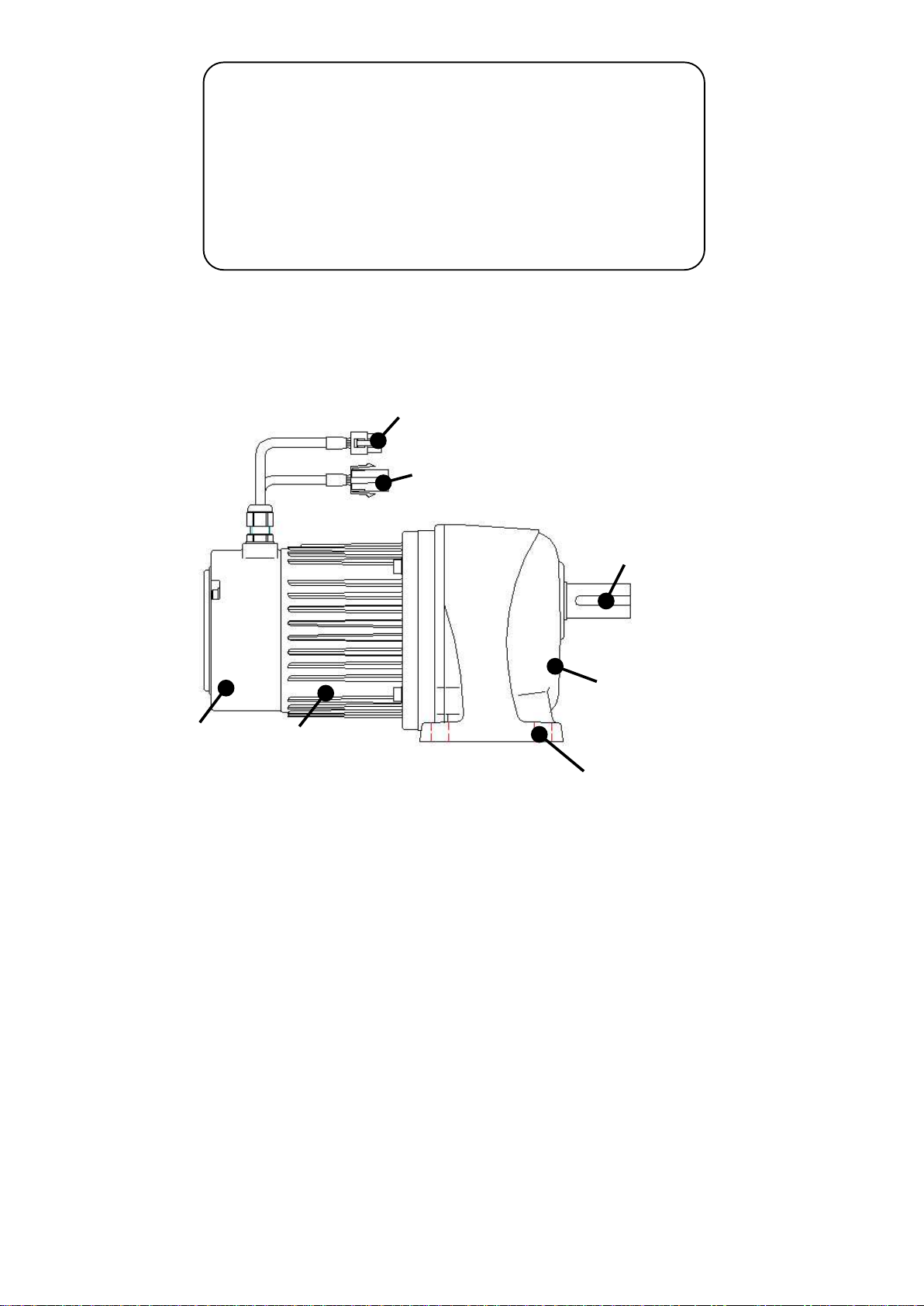
PartsNameandFunctions
1
-
2
.
InitialChecks
(1)
(2) Noaccidentaldamagetotheproductduringtransportationexist.
(3) Screwsornutsarenotloose.
(4) Components
a) Gearmotor
b) InstructionManual
c) Accessory
Theorderedproductsandthecontentsindicatedinthenameplatearecorrect.
(Type,Reductionratio,Motorcapacity,Voltage,Frequency,etc.)
Whenunpackingacarton,pleasecheckupthefollowings.Ifyouhaveanyproblems
orquestions,pleasecontactthedealerfromwhichtheproductwassuppliedora
salesoffice.
Output
Shaft
MotorPowerCable
(IncludeBrakeLeads)
MotorSignalCable
Gearhead
Foot
Motor
Brake
3

2.Installation
2
-
1
.
Connection
Connecteachdevicesasshownbelow.
Besuretoinsertthecorrectconnectorsurely.
※
※ Thecablethatcomeswiththegearmotorextends200mm.
※ Donotconnectordisconnectwiringwhilethepowerison.
Itmaycausemalfunctionoftheproduct.
※
ExtensionPowerCableandExtensionSignalCablearerequiredtoconnect
GearmotorandDriver.
WhenQtype(withbraketype)isused,thepowersupplyof24VDC(10mAor
more)isnecessaryasidefromoptionalbrakepowersupplydevice.
ToON・OFFthebrake,ourregularoptionisnotalwaysnecessary.Itis
possibletoaddDC24VbetweenBandBofthepowercable.However,the
varistor(82Vand1Jormore)orthediode(100Vand1Aormore)is
necessarybetweenBandBtoprotectthebrakecoilandcontactpointof
therelay.
BrakePowerSupplyDevice
BrakeControl
Wire
APQGearmotor
RegenerativeResistor
Extension
PowerCable
Extension
SignalCable
APQDriver
PowerSupply
Cable
+24V
0V
24VDC
(customer
preparation)
QType(withBrake)
4
2
-
2
.
InstallationofGearmotor
(
1
)
Properlocationforinstallation
(
4
)
TighteningTorque
AmbientTemperature:0℃to40℃
AmbientHumidity:85%max.
Altitude:Sealevelto1,000mmax.
Environment:Wellventilatedplacefreefrom
corrosivegas,explosivegasvapor
and/ordust.
InstallationLocation:Indoors
(2) DirectionofInstallation
(3) MethodforInstallation
① Attachingthemountingfootandflange
(Roughnessofthesurfaceshouldbelessthan0.3mm.)
② Attachingtheshaft
● Gearmotor'sweightshouldbesupportedbythedrivenshaft.
●
2
-
3
.
Connectingwithotherequipment
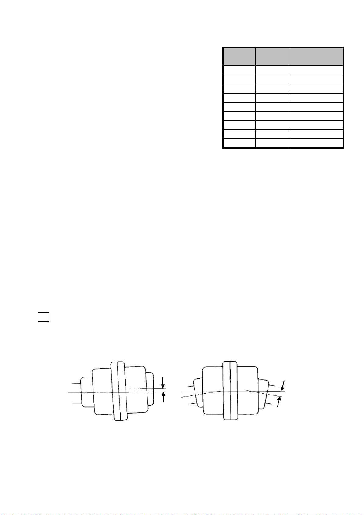
1 DirectConnection
●Anexampleofgearcoupling
● Thedisplacementsδandθshouldbeminimizedasmuchaspossible.
●
Loosefitisrecommendedforthecouplerssuchascouplings,sprockets,pulleys,
gears,etc.,whenattachingtothereducer,usingthedesignatedkeymaterials.
Thisproductcanbeinstalledinanydirection
duetoagreaselubricationsystem.
Thedisplacementsδandθdifferaccordingtothetypeofcoupling.
Therefore,theyshouldbewithintheallowablevaluedefinedbytherespective
manufacturer.(Reference:Incaseofchaincoupling,δshouldbewithin2%of
therollerchainpitchandδshouldbewithin1°.)
M5
M16 294{30}
(Forcesotherthanturningreactiveforceshouldneverbeimposedto
thetorquearm.)
108{11}
BoltSize
Incasestart/stopandforward/reverseactionsarefrequent,tightenup
thetorquearmwithboltstokeepthelockingholenotloose.
M12
5.5
6.5
8.5 M8 13{1.3}9 13{1.3}
11
13
15 M14
M10
(N・m){(kgf・m
)}
Connectthereducertotheotherequipmentprecisely,sothatthe
centeroftheshaftofbothmachineswillbefullyaligned.
18
22 M20
69{7.0}
fixinghole
(mm)
25{2.6}
44{4.5}
M6
M8
TighteningTorque
2.9{0.3}
4.9{0.5}
Fixtheproductwiththefourboltsonaflatandmachinedsurfacefree
fromvibration.
δθ
5

2 AttachingChains,V-Belts,Gears,etc.
①
②
③
・
・
・
Thechainistooloose.
・
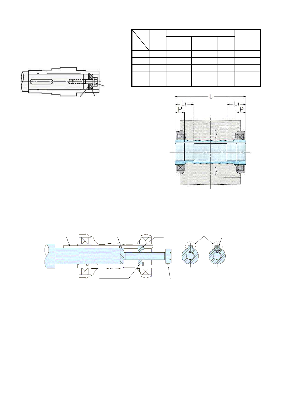
3 AttachingandDetachingaDrivenShaftto/fromAF3STypeHollowShaft
●AttachingaDrivenShafttotheReducerHollowShaft
①
②
③
④
⑤
Tensionsforbeltandchain
arecorrect.
ThetensionoftheChains/V-Beltsandthecouplingofthegearmustbeperpendiculartothe
centeroftheshaft.
Inanyconnection,connecttheunitsprecisely,sothatthecenteroftheshaftofthereducer
andthatoftheotherequipmentareparallel.
Thepositionsofpulleyand
sprocketarealsocorrect.
Incaseimpactdoesnotapplyintheuniformload,loosefitisrecommendedforthefittolerance
ofdrivenshaft.Incaseshockloadorheavyradialloadisappliedtotheshaft,thefitshouldbe
tighter.Theboreofthehollowshaftismachinedtoconformto"JISH8"tolerance.
Thelengthofthedrivenshaftandthefixingkeyarerecommendedtobewithinthearea
where"H8"toleranceforthefixedsideboreisrequired.
Itisrecommendedtominimizethefluctuationofthedrivenshaftbelow0.05attheshaft
edge.Thegreaterfluctuationmaygiveharmfuleffecttothereducer.
Thesprocketispositioned
inthereversedirectionso
thattheloadpointmoves
totheshaftedge.
Whenattaching,besuretosmearextremepressureagent(molybdenumdisulfide,etc.)onthe
surfaceofdrivenshaftandtheboreofthehollowshafttoavoidseizing,andinsertthereducer
tothedrivenshaft.
Ifthefittingistootight,forsmoothinsertion,knockonthehollowdriveshaftendgentlywith
plastichammer.Inthiscasebesurenottohitthecasing.Smootherinsertioncanbeobtainedif
youpreparejigsshowninthefigurebelow.
TensionoftheV-Belt:Excessivetensioningmayresultindamagetothebearingsoftheshaft.
TensionoftheChain:Excessivetensioningmayresultindamagetothebearingsoftheshaft.If
thechainisinstalledloosely,shockloadwilloccurwhenthedriveshaftstartsrotation,andthis
canresultindamagetothereducerandtheotherequipment.Therefore,adjustthetensionof
thechainproperly.
DrivenShaft
Key
Areawherethetolerance
oftheboreshouldbe
within"H8" Hollow
Shaft
Areawherethetolerance
oftheboreshouldbe
within"H8"(fixedside).
Spacer
Nut (Outputshaftcanbe
insertedbytightening
thenut.)
Bolt
Bearing
OilSeal
Figue-1
※Spacer,nut,bolt,keyand
otherpartsforbearingshould
bepreparedbycustomer.
Connecting
machine
sprocket
Connecting
machine
ProperWayofUse
BadExample
6

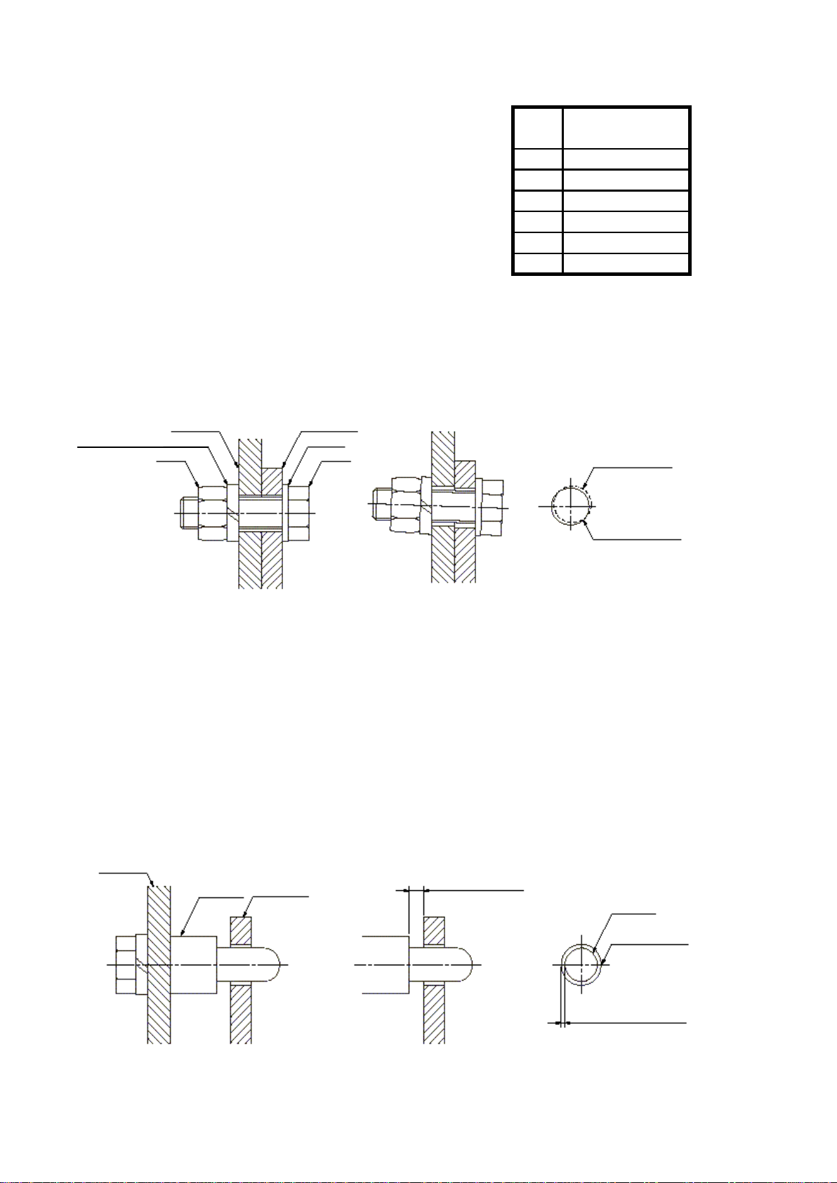
●ConnectingReducerwithDrivenShaft
① Drivenshaftwithashoulder
Note)Excessivetighteningoftheboltmaycausethedeformationofthesnapring,whichcarefullynote.
② Drivenshaftwithoutashoulder
Note) Besuretohavespaceintheouterdiameterofspacerandintheboreofhollowshaft.Excessive
tightnessofthefittingorinaccuracyofthespacer'sdiametermaybeacauseofscrubbingwhichmay
leadtoagreaterfluctuationbetweenthedrivenshaftandthehollowshaft.Positioningspacerisused
whendecidingthepositionofthereducer.Incasethelengthofthedrivenshaftisalreadyclarified,
positioningspacerisnotnecessary.Byhavingapositioningspacer,smootherdetachmentfromthe
hollowshaftcanbeobtained.(Formoredetailsaboutthedetachmentfromthehollowshaft,referto
Figure-5.)
Spacer
SnapRing
Fixthedrivenshaft
betweenthepillows
Bolt
Figure-2 Fixingbyspacerandsnapring
connecting
machine
Fixingthedrivenshaft
betweenthepillows.
Bolt
Endplate
Figure-3FixingbyEndplate
connecting
machine
※Spacer,boltandsnapring
shouldbepreparedbycustomer.
※Endplateandboltparts
shouldbepreparedbycustomer.
Fixingthedrivenshaft
betweenthepillows
Figure-4Fixingbyspacerandsnapring
Positioning
spacer
Bolt
Spacer
Snap
Ring
connecting
machine ※Spacer,positioningspacer,
boltandsnapringshould
bepreparedbycustomer.
7
●Recommendedsizeforthedriven
shaftfixingpart
〈
Recommendedsizeforthedrivenshaftfixingpart
〉
●Aboutthelengthofdrivenshaft
●Aboutthelengthofkeyforthedrivenshaft
●Detachingfromthehollowshaft
Figure-5
Thelengthofthekeyshouldbemorethan1.5timesof
thediameterofhollowshaft.Also,thekeyinserting
positionshouldbetheplacewheremorethan1/2of
thetotalkeylengthcanbereachedtoL1.(Referto
thefigureontheright)
Thedrivenshaftmustbereachedtothebothsideof
theL1part.(Asshownontherightfigure)However,be
suretohaveallowanceforthespacer'sdimension
necessaryatthe"detachmentfromthehollowshaft".
φ45
M6
M6
M8
M10
M12
φ30
φ25
φ20
φ35
Makesuretoavoidexcessiveforcebetweenthecasingandthehollowshaft.Smoother
detachmentcanbeobtainedbyusingajigasshowninthefigurebelow.
4
5
Width
φ7
35
45
φ34.5
φ44.5 φ11
φ11 5
φ29.5
Bolt
Size Inner
Diameter
φ19.5
φ24.5
Outer
Diameter
φ9
Fortheattachmentofthehollowshaft
ingeneraluse,werecommendyouto
refertothedimensionsshownonthe
rightasaguidelineforthestrength
whendesigning.
Nominal
Designation
forC-Type
SnapRing
20
25φ7 30
SpacerDimension
3
5
Bolt
Spacer
C-typesnapring
Key1
Disk
Snapring Key2
(Theconvexitypartisfor
thefixingpartofthe
Crosssectionofthespacer
Bolt
Spacer(withtap) (Bytighteningthebolt,
outputshaftcomesout.)
※Spacer,disk,boltandsnapring
shouldbepreparedbycustomer.
8

●AttachingReducer
Meritsanddemeritsofflangemountedandtorquearmmounted.
●AF3STypeHollowShaft・FlangeMounted
●DetailedDrawingfortheTappedHoleforFaceMount(StandardSpecification)
13 25 φ8.6 38
15 25 φ8.6 40
16 25 φ8.6 41
16 30 φ10.6 46
18 30 φ10.6 48
18 40 φ14 58
23 50 φ17.5 73
※
Valuesintheparenthesisinthe"FrameNumber"arethatforAF3F.
Thenecessaryholdingpartoftheboltarerecommendedtobetwiceasmuchasthe
nominaldesignation(boltdiameter)ofthescrew.
(Example:IncaseofM10,over20mmisrecommended.)
●Alignmentwiththe
connectingmachineisneeded.
Demerits
Flange
Mounted
45(40) φ16.5
1/80〜1/240 M16×P2
M20×P2.50.75kW φ20.5
0.4kW
35(32) 1/80〜1/240 φ12.5
0.4kW
1/80〜1/240 φ12.50.2kW
0.75kW
30(28)
WhentheAF3STypeunitisdirectlycoupledwiththe
flangefaceoftheothermachine,thealignmentshould
bedonepreciselytoavoidburnoutofmotor,damage
tothebearings,etc.causedbymisalignment.Inthe
AF3Series,thereisaborefortheattachmentas
showninthediagramontheright.Thedimension
toleranceoftheborefortheattachmentφAis"h7".
Thefixingboltsaretobeusedasshowninthe
diagramontheright.Fixby4bolts.
M10×P1.5
M10×P1.5
M12×P1.75
ReductionRatio Capacity A
1/10〜1/60 φ10.5
TorqueArm
Mounted
0.1kW
0.2kW
15(18)
25(22) 1/10〜1/160
1/10〜1/60
●Onlyonefixingpointisneededfor
fixingwithothermachine
φ10.5
φ10.5
●Torquearmisneeded.
F
●Spaceforattachingtorque
armisneeded.
M12×P1.75
M10×P1.5
B
●Easyalignmentwiththe
connectingmachine
1/5〜1/60
Frame
No. C D E
●Spacesaving
●Directattachmenttothemachine
ispossible.
Merits
4−B
CEFD
4−A
AF3SType
(HollowShaft)
Drivenshaftofthe
othermachine
Flangefaceofthe
othermachine
Boreforattachment
Fixingbolt(4pcs.)
φA
9
●FixingaReducerandaTorqueArm
BoltSizeandRespective
①
TighteningTorque
②
●HowtofixtheTorqueArmFixingPart
① IncaseofForward/ReverseOperation
Badexample
Figure-6Attachingthefixingpart
Note)
② IncaseofOne-DirectionOperation
Figure-7Exampleofusingpinwithshoulder
Excessforceariseninthedrivenshaftandthehollowshaftmay
causefailureofthemachine.
M14
13{1.3}
M12 25{2.6}
44{4.5}
69{7.0}
TighteningTorque
N・m{kf・m}
108{11}
294{30}
Bolt
Size
M20
M8
M10
Torquearmsaresubjectedtorotationreactiontorque,
therefore,theymustbestrongbyusingmaterialsof
enoughthicknessandboltstoenduretheshockload
onstarting/braking.Choosingouroptionaltorquearms
isthemostappropriatesolution.
Wheninstallingareducerwithatorquearm,besureto
tightentheboltusinghelicalspringlockwashersand
plainwashers.Forpropertighteningtorque,referto
thetableshownontheright.
Firmlyfixthefixingpartofthetorquearm.Makesurethatthereisnoradialload
(suspendingload)imposedbetweenthedrivenshaftandthehollowshaftofthereducer,
causedbypooralignmentbetweentheholeoffixingpartandtheconnectingmachine.
(RefertotheFigure-6)
Whenabacklashintheattachingpartarosebyforward/reverseoperationsorbyhighfrequencyof
starting/stopping,theintenseimpactgiventothetorquearmineachstartingmaycausethefailuressuch
aslooseningofthetighteningbolt.
Ifthefrequentstaringtorquelikeintheforward/reverseoperation,isnotobserved,
operationwiththereleasedfixingpartoftorquearmispossible.However,itisnecessary
tofixthedrivenshaftandthehollowshaft.(RefertotheFigure2,3and4)Inthiscase,
besuretosecureenoughspacebothforradialdirectionandforthrustdirectioninthe
alignmentbetweentheconnectingmachineandthefixingpart.
M16
holeofthetorquearm
pinwithshoulder
Securespacetoavoidtheradialload.
Securespaceforthehole
toavoidshouldering.
torquearm
pinwith
shoulder
connectingmachine
nut
connectingmachine
helicalspringlockwasher torquearm
plainwasher
bolt holeoftheconnecting
machineside
holeofthetorque
armside
10

3.Specifications
①MotorSpecifications
●
Capacity
(
kW
)
Item
MotorType
RatedCurrent
(
A
)
AmbientTemperature(℃)
Protection
②BrakeSpecifications
Capacity
(
kW
)
Item
Voltage
(
±
10
%)(
V
)
Current
(
at
20
℃
)(
A
)
Power
(
at
20
℃
)(
W
)
4.MaintenanceandLifetime
4
-
1
.
MaintenanceandLifetime
●
●
4
-
2
.
MethodforBrakeGapAdjustment
1
2
3
30
(mm) 200
2.0
MaximumExtension
Distance
0.36
0.2kW
0.1kW 0.2kW 0.4kW
0.4kW
BlushlessDCMotor
0to40℃
0.6
0.9
0.1kW
0.75kW
3.8
24
0.58
Totallyenclosednon-ventilated(IP65)
0.57 0.95 1.76 3.43
13.9
0.58
13.9
1.05
20.6
0.75kW
8.6
(N・m)
■Attachingdirectionofthe
castellatednut.
Thelifeofoilsealmayvaryaccordingtotheconditionofuse.Thereforereplacement
maybeneededevenwithin10,000hoursuse.
TheRatedCurrentdescribedinthefollowingtableisareferencevaluewithoutthe
gearhead.(motorunitonly)
"Power-off,Brake-on"Type
(SpringClose)
(m)
Allmodelsusegreaselubricant,withoutneedingreplacementorreplenishment.The
gearmotorhasbeendesignedforanapproximateuselifeof10,000hours.
LengthofMotor
LeadWire
BrakeType
HoldingTorque
(atmotorshaft)
Danger
Afterinspectionandadjustmentofthegap,donot
operatethemotorwiththebrakecoveropen.Failureto
observethiswarningmaycausewind-inandphysical
injury.
Whenadjustingthegap,besuretodisconnectthemotor
fromthepowersource.Failuretoobservethiswarning
maycausephysicalinjury.Intheeventofthecastellated
nutremoved,besuretoattachitintherightdirection.
Attachinginthewrongdirectionmaycausedamages.For
therightattachingdirection,refertotheattaching
directionofthecastellatednutshownright.
Afterinspectionandadjustmentofthegap,besureto
confirmifthebrakefunctionsproperlybyturningthe
switchonandoff.Failuretoobservethiswarningmay
causeaccidentbyfallingorrunoutofcontrol.
11
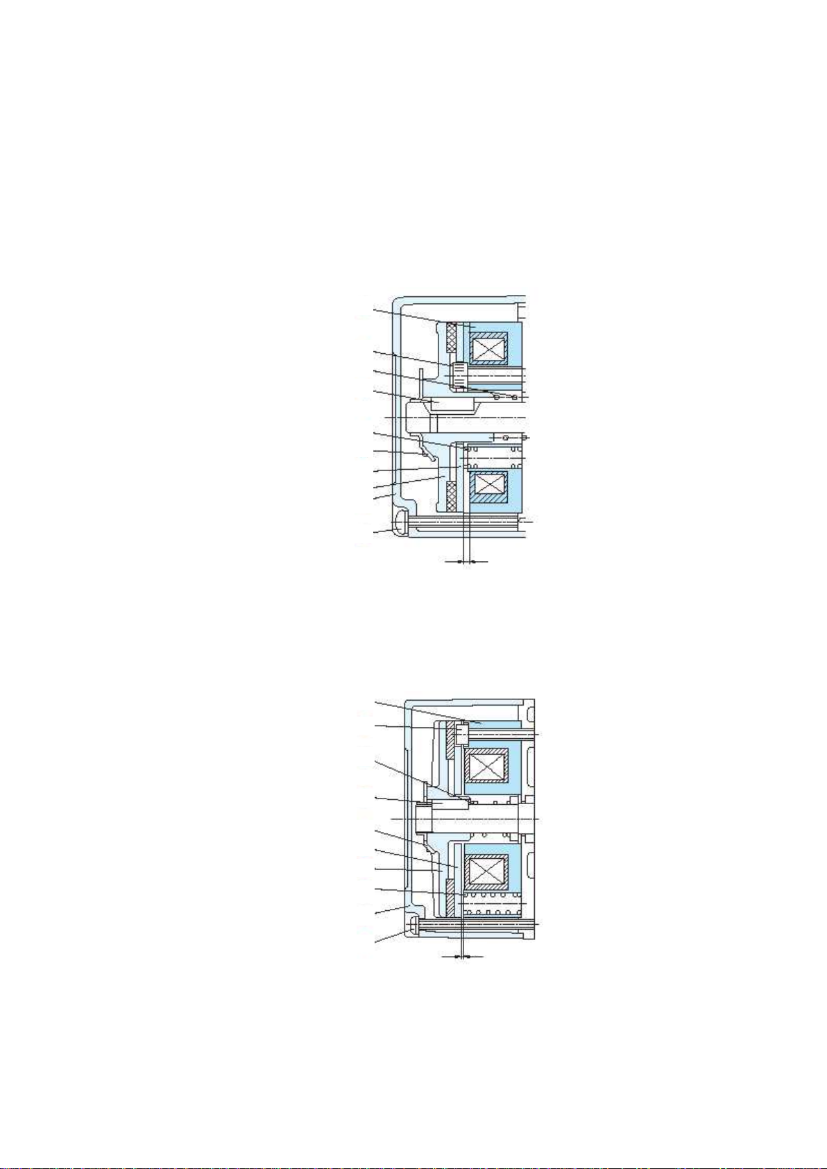
■QType(withBrake)
■Structureofbrake
0.1kW,0.2kWand0.4kW
①Field
②Armature
③OuterDisk
④Spring1
⑤Spring2
⑥CastellatedNut
⑦Key
⑧HexSocketHeadCapbolt
⑨BrakeCover
⑩Brakecoversettingbolt
※
ProperGap:0.4mm(±0.1mm)
GapforSuctionLimit:Lessthan0.7mm
0.75kW
①Field
②Armature
③OuterDisk
④Spring1
⑤Spring2
⑥CastellatedNut
⑦Key
⑧HexSocketHeadCapbolt
⑨BrakeCover
⑩Brakecoversettingbolt
※
ProperGap:0.2mm(±0.1mm)
GapforSuctionLimit:Lessthan0.5mm
Asaresultofusingbrakeforanextendedperiodoftime,naturallybrake
gapgrewandfinallybrakereleasingbecomeimpossible.Toavoidthis
trouble,besuretoadjustbrakegapperiodically.
Asaresultofusingbrakeforanextendedperiodoftime,naturallybrake
gapgrewandfinallybrakereleasingbecomeimpossible.Toavoidthis
trouble,besuretoadjustbrakegapperiodically.
Afteroperationforanextendedperiodoftime,thefrictiondiskofbrakebecomes
abradedandthegapincreases.Whenthegapclearancebecomesgreaterthanthelimitof
gaptoinhale,armatureinhalingbecomesdifficultbymagnet,makingitimpossibleto
releasethebrake.Whenusingthemotorcontinuouslywiththiscondition,theoperation
withbrake-oncausesoverloadandfinallyALARMLEDonthedriverlightsup,thenthe
motorwillstop.Inordertooperatethismachinesafely,itisrecommendedtocheckor
adjustthebrakegapperiodically(Every1yearorevery2to3millioncycles).
①
⑧
⑤
⑦
④
⑥
②
⑨
⑩
③
gap
③
①
⑧
⑤
⑦
⑥
②
④
⑨
⑩gap
12

5.Troubleshooting
Improperinstallationorslacked
bolts.
Foreignsubstancesoroilare
adheredtothefrictiondisk.
Disconnectionorshortcircuitof
brakecoil.
Whenthedefectiveoperationisfound,pleasecheckthecauseandtakemeasures
accordingtothefollowingpoints.
Disconnectionofmotorpower
cable.
Disconnectionorpoorcontactof
motorsignalcable.
Motorpowercableistoolong.
Continuednoise-defective
bearing,wornoutgear.
Damagedswitch.
Lifeofthefrictiondisk.
Brokengear,shaftorbearing.
Wornoutgear.
Repairorreplacetheswitch.
Repairatauthorizedfactory.
Removeforeignsubstances.
Excessivemomentofloadinertia.
Largerbrakegap.
Poorcontactofswitch.
Repairatauthorizedfactory.
Reducetheloadinertia.
Adjustthebrakegap.
Repairatauthorizedfactory.
Tightenthebolts.
Repairatauthorizedfactory.
Wornoutgearorbearing.
Reducethefrequency.
Repairatauthorizedfactory.
Repairatauthorizedfactory.
Repairatauthorizedfactory.
Reducetheload.
Reducetheload.
Checkthelengthanddiameter
ofpowercable.
Overloadoperation.
Overloadoperation.
TroubleshootingCause
Repairatauthorizedfactory.
Checktheconnection.
Checktheconnection.
Intermittentnoise-damagedgear
orforeignsubstancesinsidethe
motor.
Replaceorrepairtheswitch.
Abnormalnoise
Highfrequencyofstartandstop.
Damagetobearings.
Themotordoesnot
runeveninthe
unloadedcondition.
Themotordoesnot
runintheloaded
condition.
Abnormalrisein
temperature
Trouble
Excessivevibration
Brakedoesnotwork
Brakefunctionisnot
enough.
Motordoesnotrun.
(Rotatingspeeddoes
notincrease.)
Overheatedmotor.
Abnormalnoisein
braking.
13

6.Warranty
1.WarrantyTerm
2.ScopeofWarranty
1) Thescopeofourwarrantyislimitedtoourmanufacture.
2)
3.ExceptionforWarranty
1)
2)
3)
4)
5) secondaryfailurecausedbythedamageofcustomersequipment.
6)
7)
8)
9)
Incasethatanyfailuresontheproductbywhichproperfunctionsofthe
productcannotbeobtainedariseduringtheabovewarrantyterm,although
theproductisproperlyoperatedundertheconditionthattheproductis
properlyinstalledin,connectedtothemachine,treated(including
inspectionandmaintenance)inaccordancewiththisInstructionManual,we
willprovideappropriaterepairontheproductfreeofcharge,exceptas
stipulatedintheExceptionforWarrantyasdescribedbelow.
anyothertroubles,problemsordamagesontheproductwhicharenot
attributabletoourproductliability.
Wearenotresponsibleforthecompensationagainstthelossofshutdown
and/orforthedamagetotheequipmentswhicharenotproducedbyus,
causedbytheinterruptionofoperationofourproduct.
anyrepairstothelossesordamagescausedbythedisassemble,
modification,changeofpartsorthesubstitutedproductdeliveredwhich
arerenderedbycustomer.
anylossescausedbytheparts,drivingunits(examples:electricmotor,
servomotor,hydraulicmotor,etc.)whicharesuppliedbycustomer.
improperstorageandmaintenanceoftheproduct,orimproperhandlingof
theproduct.
disaster(earthquake,thunder,fire,flood,etc.)orhumanerrorsuchas
wrongoperationoftheproduct.
customer'simproperoperationoftheproductnotinconformitywiththe
rateddataspecifiedinourcataloguesorthespecificationsmutuallyagreed.
anyfailuresinthetransmissionparttocustomer'sequipment(alignmentof
theshaftwhencouplingwithothermachine,etc.)
Thiswarrantyshallnotbeappliedtotheproblems,troublesordamagesonthe
productwhicharecausedby:
Thewarrantytermfortheproductshallbe18monthsafterthedateof
deliveryor12monthfromtheproductstartingoperation,whetherbe
shorter.
14

NISSEICORPORATION
Sales,OverseasDivision
1-1Inoue,Izumi-cho,Anjo-shi,Aichi,444-1297JAPAN
TEL:+81-566-92-5312FAX:+81-566-92-7002
ver
1.0
2010/4
Ifyouhaveanyquestionsorconcernsabout
ourproduct,pleasecontactthedealeror
distributorfromwhompurchased,orcontact
thenearestsalesofficeorplantof
NisseiCorporation.
Acceptance
Certificate
This manual suits for next models
1
Table of contents
Other Nissei Engine manuals


Popular Engine manuals by other brands

Briggs & Stratton
Briggs & Stratton 120000 Operating & maintenance instructions

Volvo
Volvo D11F Operator's manual and maintenance instructions

Chris-Craft
Chris-Craft 350-Q Operator's manual

Vauth-Sagel
Vauth-Sagel HSA power move OPERATING AND INSTALLATION Manual

GAPOSA
GAPOSA XQ40 instructions

Suzuki
Suzuki DF 25 owner's manual

Briggs & Stratton
Briggs & Stratton 351700 Series Operating & maintenance instructions

Mercedes-Benz
Mercedes-Benz OM602 Service manual

Leadshine
Leadshine iSV2-CAN Series user manual

Kohler
Kohler KDI 1903M owner's manual

Festo
Festo MTR-DCI series Brief overview

Westerbeke
Westerbeke 12B TWO Operator's manual


