Nissei GTR ECO Series Operating and maintenance manual
<Please read this manual before using the product.>
Contents of this manual is based on using with our specialized inverter.
When operating with other inverters, make sure to check
「14. Notes on operating with inverters other than the specialized inverter」.
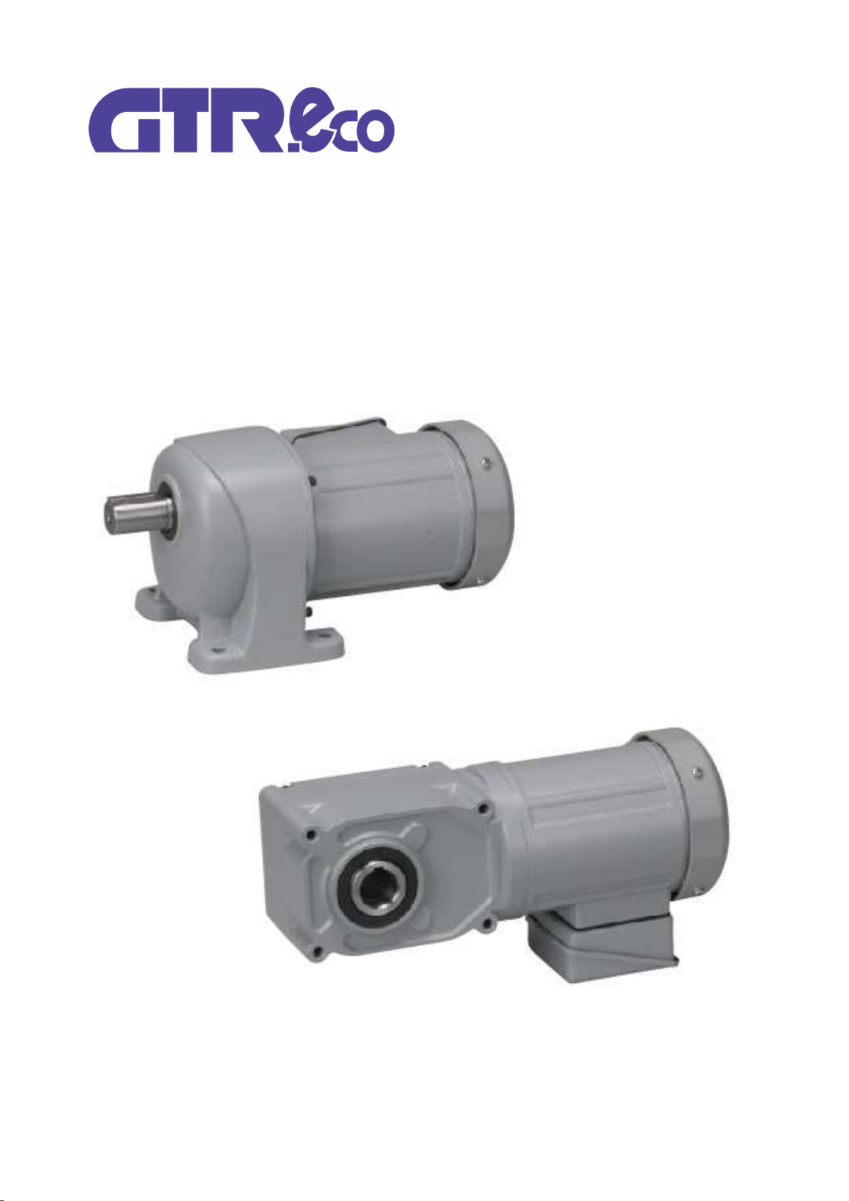
GTR eco SERIES(0.1kW〜2.2kW)
Detailed Instruction Manual
IPM gearmotor
Nissei Corporation
・
Be sure to carefully read the contents described in this instruction manual and to understand how to use
product correctly before using it.
・
The extent of hazard/damage expected to occur in the case of improper handling are classified and indicated
in ranks of “DANGER”, ”WARNING”, and ”CAUTION.” The definitions and indications are as follows.
■Description of symbols
Even items described in “CAUTION” may lead to a serious results depending on the situation.
Be sure to observe every instruction which deals with important contents.
Danger
■The types of contents to be observed are explained with classification by graphical symbols below.
Cases where it is expected that a degree of danger is extremely high such that improper
handling possibly causes a dangerous situation to occur, which may lead to death or
serious injury.
Cases where improper handling possibly causes a dangerous situation to occur, which may
lead to death or serious injury.
Cases where improper handling possibly causes a dangerous situation to occur, from which
a minor or medium degree of injury may be incurred.
Indicates "Fire hazard."
Indicates "What You Must Not Do."
Indicates "Do Not Disassemble."
Indicates "What You Must Do."
Indicates "Ground Connection."
Warning
Do not perform wiring as voltage is generated at the motor ternimals, while the motor is running,
even when the power has been turned off. Otherwise, an electric shock may occur.
Never perform operations with wet hands. Failure to follow this precaution may result in electric
shock.
If the product is used in an elevator, install a safety device on the application to prevent it from
falling. Failure to implement safety measures may result in personal injury, death, and/or damage to
the application due to the falling of the elevator.
DANGER
IPM motors cannot be driven with a commercial power supply. If commercial power supply is applied
to the input terminals(U, V, W) of motor, the motor will be burned. Always connect them to the
output terminals(U, V, W) of the driver compatible with PM motor.
Use an explosion-proof motor that complies with operation under the explosive atmosphere. Failure
to follow this precaution may result in explosions, ignition of fire, fire, electric shocks, injuries, and/or
damage to the application.
If the product is used in an application such as a personnel transport device, make sure to install a
protective device for safety purposes. Failure to implement safety measures may result in personal
injury, death, and/or damage to the application.
Do not come close or touch the rotating parts (output shafts, etc.) while the product is in operation.
Failure to follow this precaution may result in injury due to entanglement.
WARNING
The operators in charge of transportation, installation, wiring, operation, handling, maintenance, and
inspection should have enough knowledge and technical skill related to the product. Failure to follow
this precaution may result in explosion, ignition of fire, fire, electric shock, injury, and/or damage to
the application.
When the operation has stopped due to the occurance of error or activated safeguards, do not re-
start the operation until the causes of error are determined and countermeasures are taken.
Failure to follow this precaution may result in damage to the application, injury, fire, electric shock,
and/or burns.
Caution
Indicates "What You Must Pay Attention To."
Indicates "Burn Hazard."
Indicates "Electric Shock Hazard."
Introduction
Thank you very much for purchasing our product.
Safety Precautions
2
WARNING
Do not expose the product to strong impacts/shocks. Failure to observe this precaution may result in
failure of the product and/or injury.
Be careful not to cause damage to the cable nor pull it strongly. Failure to follow this precaution may
result in injury, fire, and/or electric shock.
CAUTION
Do not repair, disassemble or remodel the product. Failure to observe this precaution may result in
injury, fire, electric shock, and/or burns.
Operate the product under the conditions specified in this instruction manual. Failure to follow this
precaution may result in damage to the equipment or injury.
When performing trial operation, fix the product in place and disconnect it from the application.
Failure to observe this precaution may result in injury.
Be sure not to get water or oil/grease into the brake unit. Failure to follow this precaution may result
in falling or out-of-control accident due to the decreased brake torque.
The product must be transported correctly in accordance with its weight.
Do not overload/over stack the products. Failure to follow this precaution may result in injury and/or
equipment failure.
When handling the gearmotor, be careful with the sharp edges/points of the application. Failure to
follow this precaution may result in injury.
We shall assume no responsibility or liability for any troubles caused by use that violates the cautions above.
The contents of this manual are subject to change without notice.
We have made every possible effort to make the contents of this manual easy to understand. If there is anything
that is unclear or hard to understand, please feel free to contact us.
Important
When disposing of the product, dispose of it as a general industrial waste. Please follow local laws and
regulations if any apply and take care of the waste accordingly.
Notice
Products modified by a customer will not be covered by our warranty.
Do not insert fingers or objects in the open parts of the product. Failure to follow this precaution
may result in electric shock, injury, fire, and/or damage to the application.
Make sure that the gearmotor is correctly wired. Failure to follow this precaution may result in injury
due to damaged equipment.
Do not touch the rotating part of the gearmotor. Failure to follow this precaution may result in
injury.
Do not use the gearmotor under conditions other than specified on the nameplate or the product
specification. Failure to follow this precaution may result in electric shock, injury, fire, and/or
damage to the application.
Do not use damaged products.
Failure to follow this precaution may result in injury, fire, and/or damage to the application.
Do not remove the nameplate.
Do not put any object that may prevent air from being circulated around the product. Failure to
follow this precaution can cause abnormal overheating of the product. It may result in fire or burns.
Do not stand on or place any heavy object on the product. Failure to follow this precaution may
result in injury
Fix the gearmotor firmly in place. Failure to follow this precaution may result in damage to the
equipment or injury.
Do not touch the gearmotor when the power is on or immediately after turning off the power, as
their surfaces may be hot for a while. Failure to follow this precaution may cause burns.
Immediately stop the operation if there is any abnormality. Failure to follow this precaution may
result in fire, and/or injury.
Do not put any combustible material near the product. Failure to follow this precaution may result in
fire.
3

14. Notes on operating with inverters
other than the specialized inverter
Contact Us P.41
P.40
1. Inspection upon Unpacking P.5
2. Transportation P.8
3. Installation P.8
P.9
5. Rotational Direction P.17
6. Wiring P.21
4. Connecting with Other Equipment
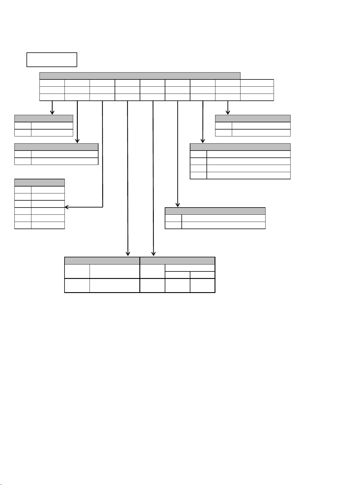
Table of Contents
Introduction P.2
Safety Precautions P.2
13. Guarantee P.38
9. Inspection and Adjustment P.32
10. Troubleshooting P.37
11. Disposal P.38
7. Operation・Specifications P.27
8. Standards P.30
12. Storage P.38
4

Check for the following items when unpacking the package.
(1)
Is the information on the nameplate consistent with your order?
(Gearmotor Model, Reduction Ratio, Motor Power, Voltage, etc.)
(2)
Were any parts damaged during transportation?
(3)
Are there any loose screws, bolts, or nuts?
(4)
Is there a nut included for connecting the terminal block?
(5)
In the case of a gearmotor with a brake, is there a rectifier included in the package?
The following is a typical nameplate.
・
Please refer to the next page for the product name.
・
The option code may not be listed.
・
In the case of an inquiry, please provide the product name/option code, reduction ratio and MFG. NO.
2
3
5
6
7
Option Code
Product Name
4
Manufacturing Number (MFG NO.)
Standards Number
CAUTION
Check whether the product is consistent with your order.
Injury, damage to the application, etc. may occur if the wrong product is installed.
Check the top and bottom of the package before opening it. Failure to follow this precaution
may result in injury.
1-1. Checking Package Contents
1-2. Details of Nameplate
No.
1
Contact the dealer from where you purchased the product or your nearest service office if you have
any questions or if there are any defects.
Standards Conformance
Discription
In the case of a terminal box with a built-in rectifier(option), check if the rectifier is built in to the
terminal box.
Insulation Class
IP Rating
Motor Characteristics
Motor Power/No. of Poles/
Reduction ratio
8
9
1.Inspection upon Unpacking
5
The gearhead model and motor model are described separately.
・
・
Only Frame No. 22 for ②Mounting F: Flange support of ①Series H2︓Right angle shaft.
・
Up to Capacity: 0.75 kW for ②Mounting F: Solid shaft of ①Series F︓Right angle shaft.
・
The ③Frame Number depends on the lineup of each series.
・
⑤Reduction ratios are 12X for 1200 and 15X for 1500 as they are displayed with up to three digits.
Up to and including Frame No. 32 for ②Mounting K: Small flange support of ①Series G3︓Parallel shaft.
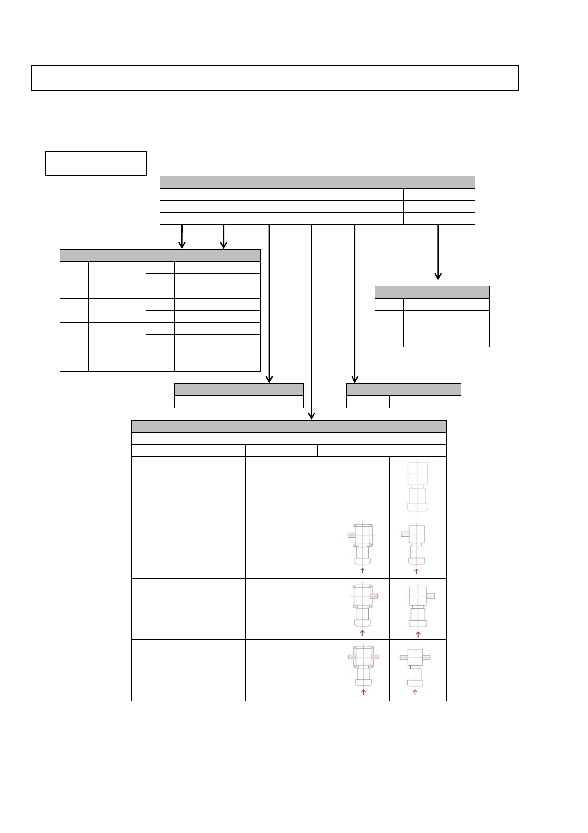
1-3. Gearmotor Model
■Gearhead Model
Descriptions of the symbols for gearmotor model are as follows. Check if the model is consistent with
your order.
ー
ー
④
Shaft
G3
L
N
①Series
②Mounting
Series
Mounting
Frame No.
28
R M
T B
Hollow Shaft
F
Solid Shaft
S
L
F
Output Shaft Diameter
Output shaft direction of right angle shaft type
(Right Angle
Shaft)
Flange Mount
G3 Parallel
Shaft
L
Foot Mount
①
②
③
H2 Right Angle
Shaft
L
Foot Mount
F
F3
(Concentric Right
Angle Shaft)
S
Solid Shaft
S
Hollow Shaft
③Frame No.
H
Material
□□
S43C
SUS420J2
Shaft Direction
H2
⑤Reduction Ratio
④Shaft
F/F3
N
Normal
Backlash 30 arcmin
(except for some
models)
L
Gearhead Model
⑥Backlash
F
Flange Mount
K
Small Flange Mount
⑥
⑤
Backlash
Reduction Ratio
N
10
F
5〜15X
1/5〜1/1500
The output shaft
protrudes from the
left when looking
from the input shaft
side(↑)
The output shaft
protrudes from the
right when looking
from the input shaft
side(↑)
The output shaft
protrudes from both
sides when looking
from the input shaft
side(↑)
ー ーN
6
・
⑮ Option code is added to specify the appropriate option. The main options are as follows.
For more details regarding options, please refer to the catalog or contact us.
■Motor Model
Wiring instructions for terminal boxes with built-in rectifier, terminal box mounting orientation,
change of lead wire outlet hole direction, encoder, fan installation, etc.
ー
ー
V
Water-resistant(IP65)
X
Designates a special option
⑦Motor Type
⑭Option
P
J2
⑬Brake
D
N
Without brake and encoder
02
0.2kW
V2
E
15
1.5kW
T
22
04
0.4kW
08
0.75kW
2.2kW
01
Motor Model
Option
0.75kW to 2.2kW
⑧Motor Spec.
M
⑨Motor Power
Symbol
N
⑩Supply Voltage
Symbol
V
Voltage(V)
200〜230
⑭
With manual release device, 200V brake
B2
X
Box
B2
200V brake
Standard
08
N
V
Power
Voltage
Standards
Type
Spec.
P
0.1kW
⑦
⑧
⑨
⑩
⑪
⑫
⑬
T
D
0.1kW to 0.4kW
Brake
Water-resistant 200V brake
Blank
Standard
⑮
X1
Option Code
⑫Terminal Box
Safety Standards
⑪Standards
UL
CE
○ ○
T type terminal box(Steel plate)
E type terminal box(Aluminum)
7
Pay attention to the following points as installation quality affects the lifespan of the gearmotor.
2.Transportation
DANGER
Do not enter underneath the product when it is lifted for transportation.
Otherwise, accidents caused by dropping may occur.
CAUTION
Check the weight of the gearmotor with the nameplate, packaging box, appearance diagram,
catalog, etc. Do not lift a gearmotor whose mass is more than the rated load of the
ceiling/application hook. Otherwise, bolt damage, injury due to dropping/falling and application
damage may occur.
If the package is made of wood, it is unstable to lift the package from the bottom when a lift is
used. It is recommended to use a belt to hold the package when lifting.
Do not move the gearmotor by holding only the terminal box. Otherwise, injury and application
damage may occur.
3.Installation
DANGER
Insulate the terminals when rotating the motor by turning the output shaft.
Otherwise an electric shock may occur.
Dropping and falling of the product during transportation is dangerous. Please pay sufficient
attention to prevent this. For a gearmotor with a hook, be sure to check that the hook is not
loose before using it. However, do not lift the application with the hook of the attached
gearmotor. Otherwise, hook damage, injury due to dropping/falling and application damage
may occur.
CAUTION
Do not place flammable items around the gearmotor. Otherwise, a fire may occur.
Do not place obstacles that disturb ventilation around the gearmotor. Cooling for the gearmotor
may be disturbed and burn/fire may occur due to abnormal overheating.
Do not step on/hang from the gearmotor and terminal box. Otherwise, an injury may occur.
Do not touch gearmotor keyways with a bare hand. Otherwise, an injury may occur.
Install an oil pan for a food machinery and other applications in which leakage cannot be
present and may occur in the event of a failure, service life, etc. Otherwise, products may be
defective due to oil leakage.
The guidance value of vibration from the mounting surface of the gearmotor or applied
externally is 0.5 G or less.
Pay attention to the transportation atmosphere because dew condensation occurs easily on sea
transportation. Dew condensation may occur inside of the box if the ambient temperature
rapidly changes in a high temperature/humidity atmosphere.
Pay attention to freezing under temperatures of 0°C or lower as freezing may cause a short
circuit between terminals. Otherwise, an electric shock may occur.
Wear debris of the brake, iron powder (metal pieces), etc. may be scattered after continuous
use. Mount a preventive device for food machinery and other applications which will result in
defective products due to contamination of foreign substances. Otherwise, the product, etc.
may be defective.
8

■Location
No restriction on installation orientation. (Since it uses a grease lubrication system)
①
Foot Mount, Flange Mount
Secure the gearmotor with four bolts on a vibration-free and flat machine-processed surface
(0.3 mm or less of flatness).
②
Shaft Mount (torque arm)
The drive shaft must be able to carry the weight of the reducer.
Note)
Force other than the rotational reaction force should not be applied to the torque arm.
(N・m)
{(kgf・m)}
M10
25
M5
2.9
{0.3}
M6
4.9
{0.5}
Bolt size
Tightening torque
Pay attention to the centering, belt tensioning, pulley alignment, etc. when the gearmotor is
connected to the load. In the case of a direct connection, make sure the connection is
precise. When using a belt, make sure to adjust the belt tension correctly. Be sure to
tighten the bolts for the pulley and couplings before operation. Otherwise, injury and
application damage may occur due to the scattering of broken pieces.
Mounting hole
(mm)
5.5
6.5
8.5
9
11
13
15
Ambient temperature
Ambient humidity
85% or less (no dew condensation)
Indoor
-10℃〜40℃
Water-resistant(IP65)
-10℃〜40℃
100% or less (no dew condensation)
Altitude
Atmosphere
Installation location
1,000m or lower
A place with no corrosive/explosive
gas/vapor, etc.
A place with good ventilation
without dust.
Indoors
1,000m or lower
A place with no corrosive/explosive
gas/vapor, etc.
Not to be used underwater or in
places where high water pressure is
applied.
Indoors/Outdoors
■Tightening Torque for Installation Bolts (Reference value)
■Procedure
■Orientation
{2.6}
M12
44
{4.5}
M8
13
{1.3}
M8
13
{1.3}
M20
294
{30.0}
4.Connecting with Other Equipment
CAUTION
M14
69
{7.0}
M16
108
{11.0}
18
22
Apply a cover, etc. so that rotation parts are not exposed. Otherwise, injury may occur.
Be sure to use the specified key to assemble the connection device (a coupling/sprocket/pulley/gear,
etc.) to the reducer shaft with a fit of about H7 class.
9
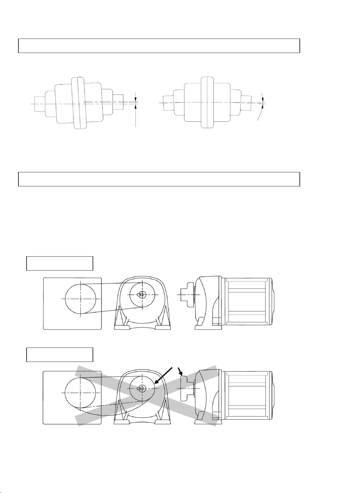
The shaft center of the application and the shaft center of the reducer must be aligned axially.
・
The displacement amount of δ and θ should be minimized.
・
(1)
The shaft center of the application and the shaft center of the reducer must be parallel to each other.
(2)
Chain, V-belt tension and gear engagement must be at a right angle to the output shaft.
(3)
V-belt tension
︓
If it is too tight, the bearing may become damaged.
Chain tension
︓
4-1. When directly connected
4-2. Attaching Chains, V-belts, Gears, etc.
The δ and θ differ according to the type of coupling. Therefore, they should be within the
allowable value defined by the manufacturer.
■Correct
■Incorrect
(Reference: In the case of chain coupling, δ should be within 2% of the roller chain pitch and θ
should be within 1°)
If it is too tight, the bearing may become damaged. High impact forces may
also occur if it is too loose, it would result in adverse effects on the reducer
and application. The tension of the chain should be correctly adjusted.
■Coupling Example
Application
Sprocket
Application ●
The chain is too loose.
●The tension of the V-belt and chain are properly set.
The pulley and sprocket are properly positioned.
●The sprocket is positioned in the
reverse direction causing the load
point to move to the shaft edge.
δ
θ
10

・
・
・
(Customers need to provide their own spacer, nuts, bolts, keys and shaft bearings.)
・
・
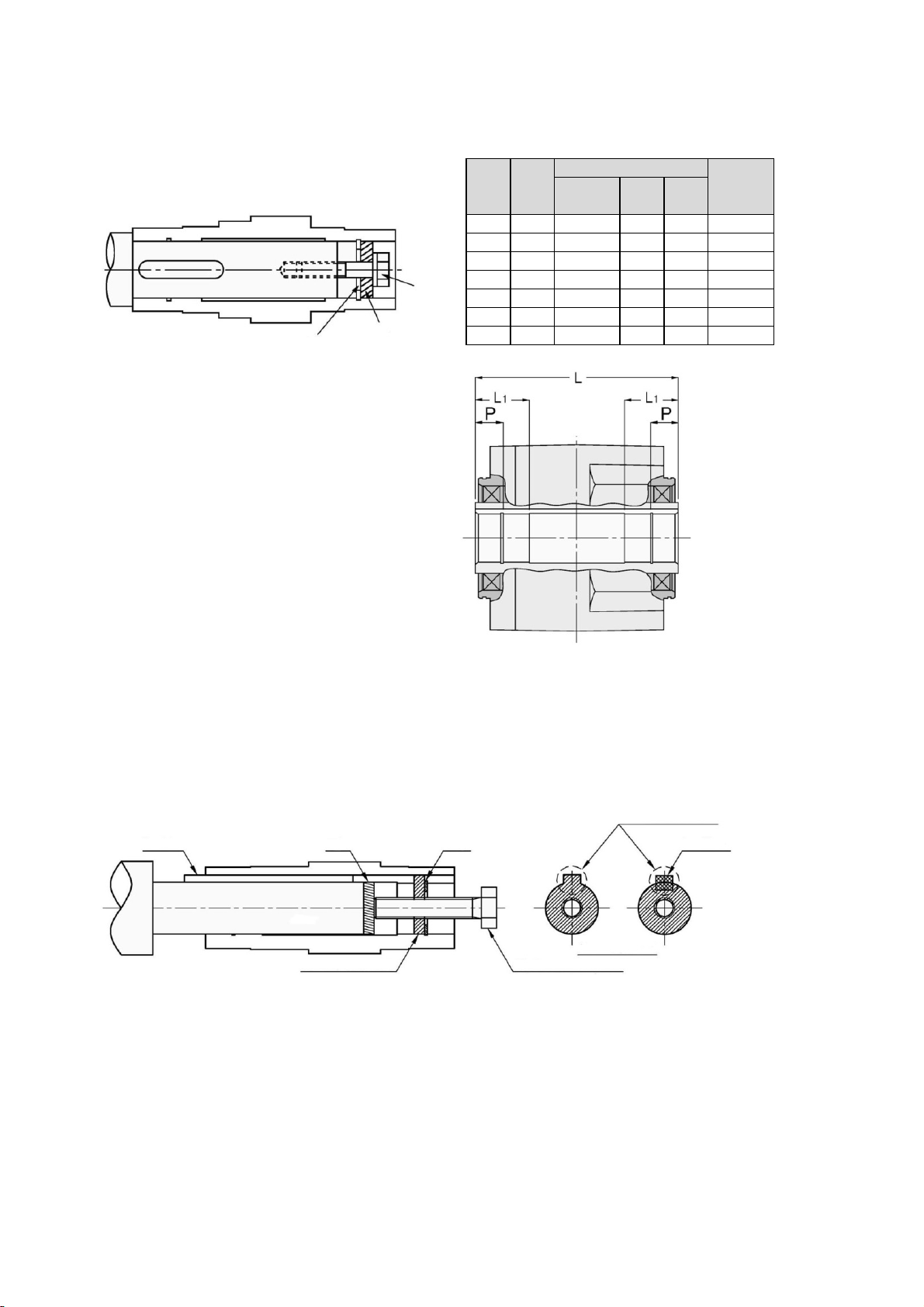
■Connecting the reducer to the drive shaft
①
When there are steps on the drive shaft
Figure. Attachment Using a Spacer and Retaining Ring
(Customers need to provide their own spacer, bolts, and retaining rings.)
Note)
Be careful when tightening the bolt, as tightening it too much can distort the shape of the
retaining ring.
When used with uniform loads, a drive shaft tolerance of h7 is recommended. Additionally, when
dealing with impact loads or large radial loads, make sure they fit each other tightly. The
tolerance of the interior surface of hollow shaft is designed to be H8.
If the shafts are a tight fit, use a plastic hammer on the end of the hollow shaft to insert it. When
doing so, be sure not to hit the casing. If you make a jig like the one in the diagram below, drive
shaft insertion will be easier.
4-3. Installing/Removing the FS/F3S Type Hollow Shaft
Coat the drive shaft surface and interior surface of the hollow shaft with a lubricant (molybdenum
disulfide) suitable to the atmosphere in which they will be used and connect the reducer to the
drive shaft.
■Installing the hollow shaft of reducer to the drive shaft
For the length of the turn-stop key for the drive shaft, tolerance range H8 for the internal
diameter on the fixed side is recommended.
It is recommended that axial runout for the shaft be 0.05 mm or less at the shaft end. If major
wobbling occurs during operation, it may have a negative effect on the reducer.
(Tighten the nut to insert
the output shaft.)
Key
Internal Diameter
Tolerance Range
H8
Hollow
Shaft
Fixed-End internal
Diameter Tolerance
Range H8
Spacer
Nut
Bolt
Bearing
Oil Seal
Drive Shaft
Retaining ring
Bolt
Spacer
Drive
shaft
Fi the drive shaft
between pillow
block bearings.
11

Figure. Attachment Using an Endplate
(Customers need to provide their own endplates and bolts.)
Note)
②
When the drive shaft has no steps
Figure. Attachment Using a Spacer and Retaining Ring
(Customers need to provide their own spacer, positioning spacers, bolts, and retaining rings.)
Note)
In addition, please apply a protective cover when possible so that there is no injury due to
objects getting caught in the output shaft.
Make sure there is a gap between the outer diameter of the spacer and the internal
diameter of the hollow shaft. If the fit is too tight and the outer diameter of the spacer
is inaccurate, axial runout of the drive shaft and hollow shaft can result.
The positioning spacer is used to position the reducer. It is not required if you know the
length of the drive shaft in advance. In addition, attaching the positioning spacer allows
for smooth removal from the hollow shaft. (Refer to "■Removal from the hollow shaft"
on next page)
Please understand that for the connection method above, mounting of resin cover for the F
Series is not possible due to the bolt interference.
Drive
Shaft
Endplate
Bolt
Drive
Shaft
Bolt
Spacer
Retaining Ring
Positioning Spacer
Fi the drive shaft
between pillow block
bearings.
Fi the drive shaft
between the pillows.
12
■Recommended Sizes for the Fixing Elements of the Drive Shaft
〈Recommended sizes for the fixing elements〉
Make sure there is enough room at the end of the hollow shaft to use the jig shown below.
If you make and use a jig like the one below, drive shaft removal will be easier.
(Customers need to provide their own spacers, round plates, bolts and retaining ring keys.)
φ
11
5
45
■Drive Shaft Key Length
■Drive Shaft Length
(See the figure to the right.) However, take
note of how much room is necessay for spacers
in the section titled “■Removal from the hollow
shaft.”
(mm)
M12
φ
49.5
φ
13
6
50
φ
45
M10
φ
44.5
C-shaped
retaining
ring for
holes
Spacer dimensions
When attaching the hollow shaft in general
use, refer to the dimensions shown below as
a guideline when designing.
φ
35
M10
φ
34.5
φ
11
5
35
φ
30
M8
φ
29.5
φ
9
5
30
φ
50
■Removal from the Hollow Shaft
φ
25
M6
φ
24.5
φ
7
4
25
φ
20
M6
φ
19.5
φ
7
3
20
Hollow
shaft
hole
diameter
Bolt
size
Outer
diameter
Internal
diameter
Width
φ
55
M12
φ
54.5
φ
13
6
55
Additionally, the key should be inserted in such
a position that at least half its length is in L1.
(See the figure to the right.)
The length of the key should be at least 1.5
times the diameter of the hollow shaft.
(The drive shaft will slide out if this
bolt is tightened. )
Bolt
Spacer
C-Shaped Retaining Ring
Key 2
Spacer cross
section diagram
Key 1 Round Plate Retaining Ring
Spacer (with tap) Bolt
The conve spacer
prevents rotation.
13
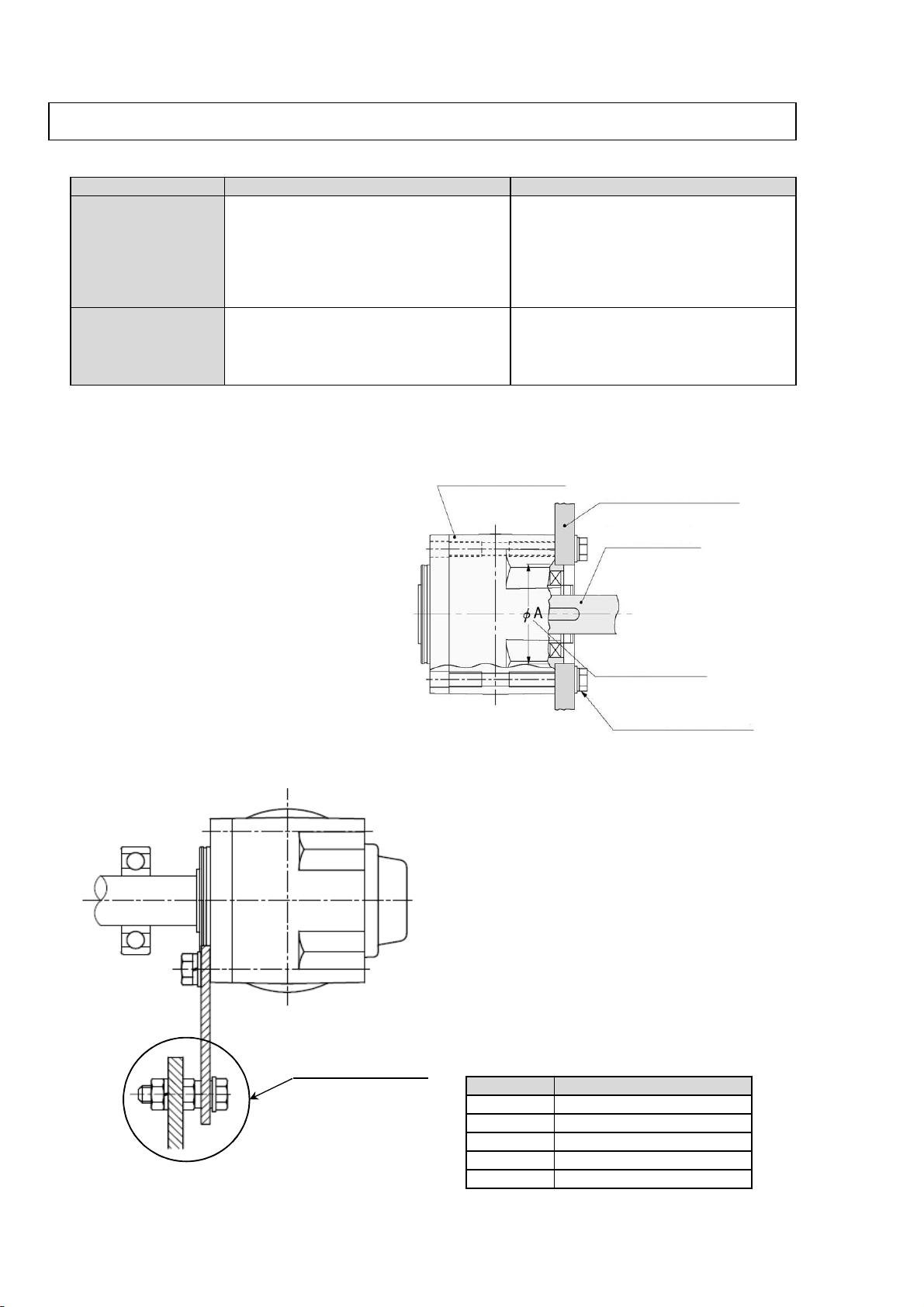
<Advantages and disadvantages of flange and torque arm installation>
●
●
●
Saves space.
●
●
●
●
●
●
Not suitable for position control
・
・
・
<Bolt Size and Tightening Torque>
(Reference value)
Fastening to the application only
requires one detent.
Makes centering with the
application easy.
Advantages
Disadvantages
Can be installed directly on the
application.
Centering with the application is
required.
Requires a torque arm.
Requires space for installing a
torque arm.
Torque Arm Installation
When the hollow bore is installed directly
to the flange of an application, it can
cause motor burn-out or bearing damage
if it is off-center, so be sure to center it
properly.
There is an installation guide, as shown in
the diagram to the right. The dimension
tolerance for ΦA on the installation guide
is h7 in the case of F3. The installation
bolts are installed as shown in the
diagram to the right. Four bolts should be
used.
To install the torque arm and reducer, fasten
them using spring washers and flat washers
with the installation bolts.
Install the torque arm detent to the
application side.
Because the torque arm sustains a reactive
force from rotation, consideration needs to
be given to impact loads particularly during
startup and braking. Bolts and plates that are
sufficiently strong must be used. It is best to
use our optional torque arm.
■Installing a flange
■Fastening the Reducer and Torque Arm
Flange Installation Requires four(4) tapped holes for
mounting to the application.
(F series)
4-4. Installing a Flange/Torque Arm
M12
44{ 4.5}
M14
69{ 7.0}
M16
108{11 }
Bolt size
Tightening torque N・m{kgf・m}
M8
13{ 1.3}
M10
25{ 2.6}
Installation bolts(4bolts)
Installation guide
Application drive shaft
F3S(同心中空軸)
Application flange
Detent Ⓐ part
Application side
F3S(Concentric hollow shaft)
14
● How to install the Torque Arm Detent
Ⓐ part
①
For normal/reverse rotation operation and unidirectional operation (intermittently)
Fasten the torque arm detent so there is no looseness or wobble.
When doing this, center the detent hole with that of the application to make sure
that no radial load (suspension load) is applied against the driven shaft and hollow shaft
of the reducer. (Refer to the diagram below.)
If mounting has a looseness, impact may be applied to
the torque arm with each startup and defects such
as loosen bolts may occur.
If mounting without looseness are not
allowed for some reason, rubber bush or
other cushion materials shall be used between
the torque arm and the bolt as a protective measure.
Bolts with sufficient strength shall be used.
(Refer to the right diagram.)
②
Unidirectional operation (consecutive)
For unidirectional operation (consecutive) which has no frequent start-up torque applied,
the torque arm can be used without a deten.
However, it is still necessary to fasten the driven shaft to the hollow shaft.
(Refer to ”4-3. Installing/Removing FS/F3S Type Hollow Shaft”.)
In this case, it is necessary to provide sufficient clearance for looseness in both radial
and thrust directions for alignment between the application and detent.
(Refer to the diagram below.)
Note)
Applicatio Torque arm
Flat washer
Bolt
Spring
Nut
Rubber bush or other
cushion materials
Application
Torque Arm
Flat Washer
Bolt
Spring
Nut
Nut
Application
Stepped Pin
Torque arm
Leave a gap.
Leave a gap to avoid
radial loads.
Stepped Pin
Torque Arm
Example of Stepped Pin Usage
Application side hole
Bad example
Torque arm side
Applicartion Torque arm
Unnecessary force applied to the driven shaft and
hollow shaft can result in defects.
15

<Blank page>
16
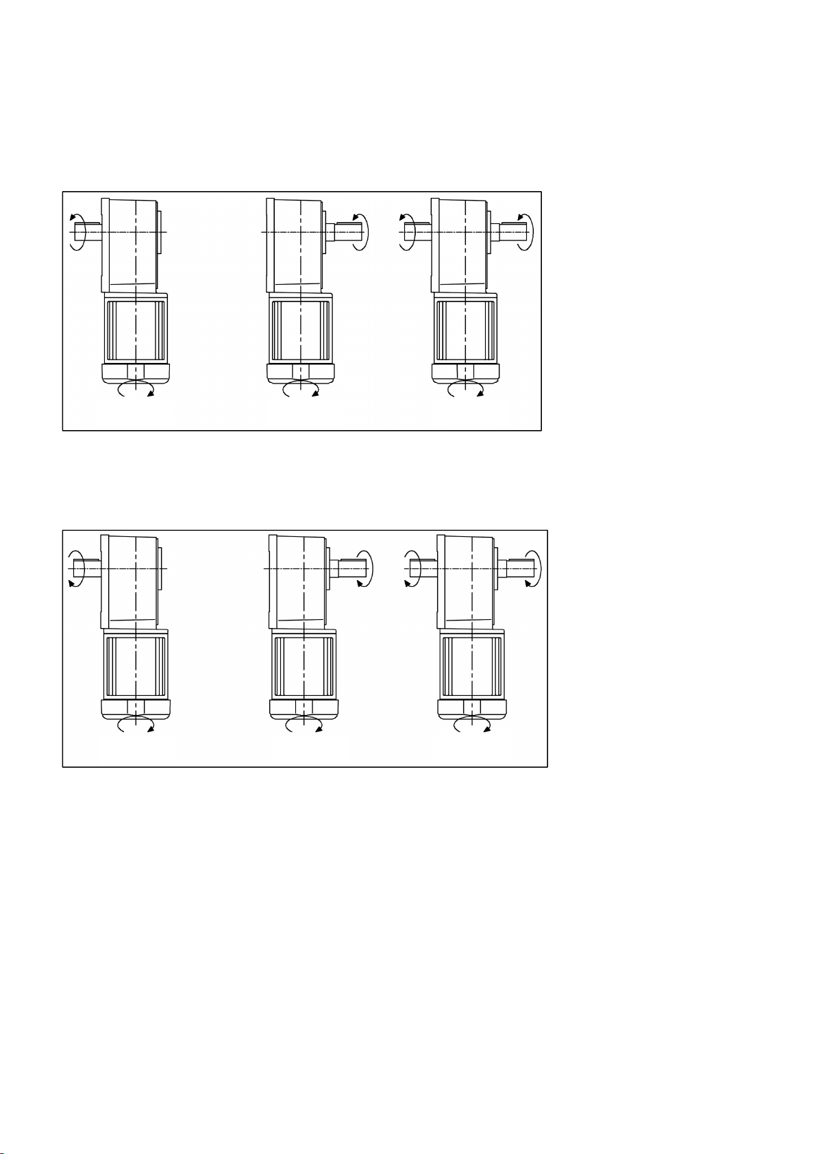
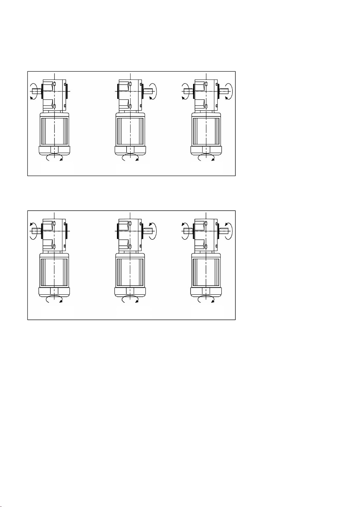
The relationship between the input shaft (motor) and the output shaft rotational direction
of this product are as follows.
The following rotational direction is the rotation when “6. Wiring.” is connected as normal rotation.
■For G3 Series
0.1kW
1/5 〜 1/50 and 1/300 〜 1/1200
0.2〜2.2kW
1/5 〜 1/30 and 1/300 〜 1/1200
0.1kW
1/60 〜 1/200
0.2〜2.2kW
1/40 〜 1/200
5.Rotational Direction
CAUTION
Check the direction of rotation before the gearmotor is connected to the application. A
difference in rotational direction may cause injury and/or damage to the application.
17
■For H2 Series
0.1・0.2kW
1/5 〜 1/60 and 1/600 〜 1/1500
0.4〜0.75kW
1/5 〜 1/60 and 1/300 〜 1/1500
1.5・2.2kW
1/5 〜 1/30
0.1・0.2kW
1/80 〜 1/450
0.4〜0.75kW
1/80 〜 1/240
1.5・2.2kW
1/40 〜 1/240
L Shaft R Shaft T Shaft
L Shaft R Shaft T Shaft
18
■For F Series
0.1〜0.75kW
1/5 〜 1/60 and 1/300 〜 1/1500
1.5・2.2kW
1/5 〜 1/30
0.1〜0.75kW
1/80 〜 1/240
1.5・2.2kW
1/40 〜 1/240
L Shaft R Shaft T Shaft
L Shaft R Shaft T Shaft
19
■For F3 Series
0.1〜2.2kW
1/5 〜 1/60
0.1〜1.5kW
1/80 〜 1/240
2.2kW
1/80 〜 1/120
L Shaft R Shaft T Shaft
L Shaft R Shaft T Shaft
20
This manual suits for next models
4
Table of contents
Other Nissei Engine manuals


