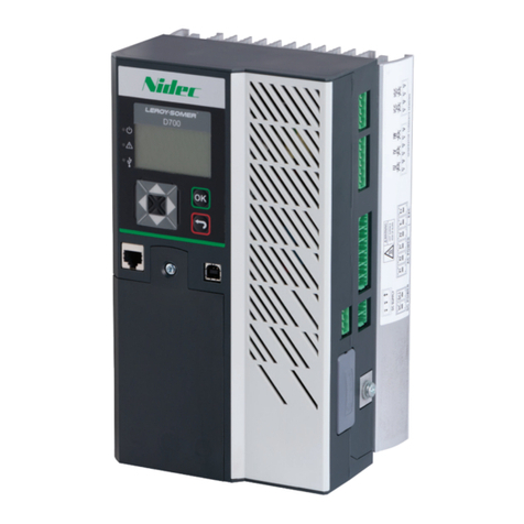
Nitek VR448 User manual

VR448
Generator Automatic Voltage Regulator
Operation Manual
Permanent Magnet Generator or A.R.E.P or Auxiliary Winding Type
Compatible with Leroy Somer R448*
* Use for reference purpose only and not a genuine Leroy Somer product.

___________________________________________________________________________________________
2VR448
NOTICE
1. This AVR may be installed in any suit-
able location on the generator set. The ap-
pearance and mounting holes are shown in
Figure 1.
2. To ensure safety and avoid permanent
damage to the AVR caused by high voltage,
be sure to remove the wiring on the AVR be-
fore using meg-ohm meter / high voltage
test equipment.
3. Be sure to tie up the connection wiring of the
AVR when installing in a high-vibration
environment. The heat sink may become
hot and could damage the wiring.
SECTION 1: SPECIFICATION
Sensing Input (E1、E2) Average Reading Voltage Regulation
Voltage 95 520 Vac 1 phase 2 wire Less than +/- 0.5% ( with 4% engine governing )
DIP Switch Settings
Adjustment 95 140 Vac @ 110 Vac Typical System Response
170 260 Vac @ 220 Vac 0.3 1 seconds @ +/- 20% Voltage Vibration
340 520 Vac @ 380 Vac
Frequency 50/60 Hz Jumper selected Static Power Dissipation
Max. 4 watts
Power Input (X1、X2)
Voltage 40 150 Vac 1 phase 2 wire Under Frequency Protection
Frequency 40 500 Hz 50 Hz system knee point at 45Hz
60 Hz systems knee point at 55Hz
Auxiliary Input (Z1、Z2)
Voltage 40 150 Vac 1 phase 2 wire Over Excitation Current limitation
Frequency 40 500 Hz 3.5A to 10A (EXC.MAX. Adjustable)
Excitation Output (E+、E-) Voltage Thermal Drift
120V 1 phase Continuous 110 Vdc 7A Less than 3% from -40 to +70 °C
Max. 160 Vdc 10A 10Sec
Resistance Min. 15Ω, Max. 100Ω@120V Environment
Fuse Spec. Slow blow 5 x 20mm 10A Operation Temperature -40 to +70 ˚C
Storage Temperature -40 to +85 ˚C
External Voltage Adjustment (1KΩ) Relative Humidity Max. 95%
Max. +/- 10% @ 1 KΩ 1 watt potentiometer Vibration 5.5 Gs @ 60 Hz
Quadrature Droop Input (S1、S2) Dimensions
CT N:1A 203.0 (L) x 153.0 (W) x 60.5 (H) mm
Sensitivity +/- 7%@ PF +/- 0.7 (STAT. Adjustable) 7.99 (L) x 6.03 (W) x 2.38 (H) inch
Build Up Voltage Weight
5 Vac 25Hz residual volts at power input terminal 850 g +/- 2%
1.874 lb +/- 2%
Soft Start Ramp Time
3 seconds +/- 10%
SECTION 2: DIMENSIONS
[5.51"]
140.0
[2.95"]
75.0
115.0
[4.53"] 100.0
[3.94"] [7.87"]
200.0
[2.36"]
60.0
Unit : mm
[0.71"]
18.0
[inch]
M5 L30
Figure 1. Outline Drawing

___________________________________________________________________________________________
EA448B 3
SECTION 3: DIP SWITCH SETTINGS
4050 (50)(60)
S F
J1
J1
1 2 3 J2
1 2 3 J2
X1、X2:Power Input
Connect working voltage, Max. 150Vac
Z1、Z2:Auxiliary Power Input
Connect Auxiliary voltage, Max. 150Vac
50Hz、60Hz:Frequency Selection
E+、E-:Excitation Output
Connect to generator excitation field
E1、E2:Sensing Input
Connect sensing input voltage Max. 600Vac
Sensing Input Voltage Selection
1 OFF 2 OFF :110Vac (95~140V)
1 ON 2 OFF :220Vac (170~260V)
1 ON 2 ON :380Vac (340~520V)
S1、S2:Quadrature Droop Input
Connect to generator CT
1KΩ:External Voltage Adjustment
Connect to external 1KΩ potentiometer
Terminals must be shorted when not in used
3Ph.:Three Phase Sensing Input
Connect to Three Phase Sensing
Module
EXC.MAX.:Over Excitation Current Limiting
Excitation output will be turned off when excita-
tion current is over the setting value
Min. 3.5A, Max. 10A
V/Hz:Under Frequency Adjustment
Adjustment for Under frequency and LAM
knee point
STAB.:Stability Adjustment
Under no-load operation, slowly adjust the
STAB VR counterclockwise until the
voltage is unstable, and then adjust it
clockwise for about 1/5 circle
VOLT:Voltage Adjustment
Adjust Generator output voltage
Adjustment range can be set by DIP SW
STAT.:Quadrature Droop Adjustment
Adjust the ratio of the idle power to the
voltage drop, when used in parallel.
Adjustment range is 0% to 7%
J1 Connected:With LAM protection
LAM:When Generator is loading the Engine speed will be
reduced. When engine speed is lower than pre-set frequency
threshold (V/Hz knee point), AVR will reduce voltage in 13%
or 25% (set by J2). This will make the active power of loading
reduce 25% to 45%, until engine speed reaches pre-set value
once again then voltage will resume to normal value.
J1 Disconnected:Without LAM protection
When J2 1–2 is shorted:Drop ratio 13% in LAM voltage
When J2 2–3 is shorted:Drop ratio 25% in LAM voltage
LED:LED will illuminate when AVR in normal operation
ST1:Single Phase / Three Phase Sensing Selection
Shorted:Single phase sensing
Open:Three phase sensing (must use with Three Phase Sensing Module)
ST2:Response Time Selection
Shorted:Slow
Open:Fast
Select response time according to Stability adjustment
ST6:Instantaneous Compensation for Voltage
Shorted:For Generator less than 600 KVA
Open:For Generator greater than 600 KVA
ST7:Keep shorted
ST6
ST1
ST2
VOLT
STAB.
V/Hz
EXC.MAX.J1
J2
ST7
1 2 3
STAT.
X2
Z1
X1
Z2
E+
E-
E1
E2
50Hz 60Hz
LED
VR448

___________________________________________________________________________________________
4VR448
SECTION 4ː CONNECTION DIAGRAMS
X2 Z1 X1 Z2 E+ E- E1 E2
T1 T7 T2 T8 T3 T9
T4 T10 T5 T11 T6 T12
FIELD
60Hz
50Hz
S2
S1
3Ph.
STATOR : 12 wires (marked T1 to T12)
potentiometer
1k /1W
External
T1
T1 T7 T2 T8 T3 T9
T4 T10 T5 T11 T6 T12
AUX WINDINGSFIELD STATOR : 12 wires (marked T1 to T12)
X2 Z1 X1 Z2 E+ E- E1 E2
60Hz
50Hz
S2
S1
3Ph.
potentiometer
1k /1W
External
T1
Figure 2. Self-Excited (SHUNT)
Figure 3. Auxiliary and Harmonic Power Winding
T1 T7 T2 T8 T3 T9
T4 T10 T5 T11 T6 T12
FIELD STATOR : 12 wires (marked T1 to T12)
PMG
X2 Z1 X1 Z2 E+ E- E1 E2
60Hz
50Hz
S2
S1
3Ph.
potentiometer
1k /1W
External
T1
Figure 4. PMG Winding
ATTENTION!!
1. Improper setting of under-frequency protection could cause the output voltage of the unit to drop or become
unstable with changes in load. Avoid making any changes to the U/F setting unless necessary.
2. Terminal Specification:6.35mm (1/4 inch) Flagged Terminals
3. Use only replacement fuses specified in this user manual.
4. Appearance and specifications of products are subject to change for improvement without prior notice.
VR448 1K
VR448 1K
VR448 1K
