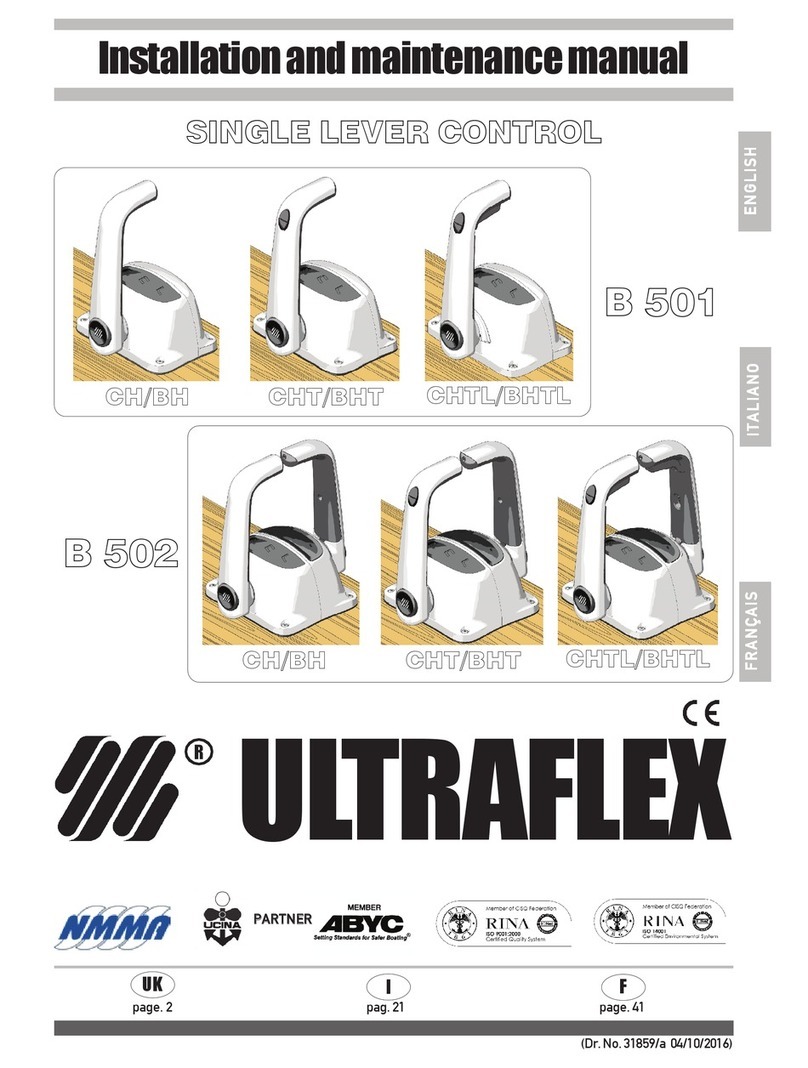
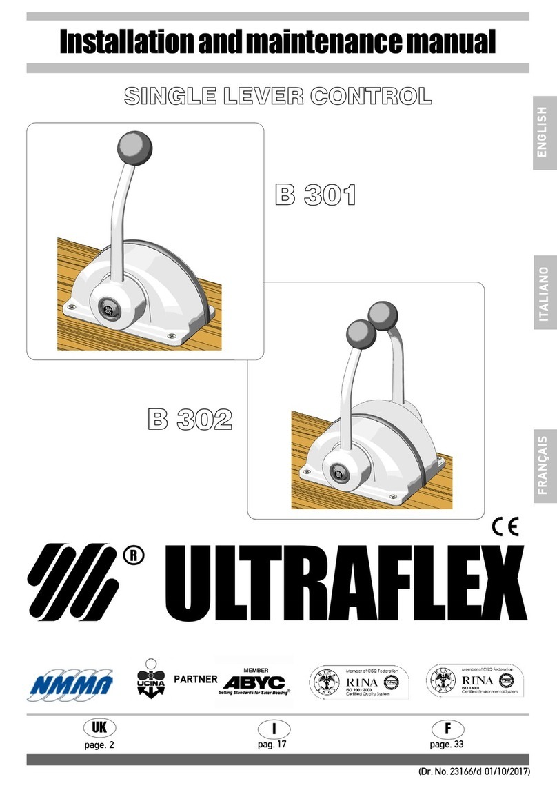
Ultraflex B505 Manual

ENGLISH
Installation and maintenance manual
SINGLELEVERCONTROL
®
ULTRAFLEX
Dis.36923
B505

ENGLISH
ULTRAFLEX
Dear Customer,
Thank you for choosing anULTRAFLEX product.
ULTRAFLEXhas been making steering and control systems for pleasure and working craft for many years.
ULTRAFLEXhas always been synonymous with reliability and safety.
All ULTRAFLEX products are designed and built to provide the best possible performance for the purpose for
which they were designed.
To protect your safety and maintain top quality, ULTRAFLEX guarantees its products only if they are used with
original parts (refer to “Application Spare Parts” annex).
ULTRAFLEX and UFLEX’s Quality Management Systems are CISQ-IQNet certified by DNV in accordance with
standard UNI ES ISO 9001:2008. ULTRAFLEX Certificate no. 6669/02/S (formerly 420/96). UFLEX Certificate no.
8875/03/S.
The Quality System gets all company resources and processes involved, starting with design, in order to:
- provide customers with a guarantee of product quality;
- identify actions for maintaining and improving quality standards with time;
- continually improve the efficacy and efficiency of processes in order to respond to the demands of the
market and improve customer satisfaction;
- ensure compliance with the requirements of directive 94/25 EC, standard ISO 10592 and ABYC (American
Boat Yacht Council) standards.
"With more than 85 years of experience in boatbuilding, ULTRAFLEX is a world leader in the production of
mechanical, hydraulic and electronic steering systems, control systems and steering wheels for motorboats
for pleasure, fishing or working uses, of all sizes and with all types of engines.
The reliability of our products and our pre- and post-sales service, the quality of our company’s organisation
and use of human resources and our ongoing investment in research and development are key factors in
explaining our products’ growing success all over the world”.
16015Casella(Genova)ItaliaViaCrose,2
ULTRAFLEX S.p.A.

Installation and maintenance manual
ENGLISH
ULTRAFLEX
6.1 Dismantling ................................................................................................................................. 15
TABLE OF CONTENTS
SECTION 1 PRODUCT DESCRIPTION
SECTION 2 INSTALLATION
SECTION 4 SAFETY WARNINGS
SECTION 5 MAINTENANCE
SECTION 6 DISMANTLING
1.1 Product description and recommendations for use ........................................................6
1.2 Dimensions and angles of the lever............................................................................................6
2.1 Tools required................................................................................................................................8
2.2 Installation of the control on the dashboard................................................................................8
2.3 Detent and clutch adjusting..........................................................................................................9
4.1 Safety during installation and use ............................................................................................ 13
4.2 Clothing ........................................................................................................................................ 13
5.1 Ordinary maintenance ................................................................................................................ 14
5.2 Special maintenance .................................................................................................................. 14
Use of this manual and symbols ......................................................................................................... 4
Note ......................................................................................................................................................... 5
Warranty ................................................................................................................................................. 5
(TO BE DIFINED) ................................................................................................................................... 17
TROUBLE SHOOTING
SECTION 3 CUSTOMIZABLE SYSTEMS
3.1 Throttle sensor..............................................................................................................................10
3.1.1 CAN BUS Throttle sensor..................................................................................................10
3.1.2 Voltage Throttle sensor.....................................................................................................10
3.2 Trim switch - Neutral safety lock................................................................................................11
3.2.1 Trim switch..........................................................................................................................11
3.2.2 Neutral safety lock..............................................................................................................11
3.3 Keyboard........................................................................................................................................12

Installation and maintenance manual
ULTRAFLEX
ENGLISH
page 4 of 15 B505
Immediate damage CAUSING serious injury or death.
DANGER
Operations which should be performed by qualified or specialized
personnel to avoid risks are identified by the symbol shown here.
Provide the personnel who will be installing the product with
appropriate training and make sure that they understand and
implement the instructions provided.
Information considered important for adequate installation and
maintenance which cannot cause damage.
USE OF THIS MANUAL AND SYMBOLS
THE INSTALLATION AND MAINTENANCE MANUAL is the document coming with the product from sale to
replacement and disposal, and should be considered an integral part of the product. Read the manual before
undertaking ANY ACTIVITY involving the product, including movement and unloading from the vehicle on
which it is delivered.
In order to protect the user’s safety and guarantee correct functioning of the product, this manual uses the
symbols described below.
Damage or unsafe practices which COULD lead to serious injury or
death.
Damage or unsafe practices which COULD lead to minor injury or
damage to the product or to property.
NOTE
IMPORTANT
WARNING

Installation and maintenance manual
ENGLISH
ULTRAFLEX
B505 page 5 of 15
NOTE
This installation and maintenance manual constitutes an integral part of the product and must be made
easily accessible for personnel using the product and performing maintenance work on it.
ULTRAFLEXshall not be held liable for any inaccuracies due to printing errors contained in the manual.
Without altering the basic features of the product described, ULTRAFLEX reserves the right to make any
changes to descriptions, details and illustrations that it may consider appropriate for its improvement or for
manufacturing or commercial reasons at any time, without being required to update this publication
immediately.
ALL RIGHTS RESERVED. Rights to publication, trademarks, logos and photographs of ULTRAFLEX products
present in this manual are the property of ULTRAFLEX and may not be reproduced in full or in part. Great care
has been taken to collect and verify documentation to make this manual as complete and easy to understand
as possible. None of the information contained in this publication may be interpreted as a guarantee or an
express or implicit condition – including, but not limited to, the guarantee of suitability for a particular
purpose. None of the information contained in this publication may be interpreted as a change to or
assertion of the terms of any contract of purchase.
The product must be installed by experienced personnel to ensure correct functioning of the product and its
components. In the event of breakage of components or malfunctioning, please contact specialized
personnel or our Technical Assistance Service.
WARRANTY
ULTRAFLEX warrants that its products are built according to the standards of good workmanship and are free
of defects in materials or workmanship.
This warranty is valid for two years starting on the date of manufacture, with the exception of cases in which
products are installed and used on working vessels or on vessels for commercial use, in which case the
guarantee is limited to 1 year from the date of manufacture.
This warranty is limited to free replacement or repair of the item, which must be returned freight paid,
provided we find it to be effectively defective in materials and/or workmanship.
The warranty does not cover any direct or indirect damages. The warranty specifically does not cover, and
we shall not be held liable for (except for replacement or repair of defective items under the terms and
conditions set forth above), malfunctioning of our products if their failure or poor functioning is due to
incorrect installation or to negligent or improper use.
This warranty does not cover products installed on racing boats or used in a competitive context. The
descriptions and illustrations in this manual are indicative only.
Please contact our Assistance Service for more detailed information.
The components of ULTRAFLEX steering and control systems are marked as required by directive 94/25/EC
and conform to ABYC standards (U.S.A.).
Note that on EC marked vessels it is obligatory to install steering and control systems with EC marked
components. (See Art. 3 and Art. 5 of directive 94/25/EC.) Note that the ULTRAFLEX warranty shall be
automatically forfeited if anyULTRAFLEX components are installed in a steering and control system along with
products of other brands.
IMPORTANT

Installation and maintenance manual
ULTRAFLEX
ENGLISH
page 6 of 15 B505
1 PRODUCT DESCRIPTION
1.1 Product description and recommendations for use
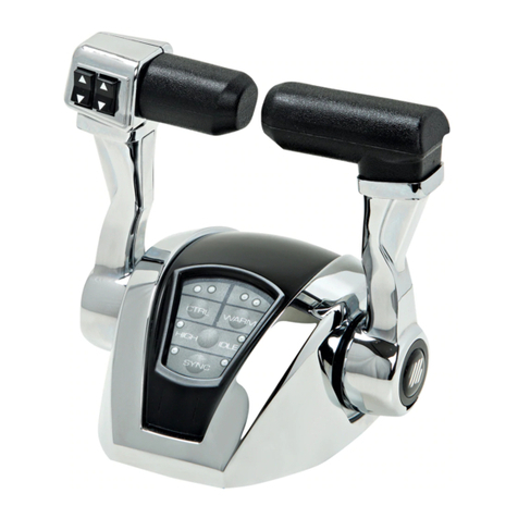
The lever control is assembled on the dashboard close to the vessel’s helm. The lever has an adjustable
clutch and the neutral detent has an adjustable detent force.
The B505 has the possibility of many customizations. See the chart 3.
1.2 Dimensions
The figure below shows the overall dimensions of the B505 control.
Make sure that the lever can turn freely and its travel is not blocked by obstacles on the dashboard.
NOTE
1.2 Dimensions

Installation and maintenance manual
ENGLISH
ULTRAFLEX
B505 page 7 of 15
The figure below shows the stroke angles of the B505 control.

Installation and maintenance manual
ULTRAFLEX
ENGLISH
page 8 of 15 B505
2
1Refer to the footprint dimensions given in point 1.2 to check that the control can effectively be installed
in the desired position. Install the mechanism after connecting the wiring if you have not access to the
bottom of the control when installed. Take care not to damage the sensor during installation.
After determining the appropriate location, cut the hole required to install the control using the
template provided.
2 INSTALLATION
Phillips screwdriver (ø4)
and flat-tip screwdriver (ø6)
Dispose of packaging in accordance with the law.
WARNING
Ellen Wrench (Ø3)
Ellen Wrench (Ø4)
2.1 Tools required
2.2 Installation of the control on the dashboard

Installation and maintenance manual
ENGLISH
ULTRAFLEX
B505 page 9 of 15
To change the load on the neutral detent, at first you have to shift the side cover (right to the keyboard)
downward to dismount it. Now you have access to the hole in which you can find a threaded screw. Use an
allen wrench (Ø4) to regulate it, untill you find the desired neutral detent force. Turn it clockwise to risen
the force on the detent, turn counterclockwise to lower it
To change the clutch load on the lever, at first you have to shift the side cover (left to the keyboard)
downward to dismount it. Now you have access to the hole in which you can find a threaded screw. Use
an allen wrench (Ø3) to regulate it, untill you find the desired clutch force. Turn it clockwise to risen the
force on the clutch, turn counterclockwise to lower it
2
1
2.3 Detent and clutch adjusting
2
1

Installation and maintenance manual
ULTRAFLEX
ENGLISH
page 10 of 15 B505
3.1.1 CAN BUS Throttle Sensor
The B505 lever can install the CAN BUS Throttle sensor. This kind of component can be programmed by
ULTRAFLEX with the technical caracteristics requested by the Customer. It is possible to modify the feeling, the
throttle curve and the reactivity. This will allow the communication between the system and the engine.
Contact our Technical Assistance Service to customize the CAN BUS sensor.
A wrong connection can cause serius injuries due to unespected starting of the engine
IMPORTANT
3.1 Throttle Sensor
The B505 lever has the possibility to install two different throttle sensors: the first with CAN BUS output,
the second one with output voltage.
3.1.2 Voltage Throttle Sensor
The B505 lever can install the Voltage Throttle sensor. In this case, the output is a tension in a range between
the 0.5V to 4.5V. It is possible to modify the Throttle curve, the feeling and the reactivity of the lever.
Contact our Technical Assistance Service to customize the Voltage sensor.
A wrong connection can cause serius injuries due to unespected starting of the engine
IMPORTANT
Throttle Sensor
3 CUSTOMIZABLE SYSTEMS

Installation and maintenance manual
ENGLISH
ULTRAFLEX
B505 page 11 of 15
If the B505 lever has the Trim switch, it is possible command the position of the Trim Tabs on the stern of
the boat.
3.2 Trim Switch Neutral Safety Lock
The B505 can be supplied with the Trim Switch or the Neutral Safety Lock underneath the handle.
3.2.1 Trim Switch
The B505 lever can install the Neutral Safety Lock instead of the Trim Switch.
3.2.2 Neutral Safety Lock
The Trim Switch has three positions:
- Top: move up the blades on the stern of the boat
- Center: the blades remains into the position desired
- Bottom: move down the blades on the stern of the boat
The top and the bottom positions are temporary positions.
Trim Switch
Neutral Safety Lock
This system locks the lever in the neutral position to avoid moving the lever accidentally. If the lever comes
back into the neutral position, the neutral safety lock will block the lever automatically.
A wrong connection can cause serius injuries.
IMPORTANT

Installation and maintenance manual
ENGLISH
ULTRAFLEX
B505 page 12 of 15
3.3 KEYBOARD
The B505 lever has got a keyboard in the rear side. It has three rubber button integrated in the styling of the
lever.
The keyboard has three normally open switch inside. A wrong connection can cause serius injuries.
IMPORTANT
Buttons are simple ON/OFF inputs signals. Buttons can be personalized or left black.
ULTRAFLEX can modify the labels on it depending to the customer request.

Installation and maintenance manual
ENGLISH
ULTRAFLEX
B505 page 13 of 15
4 SAFETY WARNINGS
This section shows the safety regulations to be applied for proper use of the apparatus. Read this section
very carefully and also read the manuals supplied with other components of the single lever control.
4.1 Safety during installation and use
PLEASE FOLLOW CAREFULLY the precautions and safety criteria indicated below.
ULTRAFLEX shall not be held liable for the user’s failure to observe these precautions and criteria and shall not
be held liable for any negligence in use of the system.
- NEVER PUT YOUR HANDS BETWEEN MOVING PARTS
- Do not desactivate safety devices or make them non-operative.
- Do not modify the system or add devices to it without written authorization or the intervention of an
ULTRAFLEXtechnician describing the change made in the description of the work performed.
- Do not use the apparatus for any purpose other than its intended use as specified in the
installation and maintenance manual.
- Do not allow untrained personnel to perform installation.
- During installation of the system, take particular care to keep everything clean to ensure that no
foreign bodies can get into the system. Even a tiny object can cause permanent damage which may not
be immediately obvious.
- Do not let wires come into contact with sharp corners or edges.
- Do not let wires come into contact with heat sources.
4.2 Clothing
DO NOT wear necklaces, bracelets or any loose garments that could get caught in moving parts during
installation, inspection or maintenance work.
DANGER
IMPORTANT
IMPORTANT

Installation and maintenance manual
ULTRAFLEX
ENGLISH
page 14 of 15 B505
5 MAINTENANCE
5.1 Ordinary maintenance
Failure to apply maintenance controls may result in loss of control when driving, which can result in damage
to property and/or injury.
Maintenance requirements will vary depending on climate and frequency and type of use. Inspections must
be conducted at least every two years by an experienced marine technician.
Perform the following maintenance operations:
- Periodically wash components with fresh water and remove any salt deposits.
- Once a month, check all nuts holding the system in place and tighten if necessary.
Loosening or separation of nuts holding the system in place can cause not only malfunctioning of the control
but damage or injury.
- Periodically check that there is no corrosion on metal parts of the cable terminals or abrasion on the
sheath.
- Replace damaged parts that may compromise the integrity of the control.
5.2 Special maintenance
Technical assistance
For any information or assistance with particular applications, you are invited to contact our technical
assistance service (refer to “Note”).
IMPORTANT
DANGER

Installation and maintenance manual
ENGLISH
ULTRAFLEX
B505 page 15 of 15
6 DISMANTLING
6.1 Dismantling
If you intend not to use the single lever control system any more, dispose of it in an environmentally sound
way.
Sheaths, hoses and components made of plastic or other non-metallic materials must be dismantled and
disposed of separately.
Table of contents
Other Ultraflex Controllers manuals