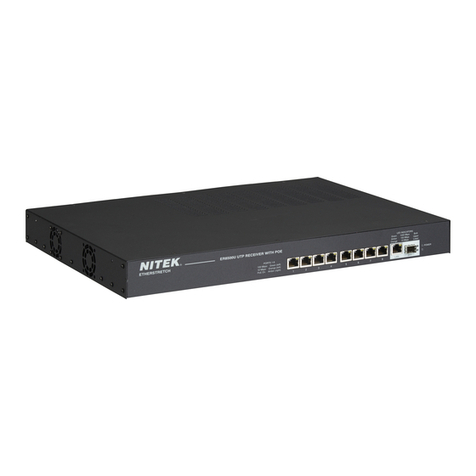
Nitek EtherStretch ER8500C User manual

Installation and Operation Manual
For Models ER8500C and ER16500C
IMPORTANT SAFTY INSTRUCTIONS
●Read all safety instructions.
●Keep these instructions.
●Heed all warnings.
●Follow all instructions.
●Do not use this apparatus near water.
●Clean only with a dry cloth.
●Refer all servicing to qualified service personnel.
●Install in accordance with the manufacturer’s instructions.
●Do not install near any heat sources such as radiators, heat registers, stoves or other appara-
tus that produce heat.
Patent Pending USA and Europe
Euro Pat App 2779641
NITEK®
De Aar 99
8253 PN Dronten
The Netherlands
Tel: +31(0) 321 310 043
WWW.NITEK.NET
USA
5410 Newport Drive, # 24
Rolling Meadows, IL 60008
Phone: (847) 259-8900
Fax: (847) 259-1300
WWW.NITEK.NET
EUROPE
12182014
681200113
Reduce risk of fire or electrical shock. Do not expose this product
to rain or moisture.
This installation should be made by a qualified service person and
conform with local codes.

2) Connect up the coaxial outputs of the unit. The coaxial ports are designed for connection with 75 ohm solid copper
coaxial cable, commonly RG-59 or RG-6. The coaxial port is a 100Mb network port. It is important that the coaxial
connectors be in good condition. The speed of the connection and POE status is indicated on the front panel of the
unit. A transmitter must be connected to the other end of the coaxial cable for the connection speed to be indicated
and for the POE to turn ON.
Head-end Installation
ER8500C and ER16500C
1) The ER8500C / ER16500C can be rack mounted, wall mounted or used as desk top unit. Use the included mounting
ears in the front or back of the unit depending on your needs. The mounting ears can also be turned to the bottom of
the unit for wall mounting if needed. When mounting the unit, be sure to follow these guide lines.
a. Operating Ambient - Do not install the unit in an assembly where the ambient temperature could exceed 52°C
(125°F). NOTE: the ambient temperature in a closed or multi-unit rack assembly could greatly exceed the ambi-
ent temperature outside that assembly.
b. Air-Flow – Leave space on the sides of the unit for airflow into the cooling fans and some space on top of the
unit for air to exit the unit. Adequate air flow is required for safe operation.
c. Mechanical Loading – The mounting ears were designed for two ears to support one unit. Other configurations,
such as mounting other equipment directly on top of the unit or using only one mounting ear, could cause a haz-
ardous condition due to uneven or excessive mechanical loading.
d. Circuit Loading - Do not connect the unit to an electrical supply if the wiring or over current protection of the sup-
ply could be overloaded when the ratings listed on the unit are considered.
e. Grounding (Earthing) - Reliable earth grounding of rack-mounted equipment should be maintained, use only 3
conductor equipment power cords. If the unit is plugged into a power strip or extension cord, that strip or cord
should have a ground (third) pin on its plug.
Front
Back
Rack Mounting
Options Wall Mounting
Options
SFP Ports
LAN Ports
Coaxial
Network Ports
Power Jack

3) Connect the LAN port to the network switch. The LAN ports of the ER8500 / ER16500 can communicate at 1Gbps.
The LAN port will automatically sense the connection speed of the connected network device. The LAN port is NOT
POE capable, only the coaxial ports can provide power to connected devices. The LAN jack of the ER8500 /
ER16500 will gather data from the coaxial ports and combine it into the higher speed LAN ports. The ER16500 is a
Layer 2 switch with 2 LAN ports. For most applications using a single LAN port, which provides a gigabit of band-
width, will be the easiest and best solution. Also commonly done is to use the additional LAN port to chain two or
more ER16500 units together. This will provide a way to bring 32 cameras or more into a single NIC of a NVR unit.
Additionally you must be aware that in some more complex network configurations loops can be created. Such condi-
tions can cause data to cascade and therefore bring down a network. The ER16500 has special LED indicators to
inform you if this is occurring. If the Trouble LED is flashing slowly it will indicate that the network has a loop in it and
data is cascading. It is recommended to remove the second LAN jack if this occurs and see if the problem goes away.
The data speed for all connected ports is indicated on the front panel LED. Make sure your network switch can han-
dle the expected data (i.e. do not use a 100Mb network switch if you expect 300Mbps of data).
4) A main power outlet shall be installed near to the equipment and easily accessible. Connect main power to the
ER8500 / ER16500 using a proper IEC power cord. A power cord is supplied in the box with your ER8500 / ER16500
unit. Disconnect main power before removing cover.
5) After completing the installation of the Head-end equipment, the transmitter units must be installed at the camera/
remote end.
Front Panel LED Display
Data Transmission
speed detected per
port, 100Mb or 10Mb
PoE Signature has been
detected and PoE is
being sent to connected
IP device
LAN connectivity data
transmission speeds
Main Unit Power
Trouble Indicator LED
On Solid if internal temperature is too High
Flashing if Network Loop is detected
Port Numbers
12345678
9 10111213141516
LAN
100 Mbps
10 Mbps
1000 Mbps
100 Mbps
10 Mbps
POWER
TROUBLE
100 Mbps
10 Mbps
PoE
PoE

Transmitter-end Installation
ET1500C or ET4500C Units
6) At the camera location securely mount the transmitter.
7) Find the coaxial cable from the head-end and make sure it is properly terminated RG59 or RG6 (75 ohm type) solid
copper cable. Connect coaxial cable to the BNC jack of the transmitter. If the head-end unit is powered up it will
sense the connection of the transmitter unit and turn on the power. This will be indicated by the green POWER LED
on the “Network Port”. After about 15 to 30 seconds the green 10/100 (upper) LED at the “Coax Port” will turn-on to
tell you that the head-end has connected with the transmitter unit. The Ethernet device does not need to be con-
nected for the transmitter to communicate with the head-end.
8) Finally, connect an Ethernet device to the transmitter “Network Port”. If the device requires PoE power, the POE OUT
(lower) LED at the “Coax Port” will turn on followed by the LINK STATUS LED on the “Network Port”. The IP camera
or other Ethernet device should now be ready to operate. Continue installing the remaining transmitters as needed.
Connector LED OFF ON FLASHING
Network
Port
Power No power Power
Good
Link Status No Ethernet
Link Ethernet Link
Good
Link
Port PoE Out No PoE
Power Out PoE Power
Good
10/100 No Link 100Mb 10Mb
ET1500C LED INDICATORS
ET1500
IP Camera
Coax from
Head-end
Transmitter Hookup Diagram
Link Port
Network Port
PoE Device Power
RG59 Coax *
Distance Power at PoE Port
328ft/100m 21.7 watts
984ft/300m 18.2 watts
1312ft/400m 14.4 watts
1640ft/500m 12.2 watts
656ft/200m 21.7 watts
*Results with ER8500
Receiver and using RG59
SBC Type Cable with
20AWG Center
Connector LED OFF ON FLASHING
Network
Port
PoE Out No PoE
Power Out PoE Power
Good
Link Status No Ethernet
Link Ethernet Link
Good
Link
Port Power No Power Power
Good
10/100 No Link 100Mb 10Mb
ET4500C LED INDICATORS
ET4500C
IP1
IP2
IP3
IP4
IP Camera
Coax from
Head-end
4CH Transmitter Hookup Diagram
Link Port
4 Network Ports
IP Device
IP Device

Optional Hookup for High Power PoE Devices
ET1500C or ET4500C Units
9) In some cases the PoE device connected at the transmitter end needs more power than can be supported over a long
coaxial run. You can usually identify these cases by watching the POWER LED of the transmitter, located on the
“Network Port”. If the power light cycles ON for less then 1 second and then is off for 3 or 4 seconds when the PoE
device is connected, but it turns ON and operates normally without a PoE device connected, this would indicate you
are having a current limit problem.
10) You should first check the power requirements of the PoE device. Also check the length of the coaxial cable. The
POE POWER CHART on the previous page will indicate the maximum power available for your length of coax.
11) If the needed level of power is not available for the length of coaxial cable, alternate options are available. One
method is to directly power the transmitter with a 48VDC power supply as shown below (Nitek# PS48). When pow-
ered directly from a 48VDC supply the transmitter can deliver full 802.3AT power regardless of the coaxial cable
length plus an additional length of up to 100 meters of network cable.
Distance from
Network Port PoE Device Power
Available
33ft/10m 33 watts
328ft/100m 26 watts
Transmitter used as
PoE Injector*
*Results with 48VDC power to the
Transmitter optional Power Port
ET1500
PS48
IP Camera
Coax from
Head-end
48VDC Powered Transmitter Hookup Diagrams
Link Port
Network
Port
115 VAC
Optional
48VDC
Supply
48VdcPower
Supply
ET4500C
IP1
IP2
IP3
IP4
IP Device
115/230VAC
IP Camera
IP Camera
IP Camera
Coax from
Head-end
Link Port
Network
Ports

BROWSER BASED GUI – LOGIN PAGE
The ER8500C and ER16500C do not require a user setup or configuration in order to function. When using a single unit.
Multiple units do need to be configured to prevent IP address conflicts, which could occur. The Graphical User Interface
(GUI) provide access to additional features to provide for monitoring of the system and customizing of the settings.
In order to connect with the unit, connect an Ethernet port of a PC to any port of the ER8500/ER16500 unit. Go into the
network setting for your PC and set its address to 192.168.1.100 and a subnet mask of 255.255.255.0. The default IP
address of the ER unit is //192.168.1.1, enter the address of //192.168.1.1 into your Browser. The unit will display a login
screen below. The default login is Name; “admin” with not password.
After login you will come to the HOME screen shown below. The Home screen provides a look at some basic informa-
tion about your unit. From here you can see basic information about the status of each port, current firmware, IP ad-
dress, and MAC address among other things. There are no settings or controls on this page.

Next move to the Administrator settings with the ADMIN button. Here you can setup passwords and users. Only the
administrator can access this page. Begin by entering a new admin user password. The password can be up to 11 dig-
its; it is case sensitive and may include special characters. Remember to record the admin password, as it is the only
way to access the admin screen. After setting the new password you will be forced to login again using the new pass-
word. Return to the ADMIN screen and add users as needed.
Additional users can be assigned. User names can be up to 9 characters and a password can be up to 8 characters.
For each user you may also select additional rights. “Restricted” will only allow this person to see the Home screen
and the Log Out Screen. “POE On/Off” will allow a user to turn off power to individual transmitters and cameras and to
make system settings adjustments. This user can cycle camera power, adjust link speeds, and reset the unit.
“Firmware” will allow a user to upgrade the firmware and reset the unit. “Network” will allow a user to change network
settings for a unit.
Also available only in the ADMIN screen is the CLOCK button. This can be used to set the current time internal to this
unit only. Set the current time for the unit in this screen. There is a real time clock in the unit which is battery backed
up. It is unlikely that the battery would need to be replaced under normal use but if it did the battery type is a standard
CR1220. The battery must be replaced by a qualified service tech only.

Next would be setting up the network connection. Select the Network button. From within the network page you can
change the IP address of the unit and the subnet mask along with other settings. Remember once you change the net-
work address you will have to login again to the unit. If you have multiple units in one installation you will need a
unique IP address and host name for each unit. It will operate with a single host name but can cause confusion for a
network administrator. The IP address allows you to access the web interface.
Units are shipped from the factory with the most up to date firmware. Firmware is from time to time updated to add fea-
tures to the unit. These updates are mostly in the form of added features in this webpage section. Firmware updates
will be posted to the Nitek website at www.nitek.net and can be found under the support tab. In the home screen page
you can see what firmware version is loaded in you unit and when it was loaded. To update the firmware, down load
update to your PC. From the Firmware Update page browse to the update file location on your PC and click the
“Upload” button. Next, enter the verification code and select the “Verify and Program” button. When complete the Re-
sult will change to “programmed”. You will need to reset the unit in order the have the code take effect. Reverting to
Factory Installed Firmware will keep all user settings but will change to the original firmware.

The “Links” page is useful in seeing the connections between each of the ports and the connected device. From within
this page you can see the link speed for all ports that are operating. The speed will be displayed below each port and
in the row marked “Mbps”. The speed can be controlled for each of the link ports. It is selected in the “Speed” row. The
ports normally operate at 100Mbps but can be changed if a connected device needs a lower speed or if the cable is
degraded and causing errors at a higher speed. The speed of the LAN and SFP ports is determined by the connected
device. They are normally 1000Mbps but if connected to a lower speed device they will automatically match the speed
of the connected device.
The “Mode” is normally set to automatic. In this mode the system is always checking for communication between con-
nected devices. If there is no communication or a fault is determined the system will attempt to repair the connection.
In rare situations some cameras may not be communicating with the server or may not yet be properly setup. This can
lead to a false reading. In this rare case Mode may need to be set to DM (Discovery Mode) to allow for cameras to be
configured. Once the cameras are properly configured the setting can be returned to “Auto” (automatic). Mode can
also be set to OFF, this will disable the operation of this port.
Finally the State displays the status of the links. There is a transmitter unit at the other end of each coaxial cable run.
The transmitter in turn is connected to a camera or other Ethernet device. State can tell you if all of the devices are up
and working. If the state is “Down” then no transmitter is detected. This can be because there is no unit connected or
maybe the coax was damaged or cut. Once a transmitter is detected the state will become “New”. After a very short
period state will show “Test”, this means that a transmitter is connected and is in the process of startup. The transmit-
ter in turn attempts to connect to an IP device. If there is no IP device or if the device is not working for some reason
the state will be “Test” or “Retry”. This shows that the system is attempting to get an IP device up and working. If all
parts of the system are working properly the state will show “Up”. This tells you the communication is normal.

Selecting the POE button will display power information about each port. You can see current, voltage and power con-
sumed from each power. Additionally, you can disable POE power out any of the ports which will being the link down.
You can see the temperature for each port at the ER8500C/ER16500C end. In this screen you can also turn on all of
the POE ports or reset the whole unit is needed.
The Labels button takes you the screen where you can apply a custom label to the inputs. This label will be displayed
below the port number on the Home screen.
When finished with the web interface it is important to close your browser completely. Some browsers keep cookies
and will not fully disconnect until the browser is closed
Other manuals for EtherStretch ER8500C
1
This manual suits for next models
1
Table of contents
Other Nitek Switch manuals
Popular Switch manuals by other brands

Lantronix
Lantronix SESPM1040-541-LT Series Operation guide
Belden
Belden Hirschmann GREYHOUND GRS1042 user manual
LevelOne
LevelOne GEL-2670 24 GE + 2 GE SFP Quick installation guide

Moxa Technologies
Moxa Technologies TN-5305-T Quick installation guide
Roline
Roline 14025029 user manual
Fortinet
Fortinet FortiSwitch Rugged 424F POE quick start guide
