1-3
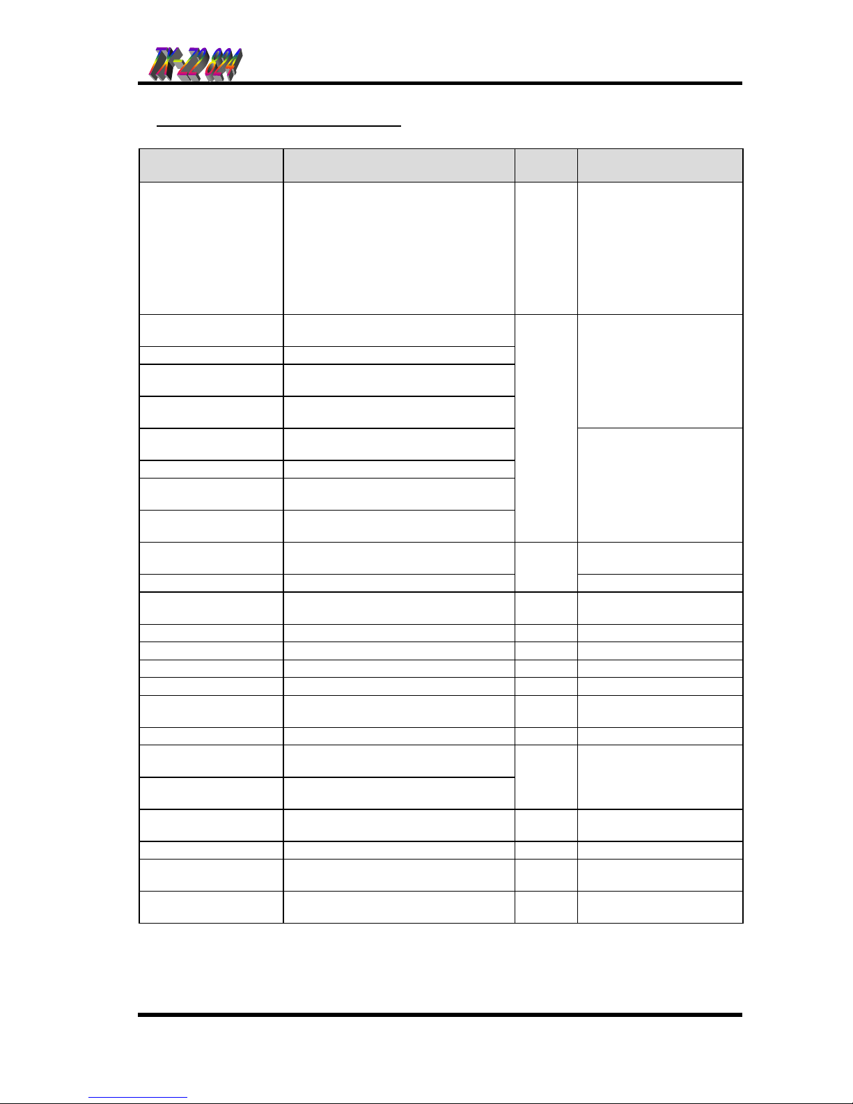
System Configuration
Name Description Quantity
/System Remarks
NX8E-824M. ME TX-Z2824 Main Equipment 1
CPU, Power Supply, battery
charger, Ringer for SLT, 4-
Trunk/8-extension interface,
1 power failure transfer
circuit for SLT,
EXMOH/BGM input and
SMDR or Local remote
programming interface
included.
NX.E-6TD TXZ KTS 6 Line keys, standard type Key
Telephone
NX.E-6TXD TXZ KTS 6 Line keys, display type Key Telephone
NX.E-12TD TXZ KTS 12 Line keys, standard type Key
Telephone
NX.E-12TXD TXZ KTS 12 Line keys, display type Key
Telephone
1st Model(Production
discontinue).
Modular station cable
included.
NX.E-6BTD TXZ KTS 6 Line keys, standard type Key
Telephone
NX.E-6BTXD TXZ KTS 6 Line keys, display type Key Telephone
NX.E-12BTD TXZ KTS 12 Line keys, standard type Key
Telephone
NX.E-12BTXD TXZ KTS 12 Line keys, display type Key
Telephone
24
2nd Model.
Modular station cable
included.
NX8E-208E-M1 2-Trunk/8-extension card With 1 power failure transfer
circuit
NX8E-008E-M1 8-extension card
2
NX8E-DHU-M1 2-Doorphone I/F, 2-relay contacts,
External Paging output 1
NX8E-VAU-M1 Voice Announce/ FAX transfer Card 1
NX8E-4CIDU-M1 Caller-ID interface Card (For 4 lines) 1 For mount to 408M unit
NX8E-2CIDU-M1 Caller-ID interface Card (For 2 lines) 2 For mount to 208E unit
NX8E-MODEMU-M1 Modem Card 1 *For Remote Programming
NX8E Remote
Programming Software Remote Programming Software 1
NX8E-ROMU-M1 Software Version Up 1 For version up the system
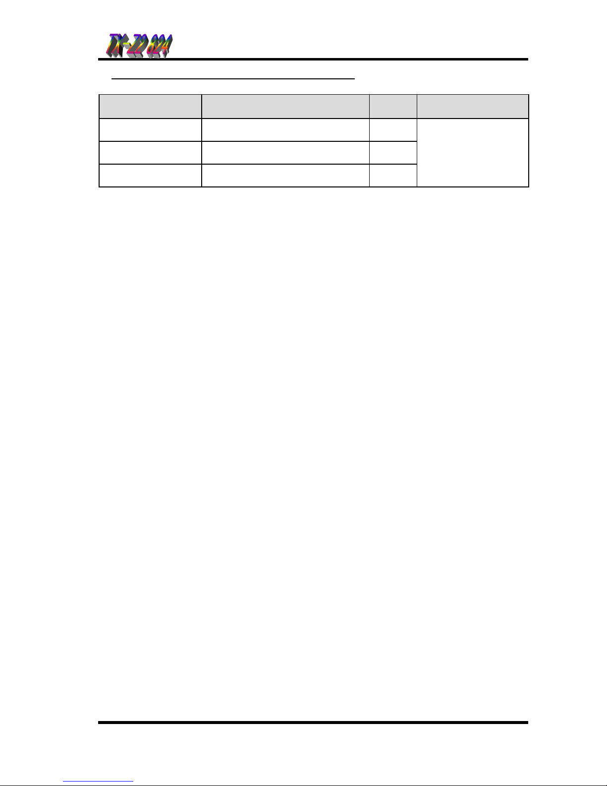
NX.E-24DL TXZ DLS 24 key DLS Console for 1st Model Key
Telephone (used as DSS Console)
NX.E-24BDL TXZ DLS 24 key DLS Console for 2nd Model Key
Telephone (used as DSS Console)
(1)
3
Connected to display type
key telephone.
NX7-24BDL W.M.K Wall mount bracket for 24BDL DLS As
needed
NT-S-D6 2-wire doorphone box 2 DHU-M1 is required.
Voice Mail I/F Voice Mail Interface Unit As
needed Required for VM connection
DX2E-32i/NX7E
BATTERY BOX External backup battery box 1 NP2.6 or equivalent
batteries are required.
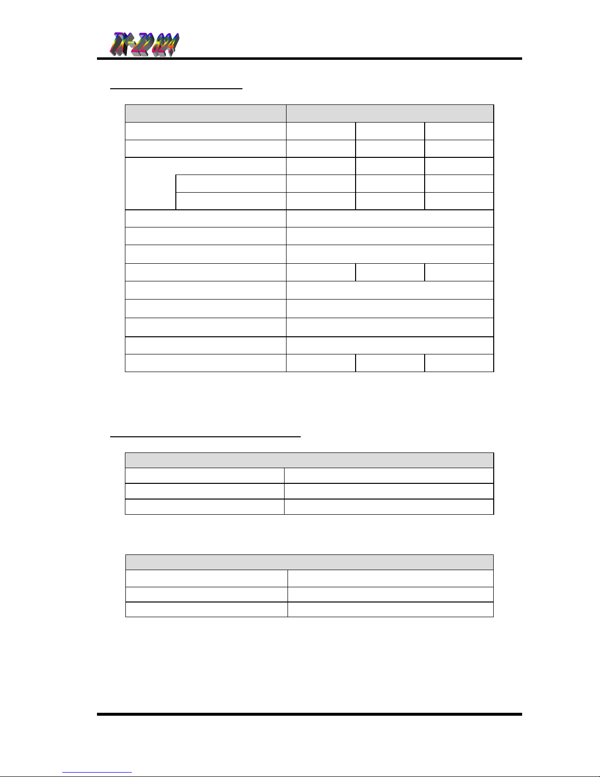
System Configuration
Part 1
:
::
:
Specification