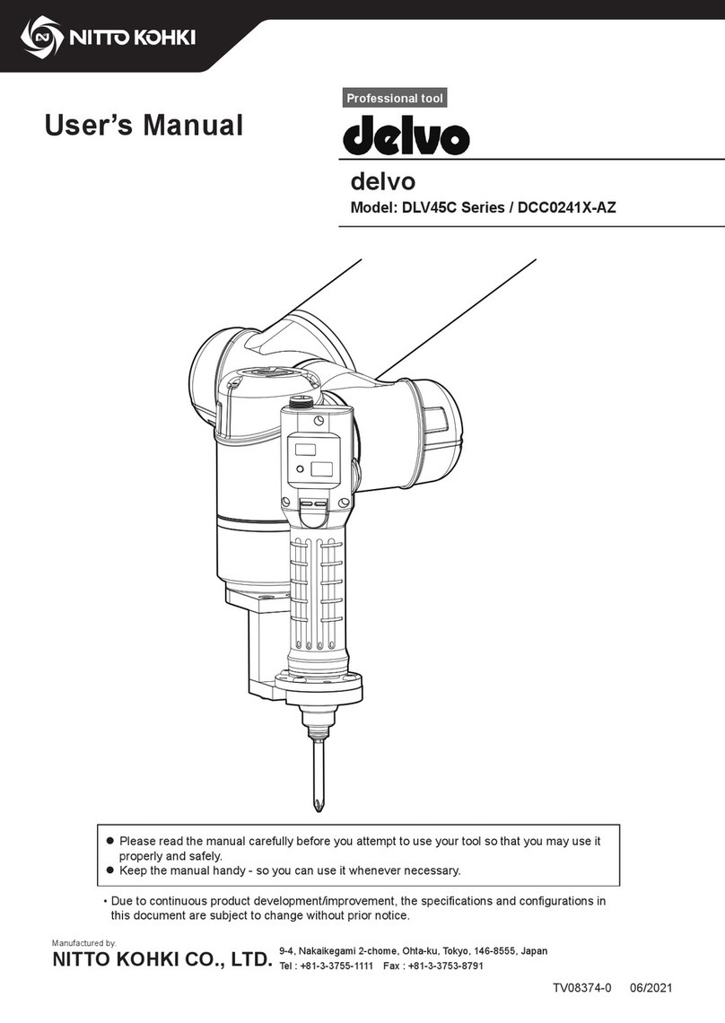
Nitto Kohki RC1000 User manual

INSTRUCTION
MANUAL
Professional tool REMOTE CONTROLLER
Model: RC1000
[Specifications]
Model
RC1000
Mass g (lbs) 110 (0.24)
(including 3 batteries that come with the controller)
Battery 3 Alkaline AAA Batteries
Service life
Continuous standby
hours 250 hours (Please refer to p. 8 for details.)
No. of times infrared light
is emitted 10,000 times (Please refer to p. 8 for details.)
Compatible electric screwdriver Refer to the attached “Electric Screwdriver Model List”.
ESD* protection Compliant with IEC61340-5-1
* ESD is the abbreviation of Electro-Static Discharge. It means the discharge of static electricity.
EN
This instruction manual is written in English.
Instruction manuals in other languages can be
downloaded from the URL below.
FR
Ce manuel d'instructions est rédigé en anglais.
Les manuels d'instructions dans d'autres langues
peuvent être téléchargés à partir de l'URL
ci-dessous.
DE
Diese Bedienungsanleitung ist auf Englisch verfasst.
Bedienungsanleitungen in anderen Sprachen können von
der unten genannten URL heruntergeladen werden.
IT
Il presente manuale di istruzioni è redatto in lingua
inglese.
I manuali di istruzioni in altre lingue possono essere
scaricati dal seguente URL.
ES
Este manual de instrucciones está escrito en inglés.
En la dirección URL indicada abajo se pueden descargar
los manuales de instrucciones en otros idiomas.
PT
Este manual de instruções está escrito em inglês.
Pode descarregar os manuais de instruções nos outros
idiomas a partir do URL indicado abaixo.
SC 本说明手册的语言是英文。
其他语言的说明手册可从以下 URL 下载。
http://www.nitto-kohki.co.jp/e/
Indoor Use Only
ESD Protection
Please read manual carefully before you attempt to use your tool so that you may use it properly and safely.
Keep the manual handy - so you can use it whenever necessary.
• Due to continuous product development/improvement the specifications and configurations in
this document are subject to change without prior notice.
Manufactured by.
NITTO KOHKI CO., LTD. 9-4, Nakaikegami 2-chome, Ohta-ku, Tokyo, 146-8555, Japan
Tel : +81-3-3755-1111 Fax : +81-3-3753-8791 (Original Instructions)
TV07529-1 07/2017
TV07529-1_RC1000_en.indb 1 2017/07/04 13:57:19

EN
Thank you very much for your purchase of this NITTO KOHKI product.
Before using your tool, please read this manual carefully so that you may use it properly to get the most out of it.
Please keep the manual handy - so you can use it whenever necessary.
Contents
IMPORTANT SAFETY INSTRUCTIONS.............. 1
General Power Tool Safety Warnings................... 1
Product Specific Safety Rules .............................. 4
1 Application ......................................................... 6
2 Checking Inside the Package............................ 6
3 Part Names........................................................ 7
4 Specifications .................................................... 8
Data transmission range.......................................8
5 Preparation........................................................ 9
Removing the packaging sheet.............................9
Attaching a battery................................................9
6 Basic Operation............................................... 10
Start ....................................................................10
Basic usage ........................................................10
Switching data receiving mode ...........................12
Initialization of settings........................................13
7 Settings............................................................ 14
MOTION settings ................................................14
FUNCTION settings...........................................16
8 Using Channel Patterns................................... 18
Registering channel patterns ..............................18
Canceling the channel pattern ............................19
Setting the electric screwdriver...........................20
Returning channel...............................................20
Connecting external signal..................................20
9 Remote Keylock .............................................. 22
10 Torque Check Mode ...................................... 23
11 Security Settings............................................ 24
Setting the password ..........................................24
Enabling the password........................................25
Disabling the password.......................................25
Entering the password ........................................26
12 Appendix........................................................ 27
Troubleshooting ..................................................27
Maintenance and inspection ...............................28
External dimensions............................................29
Screen display list...............................................30
Glossary..............................................................32
Index ...................................................................33
Setting memo......................................................34
TV07529-1_RC1000_en.indb 2 2017/07/04 13:57:19

1
EN
IMPORTANT SAFETY INSTRUCTIONS
Before using your tool, to avoid personal injury always take the basic precautions explained in later sections.
General Power Tool Safety Warnings
Personal safety
WARNING
Dress properly.
Do not wear loose clothing or jewelry. There is a
danger of being caught in moving parts. Wear a
pair of non-slip shoes. If your hair is long, wear a
protective hair covering to contain your hair.
Always wear eye protection.
Corrective glasses are not considered eye
protection. Always wear appropriate eye
protection.
Wear a dust mask.
When dust is generated in the workplace, always
wear a dust mask.
When loud noise is generated in the workplace,
always wear a hearing protection.
Do not overreach.
Keep proper footing and balance at all times.
Be on your guard when working.
Do not use a power tool when you are tired.
When you use the tool, be sure about the
handling method, how to work, and pay sufficient
attention to the surrounding environment.
Never touch the tip of moving parts when the power tool is running.
Also, do not direct the tip of moving parts toward people or animals.
Be aware of tool vibration and recoil. Some tools can cause a considerable amount of vibration.
Depending on how the product is operated, the type of tool setting, and the length of operation, it could place a
tremendous burden on your hands, arms and body.
The tool could cause a vibration injury or tendonitis. Avoid long-term use and take appropriate breaks.
Consult a doctor if you experience any discomfort or pain during operation.
Protective hair
covering
Dust mask
Work clothes
Safety shoes
Protective
goggles
Earplugs
TV07529-1_RC1000_en.indb 1 2017/07/04 13:57:19

2
EN
Work area safety
WARNING
Do not use the tool at home.
This is a professional tool (industrial or work tool for business). Do not bring the tool home and use it there.
Keep the work area clean.
Working in a messy work area or work table could cause an accident.
Be cautious about the work area.
Do not expose power tools to rain.
Do not use the tool in a damp or wet place.
Keep the work area well lit.
Do not operate power tools in an explosive atmosphere, such as in
the presence of flammable liquids (thinner, lacquer, gasoline, etc.)
or gas.
Do not let children come close to the work area.
Keep children and bystanders away while operating tool.
Some tools generate loud noise.
Check that the noise regulations of each area are complied with.
When work has to be done in high locations, make sure there is
nobody underneath the work area.
If the tool or material is dropped, it could cause an accident or
injury.
Before starting operation, make sure that there is no conduit,
water pipe or gas pipe by your work area.
If a tool touches a buried object, it could cause electrical shock or leakage, which could cause an accident.
Before starting to work
WARNING
Perform inspection before using the tool.
Before using the tool, check for loose screws on the tool and for damage on the protective cover or other parts,
and make sure that the tool operates normally and demonstrates prescribed functions.
Check the position adjustment and tightening status of moving parts, parts damage, attachment status, and all
other locations for issues that could affect operation.
For parts replacement and repair, follow the instructions indicated in the instruction manual.
If there are no instructions in the instruction manual, contact the retailer where you purchased the tool.
Do not use the power tool if the switch does not turn it ON and OFF.
Make sure to properly attach the tip tool.
If the tip tool is not attached properly, there is a risk of jumping out or damage, which could result in injury.
After adjustment, be sure to remove tools such as spanners, wrenches, etc.
Use appropriate tools.
Do not force small tools to do the job of a heavy duty tool. Do not use tools for purposes not intended.
Do not use tools in an unreasonable manner.
When the specifications are followed, tools can be used efficiently and safely.
Secure workpieces.
Where possible use clamps or a vise to hold the workpiece. It is safer than using your hand and both hands can
be used for operation.
IMPORTANT SAFETY INSTRUCTIONS
TV07529-1_RC1000_en.indb 2 2017/07/04 13:57:19

3
EN
Handling tools
WARNING
Storing the tool
When the tool is not used, store the tool in a dry location. Also, store the tool out of the reach of children.
For some tools, the storage temperature and humidity are specified. Store the tool in an appropriate location.
Be cautious about how the tool is carried.
Do not carry the tool with your hand touching the operation switch.
Do not leave the tool while the tool is still running.
Do not leave the work area until you turn off the operating switch, remove the power source and the tool
completely stops.
Do not allow the following chemicals to come into contact with the tool, as parts could deteriorate.
Acetone, benzine, thinner, ketone, ether, trichlorethylene and other similar chemicals
Maintenance and inspection
WARNING
Do not disassemble or alter the tool.
Using the tool after disassembling or remodeling it could cause an accident or injury.
Inspect tip tools and accessories.
Always inspect tip tools and accessories for damage or deterioration before attaching them to the tool.
If there is damage or deterioration, replace or request repair from the retailer where you purchased the tool.
Inspect for damaged sections.
Sufficiently check for damage on accessories or other parts, that the tool operates normally, and that work can
be performed appropriately.
If there are accessories or parts that have been damaged or could hinder work, request repair from the retailer
where you purchased the tool.
Request repair from a dedicated store.
For repair or part replacement, contact the retailer where you purchased the tool.
Repair requires special knowledge and skills. If repair is performed at a place other than a specialty store, the
tool may not demonstrate its full performance or it could lead to an accident or injury.
Request repair with the failed status kept intact. When requesting a repair, do not throw away damaged parts. It
could be important information for investigating the failure cause so do not change the status.
Use genuine parts.
If inappropriate parts are used, it could cause accident or injury.
Genuine parts are listed in the instruction manual or brochure. Contact the retailer where you purchased the tool.
Do not remove the label or nameplate on the tools.
If labels or nameplates are broken or peeling, for a replacement label or nameplate contact the retailer where
you purchased the tool.
TV07529-1_RC1000_en.indb 3 2017/07/04 13:57:19

4
EN
Product Specific Safety Rules
WARNING
Use the tools indoors.
This tool is not dust and leak-proof.
Exposure to dust, sand, or rain while using it outdoors could cause a failure.
Store alkaline batteries out of the reach of children.
Swallowing batteries could cause suffocation or could stay in the stomach, which is very dangerous. If suspected
to have swallowed a battery, immediately consult a doctor.
If the alkali solution of the alkaline battery leaks, do not touch with bare hands.
If alkaline solution gets into eyes, there is a risk of blindness. Do not rub the eyes and rinse with clean water and
then immediately consult a doctor.
If alkali solution adheres to the skin or cloth, skin problems could occur. Immediately rise with clean water. If
suspected to have skin problem such as inflammation, immediately consult a doctor.
Do not toss alkaline batteries into a fire or water or heat, disassemble or short-circuit batteries. Also, do not
perform direct soldering to batteries.
Fire or injury could be caused due to rupture of the battery or leakage of alkali solution.
Do not charge alkaline batteries.
Fire or injury could be caused due to rupture of the battery or leakage of alkali solution.
Do not remove or damage the outer label of alkaline batteries.
Doing so could cause overheating accidents.
Be careful about the plus (+) and minus (-) orientation of alkaline batteries and set correctly as indicated on the
device.
Incorrect orientation could result in fire or injury due to rupture of the battery or leakage of alkali solution.
Do not use batteries other than alkaline batteries. Also, do not use different types of batteries together.
Fire or injury could be caused due to rupture of the battery or leakage of alkali solution.
Do not use batteries after the recommended service life displayed on the alkali battery has elapsed.
Fire or injury could be caused due to rupture of the battery or leakage of alkali solution.
Do not mix and use old (already used) and new batteries together.
Fire or injury could be caused due to rupture of the battery or leakage of alkali solution.
When the battery is used up or not used for a long time, remove the alkaline batteries.
If batteries are left as is, alkali solution could leak and cause failure, fire, or injury due to overdischarge.
When the remote controller is not used, turn OFF the power. Or, remove the alkali battery.
If the tool is kept ON and the battery is left as is, alkali solution could leak and cause failure, fire, or injury due to
overdischarge.
If the tool is accidentally dropped or hit, check to ensure there is no breakage, cracking or deformation.
Breakage, cracking or deformation could cause electric shock or injury.
When the tool becomes overheated, or you notice anything abnormal during usage, switch it OFF immediately
and request that the tool be repaired.
CAUTION
Do not apply a shock (such as dropping) or excessive load to the LCD.
The LCD uses glass. When the glass cracks, it could cause electric shock or injury.
Be careful about storage in cold climates.
The LCD could be damaged due to condensation or freezing.
Do not apply a shock (such as dropping) or excessive load to the power supply switch and operation button.
Doing so could cause a failure.
Alkaline batteries are expendable parts. They are not covered under warranty.
The alkaline battery included in the package is used for checking initial operation. The service life of the battery
may be short. Use a new alkaline battery.
The security function is not a function to prevent theft.
We provide no warranty whatsoever that protects against the product being stolen.
IMPORTANT SAFETY INSTRUCTIONS
TV07529-1_RC1000_en.indb 4 2017/07/04 13:57:19

5
EN
CAUTION
Pay sufficient attention when handling the password.
Cancellation or extraction of passwords shall be paid services.
Be cautious about loss or failure.
There are functions provided to lock (remote keylock, security function) the electric screwdriver using a remote
controller. When the remote controller is lost or fails, the screwdriver may no longer be used due to those
functions. We recommend that you have a spare remote controller.
About Unit Notation
This instruction manual is written using both SI units and the imperial measurement method (yards, pounds).
Numeric values outside the ( ) are the value in SI units, while those inside the ( ) are the imperial measurement
value.
Notation Example: Length 25.4 (1") Weight: 0.45 (1) Torque: 1.13 (10)
About FCC/ISEDC
NOTE: This equipment has been tested and found to comply with the limits for a class B digital device, pursuant to
part 15 of the FCC Rules.
These limits are designed to provide reasonable protection against harmful interference in a residential installation.
This equipment generates, uses and can radiate radio frequency energy and, if not installed and used in
accordance with the instructions, may cause harmful interference to radio communications.
However, there is no guarantee that interference will not occur in a particular installation.
If this equipment does cause harmful interference to radio or television reception, which can be determined by
turning the equipment off and on, the user is encouraged to try to correct the interference by one or more of the
following measures:
- Reorient of relocate the receiving antenna.
- Increase the separation between the equipment and receiver.
- Connect the equipment into an outlet on a circuit different from that to which the receiver is connected.
- Consult the dealer or an experienced radio / TV technician for help.
This device complies with part 15 of the FCC Rules. Operation is subject to the following two conditions:
(1) this device may not cause harmful interference, and
(2) this device must accept any interference received, including interference that may cause undesired operation.
in
mm
lbs
kg
Lb·in
Nm
TV07529-1_RC1000_en.indb 5 2017/07/04 13:57:19

6
EN
1 Application
This is a remote controller used to set the electric screwdriver remotely using infrared communication.
2 Checking Inside the Package
When you open the package box, check the content of the package and also check for any damage caused by
incidents during transportation.
If a problem is found, consult with the store where you purchased the product.
Package content and list of accessories
Package content and accessories Quantity
Remote Controller (main unit) 1
Alkaline AAA battery 3
Instruction Manual (this book, Japanese) 2
Electric Screwdriver Model List 1
CAUTION
The alkaline battery included in the package is used for checking initial operation.
The service life of the battery may be short. Use a new alkaline battery.
TV07529-1_RC1000_en.indb 6 2017/07/04 13:57:20

7
EN
3 Part Names
1
2
3
5
4
6
7
8
9
0
Name Function
1Power supply switch Turns the power ON/OFF.
2[TRANSMISSION] button Press to send the setting data to the electric screwdriver.
3[SELECT] button Selects setting items.
4Infrared transmission unit Sends infrared light to the electric screwdriver.
5LCD screen Displays the settings and remote controller status.
6[UP] button Press to change settings.
7[RETURN] button Returns to the previous setting.
8[DOWN] button Press to change settings.
9[ENTER] button Finalizes the set item.
0Accessory attachment part Used to attach a tag or strap.
TV07529-1_RC1000_en.indb 7 2017/07/04 13:57:20

8
EN
4 Specifications
Battery level indicator
When the battery level becomes about half, a battery icon is displayed on the LCD.
The battery level is about half.
Data transmission becomes unstable. Replace the battery.
CAUTION
Continuous standby time and the number of times data is transmitted are the standard reference upon starting
to use a new battery.
Those hours and times vary depending on the frequency of button operation.
Continuous standby hours: Standard reference when the button is not operated and infrared light is
not emitted
No. of times data is transmitted: Standard reference on the condition that buttons other than data
transmission are not operated
Data transmission range
The standard range of data transmission from the device to the electric screwdriver is the following range and distance
from the front of the motion setting area of the electric screwdriver.
Switch the electric screwdriver to be set to data receiving mode. It is possible to set multiple screwdrivers at the same
time.
For operation of the electric screwdriver, refer to the instruction manual for the electric screwdriver.
P
TV07529-1_RC1000_en.indb 8 2017/07/04 13:57:20

9
EN
CAUTION
The range of data transmission is a standard reference.
The range changes depending on the ambient environment and battery consumption.
The back of the motion setting area, the top and bottom sides, and the sides of the electric screwdriver do not
respond.
When the battery level becomes low, the distance and range become narrower and response becomes dull.
Replace with a new battery.
If there is blocking material between the device and the electric screwdriver, the screwdriver may not respond.
Also, if the surrounding wall or ceiling is black, it may be difficult for the electric screwdriver to respond.
5 Preparation
Removing the packaging sheet
The packaging sheet protects the device from scratching until the device is delivered
to the customer. This sheet is not intended to protect the device from scratching during
use. Remove the sheet before use.
SELECT
REMOTE CONTROLLER
RC1000
ENTER
DOWN
UP
RETURN
TRANSMISSION
OFF
ON
SELECT
REMOTE CONTROLLER
RC1000
ENTER
DOWN
UP
RETURN
TRANSMISSION
OFF
F
ON
O
Attaching a battery
Remove the battery cover and insert alkaline batteries. Insert batteries in the correct orientation of + and -.
OPEN
TV07529-1_RC1000_en.indb 9 2017/07/04 13:57:20

10
EN
6 Basic Operation
Start
When the power switch is slid to the ON side, text is displayed on the LCD
and the device starts up.
When you finish using it, slide the power switch to the OFF side.
OFF
ON
ON
OFF
Basic usage
Use this device to make settings and send them to the electric screwdriver.
To prevent inadvertent operation, the device does not respond when you lightly press the buttons. Press the buttons
firmly. When a button is pressed, an electronic sound is emitted.
1 Turn ON the power switch of the remote controller
After the software version is displayed on the LCD, MAIN MENU is displayed.
2 Press the [SELECT] button to select MAIN MENU
Select from the following.
MAIN MENU Setting details Reference
MOTION Sets the content of “Motion setting mode”
of the electric screwdriver. p. 14
FUNCTION Sets the content of “Function setting mode”
of the electric screwdriver. p. 16
CH PATTERN Sets the order of channel switching. p. 18
KEYLOCK Sets keylock/unlock. p. 22
TORQUE CHECK For torque check, operates the electric
screwdriver at the final speed level. p. 23
SECURITY Sets the password to request the password
upon power ON of the electric screwdriver. p. 24
OFF
ON
0$,10(18
027,21
3 Press the [ENTER] button
TV07529-1_RC1000_en.indb 10 2017/07/04 13:57:21

11
EN
4 Select the [SELECT] button to select the setting item and press the
[ENTER] button
To return to the previous item, press the [RETURN] button.
OFF
ON
&+B6(/(&7
&+B
5 When is displayed on the LCD, use the [UP] button / [DOWN]
button to change the value
OFF
ON
67$57B63(('
/9B&+B
6 Use the [ENTER] button to finalize the value
The set value is saved.
Repeat Steps 4 to 6 to set each item.
7 Change the electric screwdriver to set to receiving mode
Change all electric screwdrivers to set to receiving mode. (p. 12)
Check that the main LED of the electric screwdriver lights in yellow.
8 While is displayed on the LCD of the remote controller, press
and hold the [TRANSMISSION] button
When the screwdriver starts receiving data, the main LED lights in blue and
when receiving is completed the LED flashes in blue.
OFF
ON
6(7830(18
527$7,21&+B
TV07529-1_RC1000_en.indb 11 2017/07/04 13:57:21

12
EN
Switching data receiving mode
Make all electronic screwdrivers to be set from the remote controller to data receiving status.
1 While the electric screwdriver is in screw fastening mode, press
and hold the [MEMORY] button and the [DOWN] button
Press and hold at the same time
The buzzer sounds, the main LED lights in yellow and the workpiece LED
goes off.
Data reception from the remote controller is awaited.
Pressing and holding the [SELECT] button cancels data receiving mode.
Lights in yellow
Lights off
Receiving data from the remote controller
When the data is sent to the electronic screwdriver from the remote controller, the main LED of the electric screwdriver
lights in blue.
When reception is successful, the main LED flashes in blue and the mode of the electric screwdriver returns to screw
fastening mode.
Receiving Received successfully
Lights in blue Flashes in blue
When reception fails, the main LED lights in yellow again to wait for data reception again.
Basic Operation
TV07529-1_RC1000_en.indb 12 2017/07/04 13:57:22

13
EN
Initialization of settings
It is possible to initialize settings of the remote controller to the factory default.
1 Turn OFF the power of the remote controller
2 While pressing the [TRANSMISSION] button and [DOWN] button,
turn on the power
Initialization completes and a beep sounds.
OFF
ON
TV07529-1_RC1000_en.indb 13 2017/07/04 13:57:22

14
EN
7 Settings
CAUTION
Always record the set values.You can utilize “Setting memo” (p. 34).
If the tool fails, all settings may be initialized. Also, settings may be initialized at the time of repair in order to
check operation.
Please note that there is no function to output the set values to an outside device.
MOTION settings
Using “MOTION” in MAIN MENU, you can set the content of “Motion setting mode”.
Setting is made for each channel.
The motion setting mode of the electric screwdriver and remote controller menu correspond as shown in the following
table.
For the details of each function, refer to the instruction manual for the electric screwdriver.
Motion setting mode of the electric screwdriver Setting of MAIN MENU “MOTION”
No. Function SETUP MENU (3rd layer) Setting items (4th layer)
1 Screw count SCREW SF NUMBER
2 Speed level at start ROTATION START_SPEED
3 Rotation time at start ROTATION START_TIME
4 Speed level at middle ROTATION MID_SPEED
5 Rotation time at middle ROTATION MID_TIME
6 Speed level at finish ROTATION FIN_SPEED
7 Lower limit of screw fastening time SCREW MIN_SF TIME
8 Upper limit of screw fastening time SCREW MAX_SF TIME
9 Auto reverse mode setting ROTATION AUTO REVERSE
10 Reverse speed level ROTATION REV_SPEED
11 Reverse rotation time ROTATION REV_TIME
1 Turn ON the power switch of the remote controller and check that
MAIN MENU is “MOTION” and then press the [ENTER] button
When it is not “MOTION”, use the [SELECT] button to switch the display.
“CH_SELECT” is displayed.
ON
0$,10(18
027,21
(1st layer)
2 Use the [SELECT] button to select “CH_1” to “CH_8”, or “CH_ALL”
and press the [ENTER] button
“SETUP MENU” is displayed.
When “CH_ALL” is selected, the procedure goes to Step 8.
ON
&+B6(/(&7
&+B
(2nd layer)
3 Use the [SELECT] button to select “ROTATION” or “SCREW” and
press the [ENTER] button
The set item is displayed.
ON
6(7830(18
527$7,21&+B
(3rd layer)
TV07529-1_RC1000_en.indb 14 2017/07/04 13:57:23

15
EN
4 Use the [SELECT] button to select the item to set
The following settings are available.
SETUP
MENU
Setting items
(4th layer) Function Setting range (default value)
ROTATION
START_SPEED Speed level at start LV_1 to LV_9 (LV_9)
START_TIME Rotation time at start OFF / 0.01 SEC to 9.9 SEC
(OFF)
MID_SPEED Speed level at middle LV_1 to LV_9 (LV_9)
MID_TIME Rotation time at middle OFF / 0.01 SEC to 9.9 SEC
(OFF)
FIN_SPEED Speed level at finish LV_1 to LV_9 (LV_9)
AUTO REVERSE Auto reverse mode setting OFF / TORQUE UP / TIME
(OFF)
REV_SPEED Reverse speed level LV_1 to LV_9 (LV_9)
REV_TIME Reverse rotation time OFF / 0.01 SEC to 9.9 SEC
(OFF)
SCREW
SF NUMBER Screw count 01_SCREW to 99_SCREW
(01_SCREW)
MIN_SF TIME Lower limit of screw fastening time OFF / 0.01 SEC to 9.9 SEC
(OFF)
MAX_SF TIME Upper limit of screw fastening time OFF / 0.01 SEC to 9.9 SEC
(OFF)
5 Press the [ENTER] button
appears on the LCD.
6 Use the [UP]/[DOWN] buttons to change the value and then use the
[ENTER] button to finalize the value
The set value is saved.
ON
67$57B63(('
/9B&+B
7 Set other items in the same way
To return to the previous item, press the [RETURN] button.
8 While is displayed on the LCD, press and hold the
[TRANSMISSION] button
The settings of the channel selected in Step 2 are sent collectively.
When “CH_ALL” is selected in Step 2, the settings of all channels are sent
collectively.
ON
6(7830(18
527$7,21&+B
TV07529-1_RC1000_en.indb 15 2017/07/04 13:57:23

16
EN
FUNCTION settings
Using “FUNCTION” in MAIN MENU, you can set the content of “Function setting mode”.
The function setting mode of the electric screwdriver and remote controller menu correspond as shown in the following
table.
For the details of each function, refer to the instruction manual for the electric screwdriver.
Function setting mode of the electric screwdriver Setting of MAIN MENU “FUNCTION”
No. Function SETUP MENU (2nd layer) Setting items (3rd layer)
1 Workpiece signal WORK WORK SIGNAL
2 Workpiece setup time WORK SETUP TIME
3 Start timing of workpiece setup NG WORK NG SIGNAL TIMING
4 Screw fastening confirmation time DRIVER CONFIRM SF_TIME
5 OK signal output timing WORK OK SIGNAL TIMING
6 NG signal output time DRIVER NG SIGNAL_TIME
7 NG display DRIVER NG DISPLAY
8 NG signal output selection EXTERNAL SIGNAL NG SIGNAL SELECT
9 Count return function DRIVER COUNT RETURN
10 Count method DRIVER COUNT METHOD
11 Bit Breaks function DRIVER BIT BRAKES
12 Channel switching method EXTERNAL SIGNAL CH SWITCHING
13 Pin No. 7 output switching EXTERNAL SIGNAL NO.7 PIN SIGNAL
14 Pin No. 4 input switching EXTERNAL SIGNAL NO.4 PIN SIGNAL
15 Screw fastening completion sound setting SOUND TORQUE UP
16 OK sound setting SOUND OK
17 Workpiece setup NG sound setting SOUND NG_WORK
18 Screwdriver NG sound setting SOUND NG_DRIVER
1 From MAIN MENU, press the [SELECT] button to select
“FUNCTION” and press the [ENTER] button
“SETUP MENU” is displayed.
ON
0$,10(18
)81&7,21
(1st layer)
2 Use the [SELECT] button to select “DRIVER”, “WORK”, “EXTERNAL
SIGNAL”, or “SOUND” and then press the [ENTER] button
The set item is displayed.
ON
6(7830(18
'5,9(5
(2nd layer)
Settings
TV07529-1_RC1000_en.indb 16 2017/07/04 13:57:23

17
EN
3 Use the [SELECT] button to select the item to set
The following settings are available.
SETUP MENU Setting items
(3rd layer) Function Set value (default)
DRIVER
CONFIRM SF_TIME Screw fastening confirmation time OFF / 0.1 SEC to 9.9 SEC (OFF)
NG SIGNAL_TIME NG signal output time OFF / 0.1 SEC to 9.9 SEC
(0.1 SEC)
NG DISPLAY NG display OFF / CONTINUE (OFF)
COUNT RETURN Count return function OFF / ON (OFF)
COUNT METHOD Count method DOWN / UP (DOWN)
BIT BRAKES Bit Breaks function OFF / ON (OFF)
WORK
WORK SIGNAL Workpiece signal OFF / ON (OFF)
SETUP TIME Workpiece setup time OFF / 0.1 SEC to 9.9 SEC (OFF)
NG SIGNAL TIMING Start timing of workpiece setup
NG
SETUP / SETUP → DRIVER ON
(SETUP)
OK SIGNAL TIMING OK signal output timing FIN CT / FIN CT → REL (FIN CT)
EXTERNAL
SIGNAL
NG SIGNAL SELECT NG signal output selection ALL / DRIVER / WORK (ALL)
CH SWITCHING Channel switching method INTERNAL / EXTERNAL
(INTERNAL)
NO.7 PIN SIGNAL Pin No. 7 output switching CH SWITCHING / LINK OUT
(CH SWITCHING)
NO.4 PIN SIGNAL Pin No. 4 input switching STOP SIGNAL / LINK IN
(STOP SIGNAL)
SOUND
TORQUE UP Screw fastening completion sound
setting OFF / ON (ON)
OK OK sound setting OFF / 1 to 5 (1)
NG_WORK Workpiece setup NG sound
setting OFF / 1 to 5 (1)
NG_DRIVER Screwdriver NG sound setting OFF / 1 to 5 (1)
4 Press the [ENTER] button
appears on the LCD.
5 Use the [UP]/[DOWN] buttons to change the value and then use the
[ENTER] button to finalize the value
The set value is saved.
ON
&21),506)B7,0(
2))
6 Set other items in the same way
To return to the previous item, press the [RETURN] button.
7 While is displayed on the LCD, press and hold the
[TRANSMISSION] button
The settings of MAIN MENU “FUNCTION” are sent collectively.
ON
&21),506)B7,0(
21
TV07529-1_RC1000_en.indb 17 2017/07/04 13:57:24

18
EN
8 Using Channel Patterns
It is possible to register a series of patterns that is a combination of each channel set using “MOTION” in MAIN MENU.
One pattern can be switched up to 8 times.
Registering channel patterns
When using one channel pattern or using the link function, it is possible to use channel pattern A only.
When using channel pattern A to D, an external signal is connected. In order to link with workpiece signals, each
channel pattern is assigned to four types of work.
Record the registered channel pattern in “Setting memo” (p. 35).
1 From MAIN MENU, press the [SELECT] button to select “CH
PATTERN” and then press the [ENTER] button
“SETUP MENU” is displayed.
ON
0$,10(18
&+3$77(51
(1st layer)
2 Make sure “CH PATTERN_ON” is displayed, then press the [ENTER]
button
“PATTERN SELECT” is displayed.
ON
6(7830(18
&+3$77(51B21
(2nd layer)
3 Use the [SELECT] button to select “CH PATTERN_A” to “CH
PATTERN_D", and then press the [ENTER] button
When setting only one pattern, select “CH PATTERN_A”.
The channel registered in NO. 1 is displayed.
ON
3$77(516(/(&7
&+3$77(51B$
(3rd layer)
4 Press the [ENTER] button
appears on the LCD.
ON
&+3$77(51B$
12&+B
(4th layer)
5 Use the [UP]/[DOWN] buttons to select the first channel and then
press the [ENTER] button
The NO. 1 channel is registered.
The display returns to Step 4.
ON
&+3$77(51B$
12&+B
(5th layer)
6 Use the [SELECT] button to select the next number and then press
the [ENTER] button
TV07529-1_RC1000_en.indb 18 2017/07/04 13:57:25
Table of contents
Other Nitto Kohki Controllers manuals