Presys DCY-2057 User manual

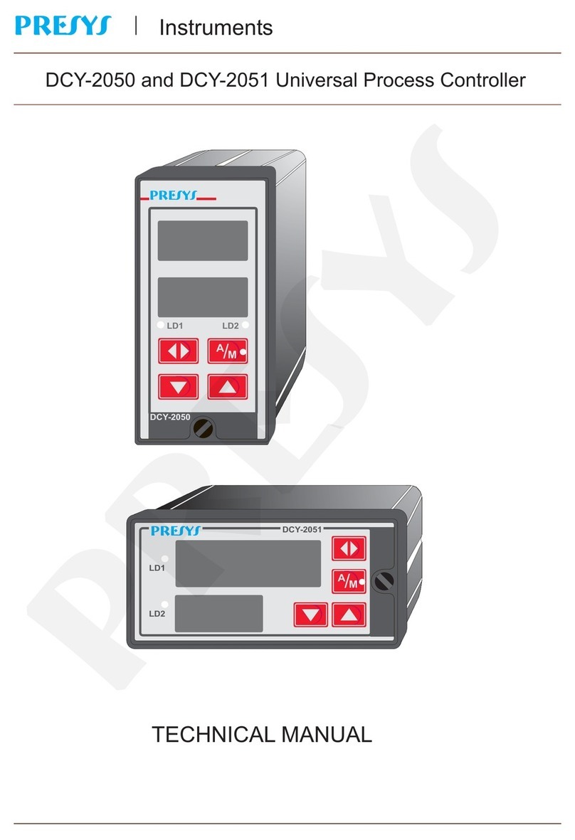
DCY-2057 Pressure Controller
TECHNICAL MANUAL
Instruments
PRESYS
LD1 LD2
PRESYS
DCY-2057
A
M
/
PRESYS

PRESYS | Instruments
DCY - 2057 Pressure Controller
EM0127-00
TABLE OF CONTENTS
Page
1 - Introduction......................................................................................... 1
1.1 - Description...................................................................................... 1
1.2 - Order Code Number........................................................................ 3
1.3 - Technical Specifications.................................................................. 4
2 - Installation........................................................................................... 8
2.1 - Mechanical Installation.................................................................... 8
2.2 - Electrical Installation........................................................................ 8
2.3 - Process Input Signal Connection..................................................... 9
2.3.1 - Thermocouple Connection......................................................... 10
2.3.2 - RTD Connection........................................................................ 10
2.3.3 - Milliampere Input....................................................................... 11
2.3.4 - V or mV Input............................................................................ 13
2.4 - Control and Alarm Output Signal Connection.................................. 13
2.5 - Connection Diagram........................................................................ 16
2.6 - Communication............................................................................... 17
2.7 - Engineering Units............................................................................ 17
3 - Operation............................................................................................. 18
3.1 - Normal Operation............................................................................ 18
3.2 - Configuration................................................................................... 21
3.2.1 - Level 1 - General...................................................................... 24
3.2.2 - Level 2 - Inputs......................................................................... 26
3.2.3 - Level 3 - Outputs...................................................................... 30
3.2.4 - Level 4 - Alarms....................................................................... 32
3.2.5 - Level 5 - Control....................................................................... 34
3.2.6 - Level 6 - Tune.......................................................................... 41
3.2.7 - Level 7 - SetP (Programmable Setpoint)................................. 46
3.2.8 - Level 8 - Calibration................................................................. 49
3.2.9 - Level 9 - RS............................................................................. 49
4 - Maintenance........................................................................................ 50
4.1 - Controller Hardware........................................................................ 50
4.2 - Hardware Configuration................................................................... 51
4.3 - Snubber Use for Relay.................................................................... 52
4.4 - Optional Module Connection........................................................... 53
4.5 - Calibration....................................................................................... 56
4.6 - Hardware Maintenance Instructions................................................ 64
4.7 - List of Components......................................................................... 66
4.8 - List of Recommended Spare Components...................................... 70
PRESYS

PRESYS | Instruments
DCY - 2057 Pressure Controller
Introduction
Page 1
1 - Introduction
1.1 - Description
The PRESYS DCY-2057 Controller is a microprocessor-based instrument
which control and show any process variable found in industrial plants, such as:
pressure, temperature, flow, level etc. It is provided with two types of non-volatile
internal memories (E2PROM and NVRAM) to store configuration and calibration
values. Its high accuracy is warranted by auto-calibration techniques based on high
thermal stability voltage reference.
It can communicate with computers by optional communication module
RS-232 or RS-422/485.
The DCY-2057 Controller was designed according to modularity and flexibility
concepts. Therefore, five plug-in points are provided inside the Controller for the
installation of optional modules. By acquiring just these optional modules, the user is
capable of transforming a Single-Loop Controller, into a Dual-Loop Controller, of
obtaining a wide variety of control output types, such as: by relay, by open collector
voltage, by solid-state relay, voltage (1 - 5V, 0 - 10V), current (4 - 20mA). It can even
be provided with three alarm module types, such as: by relay, by open collector
voltage and by solid-state relay.
It is provided with several control modes: ON-OFF, PID (with all its
combinations), time proportioning, programmable setpoint, cascade and remote
setpoint input.
The DCY-2057 Controller is provided with auto-tune algorithm to compute the
PID parameters for optimizing control capabilities.
It incorporates all standard control characteristics, such as: auto-manual
bumpless transfer, output saturation, remote setpoint and programmable setpoint up
to ten segments, protection against integral saturation, etc.
It is capable of monitoring two inputs. Input 1 is a pressure input, and input 2
can be configured as another pressure input or as an universal standard analogical
input.
Thus, the Controller can accept one or two inputs of gage or absolute pressure
or vacuum. There are versions available for use with air and inert gases or sealed for
fluids compatible with 316L stainless steel. In the version for single pressure input,
the second input accepts the connection of 4-20mA, 1-5VDC, 0-10VDC,
thermocouple and RTD.
The thermocouple and RTD inputs are automatically linearized by means of
tables stored in the EPROM memory. A 24VDC voltage source, isolated and with
short circuit protection, is provided for transmitter power supply.
Except for pressure input, the input type for channel 2 can be selected by the
user and enabled by jumpers and software configuration. All configuration data can
be protected by a password system, and are stored in the non-volatile memory in the
event of a power failure.
PRESYS

PRESYS | Instruments
DCY - 2057 Pressure Controller
Introduction
Page 2
It accepts 90 to 240VAC or 130 to 340VDC (with any polarity) power supply.
The instrument is housed in an extruded aluminum case which makes it highly
immune to electrical noise, electromagnetic interference and resistant to the most
severe and rough industrial use conditions.
DCY-2057
Fig. 1 - DCY - 2057 Controller Front Panel.
On the instrument front panel there are two red displays configurable with the
decimal point for up to four high visibility digits. The upper display can either show the
controlled variable or the mnemonics SP 1, SP 2, OUT 1, OUT 2 corresponding to
the values shown on the lower display. The lower display can show the following
values: channel 1 setpoint, channel 2 setpoint, channel 1 output and channel 2
output. The control outputs 1 and 2 are represented in percentage of full scale
output. The functions of the UP, DOWN and ENTER keys to change the
setpoint/output values are described in section 3.1. The A/M key on the Controller
front panel allows toggling between automatic and manual modes. The green led in
the A/M key indicates, when illuminated, the Controller is in the manual mode and,
when extinguished, the Controller is in the automatic mode. In the Controller
configuration modes both displays show the mnemonics and the parameter values.
The pair of red leds can be used as a visual alarm indication associated to the
outputs of alarms 2, 3 and 4, or can indicate that the measured variable and the
setpoint/output shown on the displays refer to 1 or 2 control loops. We may be
provided with up to three alarm outputs. Each of those alarm outputs may be: by
relay, by open collector or by triac.
PRESYS

PRESYS | Instruments
DCY - 2057 Pressure Controller
Introduction
Page 3
1.2 - Order Code Number
Input 1
Range
Pressure Type
Sensor Type
Input 2
Output 1 (Only for Control)
Output 2 (Control or Alarm)
Output 3 (Only for Alarm)
Output 4 (Only for Alarm)
Power Supply
Communication
Case Protection Grade
1 - 0 - 10"H O (air and inert gases)
2 - 0 - 1psi ( )
3 - 0 - 5psi ( )
4 - 0 - 15psi ( )
5 - 0 - 30psi ( )
6 - 0 - 100psi ( )
7 - 0 - 250psi (sealed)
8 - 0 - 500psi ( )
9 - 0 - 1000psi ( )
1 - Gage
2 - Absolute
3 - Vacuum (0 to 1atm)
1 - For air and inert gases
2 - Sealed for fluids compatible with
316L stainless steel
Same code of Input 1. For single pressure version,
put 0 - 0 - 0 for auxiliary universal input for RTD, TC,
4-20mA, 0-55mVdc, 1-5Vdc and 0-10Vdc.
0 - None
1 - 4 - 20mA
2 - 1 - 5Vdc
3 - 0 - 10Vdc
4 - SPST Relay
5 - Open Collector Voltage
Same code of Output 1
0 - None
1 - SPDT Relay
2 - Open Collector Voltage
Same code of Output 3
1 - 90 to 240Vac or 130 to 340Vdc
2 - 24Vdc
3 - 12Vdc
4 - Others, under consult
0 - None
1 - RS-232
2 - RS-485
3 - RS-422
0 - General usage, protected place
1 - Front aspersion-proof
2 - Weather-proof
2air and inert gases
air and inert gases
air and inert gases or sealed
air and inert gases or sealed
air and inert gases or sealed
sealed
sealed
P.S. COM. CASE
DCY-2057
INPUT 1 INPUT 2 OUTPUT
1 2 3 4
Note 1: The spans and input types, control algorithms, the indication, the use of
relays as alarms and the alarm points are, among others, items which the user may
program through the front keys (if desired, specify this information so that all the
configuration can be made by PRESYS).
Note 2: Other hardware and software features can be available under previous
consult.
PRESYS

PRESYS | Instruments
DCY - 2057 Pressure Controller
Introduction
Page 4
Code Example:
1) DCY - 2057 - 6 - 1 - 1 - 8 - 1 - 2 - 1 - 4 - 1 - 1 - 1 - 0 - 0
This code defines a DCY - 2057 Controller with two pressure inputs, the first in
the 0 to 100 psi range, gage pressure and use with air, the second in the 0 to 500 psi
range, gage pressure and use with fluid. It provides output 1 with 4 to 20mA, output 2
with SPST relay, outputs 3 and 4 with SPDT relay. Power supply in the 90 to 240VAC
ou 130 to 340VDC range, does not use communication and is intended for use in a
sheltered place. The use of such optional modules allows a practical application such
as PID control for channel 1 (output 1) and ON-OFF control for channel 2 (output 2).
Outputs 3 and 4 can be configured as high, low or deviation alarm outputs for
channel 1 or channel 2.
1.3 - Technical Specifications
Inputs:
•One or two pressure inputs for gage, absolute or vacuum pressure. Ranges
from 0 to 250 mmH2O (0 to 10”H2O), 0 to 1 psi, 0 to 5 psi, 0 to 15 psi, 0 to 30
psi, 0 to 100 psi, 0 to 250 psi, 0 to 500 psi and 0 to 1000 psi for gage pressure.
Same ranges beginning from 15 psi for absolute pressure. VACuum ranges
from 0 to 1 atm.
•Ranges up to 15 psi used with air and inert gases. From 15 psi up to 250 psi,
sensors are available for air or fluids. Above 250 psi they are sealed for use
with fluids compatible with 316L stainless steel. Note: the sersor for fluids also
accepts air / gases, but the opposite is not allowed.
•Auxiliar universal input, for the single pressure input version, configurable for
thermocouple (J, K, T, E, R, S, under ITS - 90), RTD Pt - 100 under DIN 43760,
4 to 20mA, 0 to 55mVDC, 1 to 5VDC, 0 to 10VDC. Input impedance of 250Ωfor
mA, 10MΩfor 5VDC and 2MΩabove 5VDC.
•Table 1 shows the pressure range limits, thermocouple and RTD temperature
range limits and the resolution for the linear input sensors.
PRESYS

PRESYS | Instruments
DCY - 2057 Pressure Controller
Introduction
Page 5
Input sensor Span
Sensor lower
limit
psi
higher
limit
psi
250 mmH2O 0 0.355
1 psi 0 1.000
Pressure 5 psi 0 5.000
15 psi 0 15.00
30 psi 0 30.00
100 psi 0 100.0
250 psi 0 250.0
500 psi 0 500.0
1000 psi 0 1000
Thermocouple lower
limit
°F
higher
limit
°F
lower
limit
°C
higher
limit
°C
Type J -184.0 1886.0 -120.0 1030.0
Type K -346 2498 -210 1370
Type T -418 752 -250 400
Type E -148.0 1436.0 -100.0 780.0
Type R -58 3200 -50 1760
Type S -58 3200 -50 1760
RTD Pt-100 2- or 3-wire
-346.0
1256.0
-210.0
680.0*
Linear
Span
Resolution
Voltage 0 to 55mV
6μV
0 to 5V
500μV
0 to 10V
1mV
Current 0 to 20mA
2μA
(*) including wire resistance
Table 1 - Input Sensor Measuring Span
Control functions:
* ON-OFF Control. * Cascade Control.
* PID Control. * Remote setpoint input
* PID Control with AUTO-TUNE. * Programmable setpoint
* Ratio Control.
PRESYS

PRESYS | Instruments
DCY - 2057 Pressure Controller
Introduction
Page 6
Control outputs:
. Analog output 4 to 20mAdc, 1 to 5VDC, 0 to 10VDC, use of optional cards with
plug-in fitting foreseen for up to two 300 VAC modules galvanically isolated from
inputs and power supply. Maximum load of 750Ω.
. SPST relay output with 3A capacity at 220VAC.
. Open collector voltage output (24VDC, 20mA maximum with isolation).
. Solid-state relay output (2A 250VAC with isolation).
Alarm outputs:
. SPST relay output with 3A capacity at 220VAC.
. SPDT output relay with 3A capacity at 220VAC.
. Open collector voltage output (24VDC, 20mA maximum with isolation).
. Solid-state relay output (2A 250VAC with isolation).
Serial communication:
RS-232 or RS-422/485 with isolation at 50VDC, as an optional module with
plug-in fitting independent from outputs.
Engineering Units:
psi, atm, inH2O, kgf/cm2, mH2O, inHg, mmHg, cmHg, bar, mbar, kPa and
mmH2O.
Indication:
Two red display sets with four digits which can be jointly configured with the
decimal point.
Configuration:
By front panel pushbuttons and internal jumpers.
Scanning time:
Standard 130 ms, for input indications within the -999 to 9999 span. Display
updating at each 0.5 second.
Accuracy:
±1 % of full scale for 0 to 250 mmH2O range.
±0.1% of full scale for other pressure ranges.
±0.1% of full scale for TC, RTD inputs, mA, mV, VDC.
±0.5% of full scale for analog control output.
Linearization:
±0.1% for RTD and ±0.2% for TC.
PRESYS

PRESYS | Instruments
DCY - 2057 Pressure Controller
Introduction
Page 7
Square root extraction:
±0.5% of readings, for input above 10% of span. 0 to 5% of programmable Cut-
off.
Cold junction compensation:
±2.0°C in the range from 0 to 50°C of ambient temperature.
2-Wire transmitter power supply:
24VDC voltage and 50mA maximum, isolated from outputs, with short-circuit
protection.
Stability at ambient temperature:
±0.005% per °C of span referred to an ambient temperature of 25°C.
Power supply:
Universal 90 to 240VAC or 130 to 340VDC (any polarity), 10W nominal;
24VDC, 12VDC and other values are optional.
Operating ambient:
0 to 50°C temperature and 90% maximum relative humidity.
Dimensions:
1/4 DIN (96 X 96mm) and 162mm depth.
92 X 92 mm panel cutout.
Pneumatic / hydraulic connection:
Junction for 1/4” plastic tube for using with air or 1/4” NPTF for using with other
fluids.
Weight:
0.5kg nominal.
Warranty:
One year.
PRESYS

PRESYS | Instruments
DCY - 2057 Pressure Controller
Installation
Page 8
2 - Installation
2.1 - Mechanical Installation
The DCY - 2057 Controller front panel has 1/4 DIN size (96 X 96 mm).
It is fixed by the rails which press it against the back side of the panel.
After preparing a 92 X 92 mm cut in the panel, remove the rails from the
Controller and slide its rear through the cut until its front reaches the panel. Place the
rails again in the Controller from the back of the panel and tighten the screws as
shown in figure 2.
Fig. 2 - Dimensional drawing, panel cutout and side view
2.2 - Electrical Installation
DMY-2017 Controller may be powered by voltage between 90 and 240VAC or
130 to 340VDC, any polarity. Remember that the internal circuit is powered whenever
the instrument is connected to the external power supply.
Input and output signals must be connected to the instrument only when it is
turned off.
Figure 3 shows the instrument rear terminals for connection of power supply,
ground, communication, process input and output signals.
Signal wiring must be kept far away from power wires.
Due to its metal case the instrument ground should be connected to earth
ground. Never connect the ground to neutral terminal.
PRESYS

PRESYS | Instruments
DCY - 2057 Pressure Controller
Installation
Page 9
Fig. 3 - DCY-2057 Controller Terminals
2.3 - Process Input Signal Connections
Pressure inputs 1and 2 (optional), shown in figure 3, require pneumatic /
hydraulic connection with junction for 1/4” plastic tube for use with air or 1/4” NPTF
for use with other fluids.
The single pressure version of the Controller accepts connection to
thermocouples, 2 or 3-wire RTDs, mA, mV or V. In order to know the input sensor
types and spans refer to table 1, section 1.3 on Technical Specifications.
A certain type of input sensor is enabled by means of internal jumpers
(refer to section 4.2 on Hardware Configuration) and by the proper sensor
selection in configuration mode (refer to section 3.2 on Configuration).
Therefore, the connections explained below shall only become effective if the
instrument hardware and software are correctly configured.
The connection of a certain type of sensor in input 1 does not restrict the
simultaneous use of other sensor, of the same type or different, in input 2.
In order to avoid noise in the wiring, use twisted pair cable and cross sensor
connection wire inside a metallic tube or use shielded cable. Make sure to connect
only one shield wire end either to board terminal or to sensor ground, as shown in the
next items.
WARNING: GROUNDING TWO SHIELD WIRE ENDS MAY CAUSE NOISE IN THE
CONTROLLER.
PRESYS

PRESYS | Instruments
DCY - 2057 Pressure Controller
Installation
Page 10
2.3.1 - Thermocouple Connection
Connect the thermocouple to terminals 5(+) and 6(-) of input 2 as shown in
figure 4.
Use appropriate compensating cables with the same material of the
thermocouple in order to connect it to the instrument. Check if the thermocouple
polarity is equal to those of the terminals.
Fig. 4 - Thermocouple Connection
2.3.2 - RTD Connection
A RTD accepts a 2-, 3-, or 4-wire connection. All connection types are shown
in figure 5.
In case of a 2-wire RTD, connect the RTD between terminals 4 and 6 as
illustrated in figure 5.
For a 3-wire RTD, connect the RTD in the same way as for the previously
described 2-wire connection, except that a third wire for RTD compensation should
be connected to terminal 5, see figure 5.
A 4-wire RTD should be connected to the Controller in the same manner as a
3-wire connection, except that the fourth RTD wire is disregarded and left
disconnected, see figure 5.
The use of a 3-wire RTD provides a higher accuracy than a 2-wire connection.
The RTD wiring should be of the same material, length and gauge to ensure
proper resistance compensation on all terminal connections. The maximum
connecting wire resistance is 10 Ωper wire. The minimum wire gauge should be 18
AWG for distances of up to 50 meters and 16 AWG for distances above 50 m.
PRESYS

PRESYS | Instruments
DCY - 2057 Pressure Controller
Installation
Page 11
Fig. 5 - RTD Connection
2.3.3 - Milliampere Input
A standard 4 to 20mA current source can be applied between terminals 4(+)
and 6(-) of input 2; this current signal can originate from an externally powered
Transmitter. In case that the internal 24V voltage source of the Controller is used to
power a 2-wire Transmitter, current is received only on terminal 4(+). Figure 6
illustrates those two connection possibilities.
PRESYS

PRESYS | Instruments
DCY - 2057 Pressure Controller
Installation
Page 12
Fig. 6 - Current source Connection
PRESYS

PRESYS | Instruments
DCY - 2057 Pressure Controller
Installation
Page 13
2.3.4 - mV or V Input
Either a 0 to 55mVDC or a 0 to 5VDC voltage must be applied between
terminals 5(+) and 6(-) of input 2. A 0 to 10VDC voltage must be applied between
terminals 4(+) and 6(-) of input 2. These connections are illustrated in figure 7.
Fig. 7 - Voltage Source Connection
2.4 - Control and Alarm Output Signal Connection
In the most complete version the Controller can be provided with up to four
output signals: output 1, output 2, output 3 and output 4. Output 1 can only be used
as a control output. Output 2 can be used as control or alarm output, depending on
the Controller software configuration established by the user. Outputs 3 and 4 can be
used as alarm outputs. A maximum of three alarm outputs can be provided.
PRESYS

PRESYS | Instruments
DCY - 2057 Pressure Controller
Installation
Page 14
In case of outputs 1 and 2 we can have six types of different outputs between
the current I/O terminals: current (4 to 20mA), voltage (0 to 5VDC), voltage (0 to
10VDC), SPST relay, open collector voltage and solid state relay.
For outputs 3 and 4 there are three types of different outputs: SPDT relay,
open collector voltage and solid-state relay. Figure 8 illustrates the control outputs
and figure 9 the alarm outputs of the Controller.
Note that the I/O terminals will only show output signals if the corresponding
optional module is installed and the output is correctly configured. Refer to sections
3.2 on Configuration and 4.4 on Optional Module Connection for further details on
installation and configuration of optional modules.
(1) Designates first control loop
(2) Designates second control loop
Fig. 8 - Control Output Connections
PRESYS

PRESYS | Instruments
DCY - 2057 Pressure Controller
Installation
Page 15
15
17
20
16
18
21
19
22
OUTPUT 2
OUTPUT 3
OUTPUT 4
FUNCTION INTERNAL DEVICE TERMINALS
Alarm
Alarm
Alarm
SCR
SCR
SCR
SPDT
SPST
SPDT
NC
NC
C
C
C
NO
NO*
+24V
+24V
+24V
Logic
Logic
Logic
*
NC
*
*
*
-
(*) Relay contact states shown are valid for SAFE option selected (see section 3.2 on Configuration), Controller
powered on and non-alarm condition. Position of the contacts are changed in alarm condition (with SAFE option
selected) or when the instrument is turned off.
Fig. 9 - Alarm Output Connections
PRESYS

PRESYS | Instruments
DCY - 2057 Pressure Controller
Installation
Page 16
2.5 - Connection Diagram
PRESYS

PRESYS | Instruments
DCY - 2057 Pressure Controller
Installation
Page 17
2.6 - Communication
DCY-2057 Controller communicates with computers through RS-232 or
RS-422/485 and with use of a MODBUS protocol communication software, when the
optional communication modules are installed and the communication parameters
are configured.
Specific information on communication and signal connection are described in
the communication manual.
2.7 - Engineering Units
A label with several Engineering Units is supplied with each Controller. Select
the one corresponding to the variable shown on the display and stick it to the front
panel of the Controller.
PRESYS

PRESYS | Instruments
DCY - 2057 Pressure Controller
Operation
Page 18
3 - Operation
3.1 - Normal operation
The DCY-2057 Controller has two modes of operation: normal mode and
configuration mode.
In normal operation mode we can further have the automatic operation mode
and the manual operation mode.
In the automatic operation mode (closed loop system) the Controller receive
the input signals, compare them with the setpoints and automatically generate
through control algorithms the output signals which adjust the input signals to the
setpoints.
In the manual operation mode (open loop system) the user himself establishes
the values in output percentage to control the measured variables.
The selection between the automatic and manual modes is made through the
automatic/manual (A/M) key on the Controller front panel. When in the manual mode
the green LED, indicating the manual state, is on.
The Controller normal mode, in which it operates most of the time, will be
named zero level. In this level the upper display can show: denomination of setpoint
1 (SP 1), denomination of output 1 (OUT1), denomination of setpoint 2 (SP 2),
denomination of output 2 (OUT2), value of input 1 (IN 1) and value of input 2 (IN 2).
The lower display can show: the value of setpoint 1 (V_SP 1), the value of output 1
(V_OUT 1), the value of setpoint 2 (V_SP2) and the value of output 2 (V_OUT 2).
Whenever the Controller is powered on, it starts a display indication of the last
selection shown, before being disconnected. In order to switch to other options, the
UP, DOWN and ENTER keys should be used, as illustrated in figure 10.
Figure 10, below, illustrates all the display presentation possibilities at the
operation level.
PRESYS
Table of contents
Other Presys Controllers manuals
