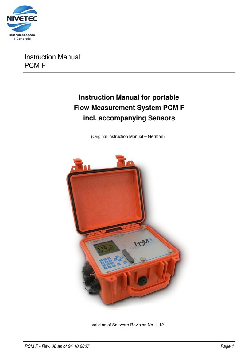
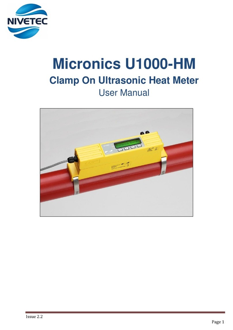
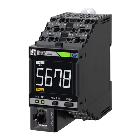
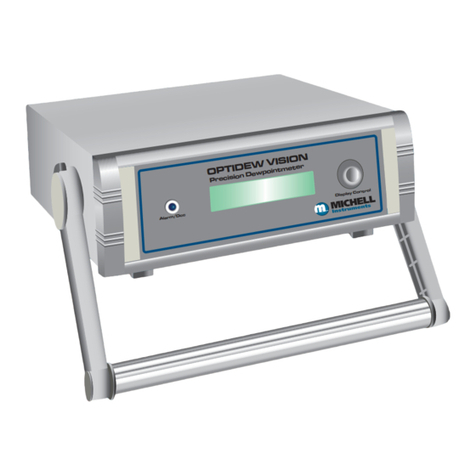
Nivetec AquaSensors AV88 User manual

Thermo Scientific AquaSensors™
AV88 Universal Analyzer
and Controller
User Guide

ROSS and the COIL trade dress are trademarks of Thermo Fisher Scientific Inc. U.S. patent 6,793,787.
AQUAfast, Cahn, ionplus, KNIpHE, No Cal, ORION, perpHect, PerpHecT, PerpHecTion, pHISA, pHuture, Pure Water, Sage, Sensing the Future, SensorLink,
ROSS, ROSS Ultra, Sure-Flow, Titrator PLUS and TURBO2 are registered trademarks of Thermo Fisher.
1-888-pHAX-ION, A+, All in One, Aplus, AQUAsnap, AssuredAccuracy, AUTO-BAR, AUTO-CAL, AUTO DISPENSER, Auto-ID, AUTO-LOG, AUTO-READ,
AUTO-STIR, Auto-Test, BOD AutoEZ, Cable-Free, CERTI-CAL, CISA, DataCOLLECT, DataPLUS, digital LogR, DirectCal, DuraProbe, Environmental Product
Authority, Extra Easy/Extra Value, FAST QC, GAP, GLPcal, GLPcheck, GLPdoc, ISEasy, KAP, LabConnect, LogR, Low Maintenance Triode, Minimum Stir
Requirement, MSR, NISS, One-Touch, One-Touch Calibration, One-Touch Measurement, Optimum Results, Orion Star, Pentrode, pHuture MMS, pHuture
Pentrode, pHuture Quatrode, pHuture Triode, Quatrode, QuiKcheK, rf link, ROSS Resolution, SAOB, SMART AVERAGING, Smart CheK, SMART STABILITY,
Stacked, Star Navigator 21, Stat Face, The Enhanced Lab, ThermaSense, Triode, TRIUMpH, Unbreakable pH, Universal Access are trademarks of
Thermo Fisher.
.
© 2009 Thermo Fisher Scientific Inc. All rights reserved. All trademarks are the property of Thermo Fisher Scientific Inc. and its subsidiaries.
The specifications, descriptions, drawings, ordering information and part numbers within this document are subject to change without notice.
This publication supersedes all previous publications on this subject.

Thermo Scientific AquaSensors™AV88 Universal Analyzer User Guide 1
Preface
This instruction manual serves to explain the use of the Thermo Scientific AquaSensors AV88
Universal Analyzer and is written to cover as many applications as possible. Please do not
hesitate to contact Thermo Fisher Scientific or an authorized representative with questions or
concerns.
The information presented in this instruction manual is subject to change without notice as
improvements are made, and does not represent any commitment whatsoever on the part of
Thermo Fisher Scientific.
Thermo Fisher Scientific cannot accept any responsibility for damage or malfunction of the
product due to improper use.
Contact Information
To contact Thermo Scientific AquaSensors Technical Support:
Within the United States call 1.800.225.1480 or fax 978-232-6015.
Outside the United States call 978.232.6000 or fax 978.232.6031.
In Europe, the Middle East and Africa, contact your local authorized dealer.
Visit us on the web at www.thermo.com/processwater

Thermo Scientific AquaSensors™AV88 Universal Analyzer User Guide 2
Safety Information
The Thermo Scientific AquaSensors AV88 Universal Analyser shallbe
installed and operated only in the manner specified. Only a skilled,
trained or authorized person should carry out installation, setup and
operation ofthe sensor system.
Before using the display, make sure that the sensor cable is
connected as specified. Failure to do so may result in permanent
damage to the system ofits components.
Protection against electric shock will be achieved only by observance
of the corresponding installation rules.

Thermo Scientific AquaSensors™AV88 Universal Analyzer User Guide 3
TABLE OF CONTENTS
1. INTRODUCTION ........................................................................................................................................................4
1.1. GENERAL INFORMATION................................................................................................................4
1.2. INTENDED USE...............................................................................................................................5
2. PRODUCT DESCRIPTION........................................................................................................................................6
2.1. SYSTEM OVERVIEW.......................................................................................................................6
2.2. MOUNTING ...................................................................................................................................6
2.3. POWER, RELAY AND CURRENT LOOP WIRING .............................................................................. 10
2.4. PERSONALITY MODULE INSERTION AND REMOVAL ......................................................................11
2.5. SENSOR PARAMETER WIRING ...................................................................................................... 12
2.6. HOST COMMUNICATIONS WIRING................................................................................................13
2.7. MEASURE SCREEN OVERVIEW .....................................................................................................13
3. MENU STRUCTURE AND NAVIGATION..............................................................................................................15
4. CALIBRATE MENUS...............................................................................................................................................19
4.1. 2-POINT BUFFER CALIBRATION (SENSOR TYPE: PH).................................................................... 21
4.2. ABORTED CALIBRATION (SENSOR TYPE: ALL)............................................................................24
4.3. 1-POINT SAMPLE CALIBRATION (SENSOR TYPE: ALL) ................................................................25
4.4. ZERO CALIBRATE MENU (SENSOR TYPE: CONDUCTIVITY, DO, TURBIDITY) ................................ 28
4.5. AIR CALIBRATION (SENSOR TYPE: D.O. )................................................................................... 30
4.6. TEMPERATURE 1-POINT SAMPLE CALIBRATION............................................................................ 32
5. CONFIGURE MENU.................................................................................................................................................35
5.1. MAIN CONFIGURE MENUS ...........................................................................................................36
5.2. NAVIGATING SENSOR FILTER CONFIGURATION ............................................................................37
5.3. NAVIGATING THE USER-ENTERED CONCENTRATION TABLE SCREENS........................................... 40
6. HOST COMMUNICATIONS.....................................................................................................................................46
7. ANALOG OUTPUT MENUS....................................................................................................................................46
7.1. ASSIGNING 4 MA AND 20 MA PARAMETER VALUES...................................................................... 47
7.2. CALIBRATING OUTPUT CURRENT................................................................................................. 48
8. PID CONTROLLER..................................................................................................................................................50
9. RELAY MENUS........................................................................................................................................................52
10. HELP MENU.............................................................................................................................................................54
11. LIMITED WARRANTY.............................................................................................................................................55
12. TERMS AND CONDITIONS....................................................................................................................................56
TABLE OF TABLES
Table 1: A typical concentration table with four points........................................................................................40
Table 2: Record the table values here before entering them............................................................................... 41
Table 3: Summary ofkey actions. ..................................................................................................................44
Table 4: The default concentration table..........................................................................................................45

Thermo Scientific AquaSensors™AV88 Universal Analyzer User Guide 4
1. INTRODUCTION
1.1. General Information
Thank you for purchasing the Thermo Scientific AquaSensors AV88 Universal Analyzer.
The productis designed for continuous use in industrialprocess applications and complies with safety
regulations currently in force. Improper use could lead to hazards for the user or a third-party, and/or adverse
effects to the plant or other equipment.
Thermo Fisher Scientific does not accept any liability for damage that may arise if information in this
manual is not followed. Therefore, the operating instructions and specifications must be read and
understood by all persons involved in installation and operation of this equipment.
This manualidentifies safety instructions and additional information by means ofthe following symbols:
This symbol draws attention to safety instructions and warnings of potential danger,
which ifneglected,could result in injury to persons and/or damage to property.
This symbol identifies additional information and instructions, which if neglected, could
lead to inefficient operation and possible loss of production.
Itis recommended that this manual be made accessible to everyone who may need it as a reference.
Please contactThermo Fisher Scientific or an authorized representative with any questions.

Thermo Scientific AquaSensors™AV88 Universal Analyzer User Guide 5
1.2. Intended use
The Thermo Scientific AquaSensors AV88 Universal Analyzer is used to monitor, configure, calibrate and
diagnose all AnalogPlus sensor parameters. AnalogPlus sensors must be ordered specifically for the AV88.
Thermo Fisher Scientific also carries AnalogPlus replacement sensors that connect to competitors’ analyzers.
Data is reported through two scalable 4-20 milliamp current outputs or through one of several digital protocols.
Options include outputs configured for PID and up to 2 relays.
Any other use,or use not mentioned here, that is incompatible with the technical specifications is deemed
inappropriate. The operator is solely responsible for anydamage arising from such use.
Other prerequisites for appropriate use include:
•Observing the instructions, notes and requirements setout in this instruction manual.
•Observing all local safety regulations.
•Observing all warnings and cautions in the documentation regarding all products used in this
measurementsystem, including the sensor, mounting hardware, AV88 electronics and cabling.
•Observing the prescribed environmentaland operational conditions.
•Observing chemical compatibility with all wetted materials.
1.3. Safety Instructions
The AV88 Universal Analyzer should be installed and operated only by personnel
familiar with the sensor and qualified for such work.
A defective AV88 should be returned to Thermo Fisher Scientific for repair or
replacement. Contact Thermo Fisher Scientific to obtain a Return Material
Authorization (RMA) number.
No modifications to the AV88s are allowed. The manufacturer/supplier accepts no
responsibility for damage caused by unauthorized modifications. The risk is borne
entirely by the user.
1.4. Removal from Service / Correct Disposal of the AV88 Universal Analyzer
Removal from Service
•Disconnect the cable wiring from the analyzer terminal block.
•Remove the AV88 from the mounting hardware.
Correct Disposalof Unit
•When the AV88 is taken out of service, observe the local environmental regulations for correct
disposal.

Thermo Scientific AquaSensors™AV88 Universal Analyzer User Guide 6
2. PRODUCT DESCRIPTION
2.1. System Overview
The AV88 is a universal analyzer for use with allAV88 enabled AnalogPlus sensors. The enclosure has -DIN
dimensions for easy mounting and is rated NEMA 4X for outdoor use. Ituses a liquid crystal display (LCD) with
a high contrast backlight for best readability and is
powered with 24 volts DC.
The AV88 is quickly configured for a specific sensor
type with a small plug-in personality module adjacent to
the sensor terminalblocks. This module provides
wiring information about specific sensor connections
and provides the appropriate calibration, configuration
and diagnostic menus. When there is no plug-in
personality module configured inside the AV88, the
measure screen will show dashed lines.
The AV88 has two standard 4-20 current loops.
Options include two alarm/control relays and network
communications to a host computer.
Host communication options include, Modbus,
DeviceNet,RS-232 ASCII, Profibus and others.
There are sevenkeys for menu navigation. The MENU key provides options for calibration, configuration,
communications, outputs and relays. The ESC key is used to return to the measure screen.
2.2. Mounting
The AV88 can be mounted on a wallor panel mounted in -DIN or -DIN forms. A gasket is built into the
display for a NEMA 4Xseal. Mounting instructions must be followed to maintain seals. The AV88 can be pipe
mounted and panelmounted with optional mounting hardware.
2.2.1. Conduit Box Wall Mount
The AV88 conduit box is mounted to a wallor plate with #8 or M4 screws through the mounting holes as
shown. There are seven Pg11 and Pg16 knockouts in the conduitbox. Two cord grips are supplied and it is
recommended thatthey be used in the conduit holes onthe bottomside of the box to prevent rain or moisture
from settling at the conduit interface. It is also possible to mount the box using interior breakouts. Four plastic
caps are provided to seal the interior mounting screws. Nema 4X ratings will be maintained only when the #8
mounting screws are used in the holes outside the conduitbox gasket.

Thermo Scientific AquaSensors™AV88 Universal Analyzer User Guide 7
AV88 conduit box is mounted to a
wall or plate with #8 or M4 screws
through the mounting holes as
shown.
Seven Pg11/16 Conduitbreakouts
are available for cord grips or conduit
hardware.

Thermo Scientific AquaSensors™AV88 Universal Analyzer User Guide 8
2.2.2. -DIN Panel Mount
A -DIN panel mount bezel and gasket can be ordered to fit the AV88 as shown. The AV88 display is
tightened down to the bezel using the four captured screws in the AV88.The bezel is then mounted to a -DIN
square opening with the hardware shown in the figure below.
AV88

Thermo Scientific AquaSensors™AV88 Universal Analyzer User Guide 9
2.2.3. -DIN Panel Mount
The AV88 Display can be mounted directly to a -DIN panel opening using the captive mounting screws in the
AV88 and the -DIN supports as illustrated in the figure below. A -DIN bezel gasket can be provided to
ensure a NEMA 4Xseal on the panel.
AV88

Thermo Scientific AquaSensors™AV88 Universal Analyzer User Guide 10
2.3. Power, Relay and Current Loop Wiring
The AV88 Display comes with two terminal blocks. The 10-pin block on the leftis used to hook up two current
loops and two relays (if installed). The 12-pin terminalblock on the rightis used to hook up 24-volt power, host
communications (if installed) and one of many analyticalsensors. There is a sensor personality module for
each sensor type thatis plugged in and fastened downas shown iffigure 2.1A.
Sensor personality modules show which sensor the AV88 is configured for and provide wiring information.
Figure 2.1A: AV88 wiring when configured for Differential pH
Two Form C
Relays
24 VDC Power
(Digital Comms on pins 3
& 4 when option installed)
Two Current
Loops
Differential pH Sensor
Wiring
Lock nut to retain pH
personality module Push/Pull rod to
remove pH personality
module
Personality module
label shows pH
parameter, functions
and wire colors.

Thermo Scientific AquaSensors™AV88 Universal Analyzer User Guide 11
2.4. Personality Module Insertion and Removal
The AV88 can be configured to work with any AnalogPlus sensor parameter by installing the desired
personality module.
Removal
To remove a personality module,disconnectthe sensor cable from the screw terminals, remove the acorn nut
from the center ofthe box and then pull on the push/pull rod as shown in Figure 2.1B. Be sure to keep the
acorn nut in a safe place so that a new module can be properly secured.
Insertion
Hold the personality module by the push/pull rod.
Insert the guidepost through the alignmenthole.
Gently insert the module. Do not force the
connector pins in place.
When the personality module is seated,secure it
by installing the #4-40 Acorn Nut.
The fullfamily of parameter specific personality modules and associated wiring information is shown in Figure
2.1C.
Fi
g
ure 2.1B: AV88 with personalit
y
module removed
Push/Pull Rod
#4-40 Acorn Nut
to secure module
pH Personality Module

Thermo Scientific AquaSensors™AV88 Universal Analyzer User Guide 12
2.5. Sensor Parameter Wiring
The AV88 can be configured to work with any AnalogPlus sensor by installing the appropriate personality
module. Each module clearly shows how to wire the sensor with terminalnumbers, wire colors and sensor
functions.
Currentparameters include: pH,ORP, Contacting Conductivity, Resistivity,Dissolved Oxygen, Dissolved
Ozone, Toroidal Conductivity and Turbidity.
Figure 2.1C: AV88 personality module family

Thermo Scientific AquaSensors™AV88 Universal Analyzer User Guide 13
2.6. Host Communications Wiring
The AV88 can be ordered with or without digitalcommunications to a hostcomputer. Labeling for host
communications on screw terminals 3 and 4 indicates the type of communications provided.
When no host communications option is
installed the label will show “NC” by each
terminal.
2.7. Measure Screen Overview
The AV88 user interface is shown in Figure 2.2. It consists of an LCD module that contains two lines of16
alphanumeric characters and seven keys to navigate the menu. The contrast ofthe LCD module can be
adjusted by simultaneously pressing the escape and up-arrow keys (for more contrast) or the escape and
down-arrow keys (for less contrast).
A pressedkey is identified by a gray background, e.g., .
DeviceNet Modbus RS-232
Terminal 3 CAN_H Comms(-) Tx
Terminal 4 CAN_L Comms(+) Rx
991.3 S/cm AB
30.8 °C
MENU ESC
ENTER
Figure 2.2: The elements of the
AV88
user
interface.
ESC
Figure 2.1D: AV88 Host Communications Wiring
Digital Communications - Terminals 3 and 4.

Thermo Scientific AquaSensors™AV88 Universal Analyzer User Guide 14
When a sensor module of the same type is replaced inthe AV88, currentoutput, PID and relay settings are
maintained. If a sensor module ofa new type is installed, these settings are automatically set to default
conditions appropriate to the new parameter.
The measurescreen is the same for all parameters. Itdisplays the sensor value on the top line and the
temperature on the bottomline.The AB indicators on the far right side of the top line indicate the state of the
relays (whenthis option is installed). Anuppercase letter indicates thatthe corresponding relay is energized.
An underscore indicates thatthe corresponding relay is de-energized. The example in Figure 2.3 illustrates the
display of a conductivity measurementat Station Address 1 with relays A and B energized.
When the Sensor Module is absent, the condition will be indicated by dashes on the measure screen as shown
in Figure 2.4.
Figure 2.3: The measure screen. It shows the
sensor value, sensor units, temperature value,
and temperature units.
991.3 S/cm AB
30.8 °C
MENU ESC
ENTER
---- -- __
---- --
MENU ESC
ENTER
Figure 2.4: The initialmeasure screen when the
Sensor Module is absent.

Thermo Scientific AquaSensors™AV88 Universal Analyzer User Guide 15
3. MENU STRUCTURE AND NAVIGATION
Menus are accessed by pressing the MENU key.
The menu structure is navigated using ENTER, UP/DOWN arrows, and ESC keys.
Use the UP/DOWN arrow keys to scroll through the list of Menu options.
Use the ENTER key to select an option.
Use the ESC key to move up in the structure.
The end of the listof menu options is always the EXIT function. Pressing ENTER on the EXIT screen will bring
up the MEASUREscreen.
The () symbol is used to indicate that the user is in the menu structure. At the leaf of each branch of the menu
structure, the user is able to enter a value or make a choice. The value to be entered or the choice to be made
will be surrounded by parentheses (()). The name of the value being entered or choice being made will appear
on the upper line of the screen and be appended with a question mark (?) to indicate that the user is to provide
input.
The right arrow symbol () on the screen indicates that downward navigation through the menu structure is
possible. The left arrow symbol () on the screen indicates that upward navigation through the menu structure is
possible.
The items in the calibrate and configure menus dependon the type of personality module that is installed in the
AV88.
Main menu options are listed as follows:
Main Menu Item Function
Calibration Sensor calibration choices are automatically available for installed personality
module
Configuration Configuration choices are automatically available for theinstalled personality
module
Analog Output 1 Set4 mA and 20 mA values. Calibrate and test the currentoutput with a meter.
Analog Output 2 Set4 mA and 20 mA values. Calibrate and test the currentoutput with a meter.
PID Controller (option) Setup PID controlfunctions for analog outputs. Available with pH or conductivity
only.
Relay A (option) Setwash, alarm, or control functions. (Optional)
Relay B (option) Setwash, alarm, or control functions. (Optional)
Help Indicates AV88 firmware version
Exit Returns to the measure screen

Thermo Scientific AquaSensors™AV88 Universal Analyzer User Guide 16
MAIN MENU NAVIGATION
Enter the Main Menu by pressing the MENU key.
Scrollthe listing with the UP/DOWN arrow keys.
To select an option, press the ENTER key.
The AV88 remembers thatlast menu option used and will return to that menu option when re-entering the main
menu from the measure screen. The listorder is always the same so ifpressing MENU displays current output
and the desired operation is calibration; the UP arrow will be used to move to the Calibrate menu.
Main Menu
Analog Output 1
MENU
ESC
ENTER
Main Menu
Configure
MENU
ESC
ENTER
Main Menu
Calibrate
MENU
ESC
ENTER
Select CALIBRATE with the ENTER key
To calibrate the main parameter or temperature.
NOTE: Calibrate menus will be sensor specific.
Press the DOWN ARROW for next selection.
Select CONFIGURE with the ENTER key
To display or change filters, units of measure,
constants, tables and buffer standards
NOTE: Configure menus will be sensor specific.
Press the DOWN ARROW for next selection.
Select ANALOG OUTPUT 1with the ENTER key
To set up 4 to 20 mA Analog Output for
sensor, temperature or PID (if Installed).
Press the DOWN ARROW for next selection.

Thermo Scientific AquaSensors™AV88 Universal Analyzer User Guide 17
Main Menu
Analog Output 2
MENU ESC
ENTER
Main Menu
Relay A
MENU ESC
ENTER
Select ANALOG OUTPUT 2with the ENTER key
To set up 4 to 20 mA Analog Output for
sensor, temperature or PID (if installed).
Press the DOWN ARROW for next selection.
Select RELAY A with the ENTER key
To set up Relay A for Alarm, Control or
Wash functions (if installed).
Press the DOWN ARROW for next selection.
Main Menu
Relay B
MENU ESC
ENTER
Select RELAY B with the ENTER key
To set up Relay B for Alarm, Control or
Wash functions (if installed).
Press the DOWN ARROW for next selection.
Main Menu
PID Controller
MENU ESC
ENTER
Select PID CONTROLLER with the ENTER key
To set up ISA or Velocity Algorithm, Full-
Scale, Zero-Scale, Setpoint, Proportion Gain,
Integral Gain, Derivative Gain, Transit time,
manual reset and manual mode.
(Can be used with pH or Conductivity).
Press the DOWN ARROW for next selection.

Thermo Scientific AquaSensors™AV88 Universal Analyzer User Guide 18
991.3 S/cm AB
30.8 °C
MENU ESC
ENTER
Measure Screen
Note: The relay activity indicators “AB”
show that both Relay A and Relay B are
energized.
Main Menu
Exit
MENU ESC
ENTER
Select EXIT with the ENTER key
Return to the measure screen.
Press an UP ARROW to review the menu.
Press ESC for Measure (alternate method).
Main Menu
Help
MENU ESC
ENTER
Select HELP with the ENTER key
To read the AV88 firmware version.
Press the DOWN ARROW for next selection.
Table of contents
Other Nivetec Measuring Instrument manuals
Popular Measuring Instrument manuals by other brands

Emerson
Emerson Rosemount Clarity II T56 quick start guide

ENDEAVOUR
ENDEAVOUR ET2704 manual
Pixsys
Pixsys STR560 user manual

Omega
Omega RD-MV100 Series user guide

PCB Piezotronics
PCB Piezotronics ICP HT352A25 Installation and operating manual
Siemens
Siemens SIRIUS 3SE670 BA Series Original operating instructions

GREISINGER
GREISINGER GTF 103-Ex Series operating manual
Hanna Instruments
Hanna Instruments HI749 instruction manual
Cannon
Cannon CAV-2100 instruction & operation manual

Kobold
Kobold MIK Series operating instructions
Tenma
Tenma Smart Tweezer ST-5S-BT2 manual
Magnetrol
Magnetrol Tuffy 039-6000-100 Installation and operating manual
