Thank you for choosing a NIVELCO instrument.
We are sure that you will be satisfied throughout its use.
APPLICATION
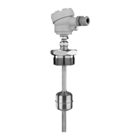
The NIVOPOINT MR series of magnetic float level switches are applicable for point level
switching (high or low) or for alarm (overfill, empty) in liquids.
In case of liquids containing metal particles protect the device by using a magnetic filter.
2. TECHNICAL DATA
Model MR _ _ _ MR _ _ _ Ex
Probe length 0,25...3 m
Material of wetted parts Stainless steel DIN 1.4571 / BS 316Ti)
Max. process pressure 2,5 MPa (25 bar) (at 20°C)
Medium density min. 0,7g/cm3
Medium temperature range -40°C to +150°C
Ambient temperature range -40°C to +100°C
Output 1 to 5 pcs. NO or NC reed relays
Switching rate 120 W / VA, 250 V AC, 3 A /reed relay, max. 9 A
Switch differential < 10 mm
Distance between switch points min. 110 mm
Screw terminals in housing with
Pg 16 for cables ∅7 to ∅14 mm
Screw terminals in housing with
Pg 16 for cables ∅9,5 to∅10
Electrical connection
Wire cross section: 0,5 to 2,5 mm2
Process connection 1" or 2" BSP/NPT
Sealing material Klingerit 400
Electrical protection Class I.
Mechanical protection IP 65
Dimension of the housing 110 x 80 x 65 mm 160 x 80 x 65 mm
Certificate for Ex versions −EEx d IIC T4-T6
Weight 0.4 kg + 0.3 kg/m 0.45 kg + 0.3 kg/m
USER’S MANUAL
Manufacturer:
NIVELCO Process Control Co
H-1043 Budapest, Dugonics u. 11.
Tel.: (36-1)-369-7575 Fax: (36-1)-369-8585
OPERATION
A magnetic float moving alongside the protection tube tracking
the level, is activating the reed relays incorporated the tube. After
passing of the float, the reed relays will retain their output state.
The device is capable of direct switching a load within its
specification.
INSTALLATION
The device should be mounted in vertical position via its process
connection and handled with care to avoid any damage or bend
of the protection tube during transportation or installation.
After fastening, the position of the cable gland can be rotated
±180°as well as the position of reed relays can be set ±25mm.
Both adjustments can be done by the switch point adjustment
gland, as follows:
– loosen the nut above the hexagon neck
– turn the housing as well as adjust the reed relays vertically to
the required position
– tighten the nut
Use a wrench at the hexagon neck to hold the device against
rotation while loosening and tightening the nut.
WARNING!
The switch point adjustment gland must not be
loosened in tanks under pressure.
DIMENSIONS
86
155-20518 or 24
L1
L2
L3
L4
L5
min.85
min.
110
min.
110
min.
110
min.
110
min.
80
Ln=500-3000
Pg16
S=55 or 70
1” or 2”
± 25mm (adjustment)
Ø 52
Ø 12
Figure 1.: Dimensions of the standard version
