NKE REGATTA Compass Installation and operating instructions
Zi de Kerandré – Rue Gutemberg – 56700 – HENNEBONT – FRANCE
www.nke-marine-electronics.com
+33 297 365 685
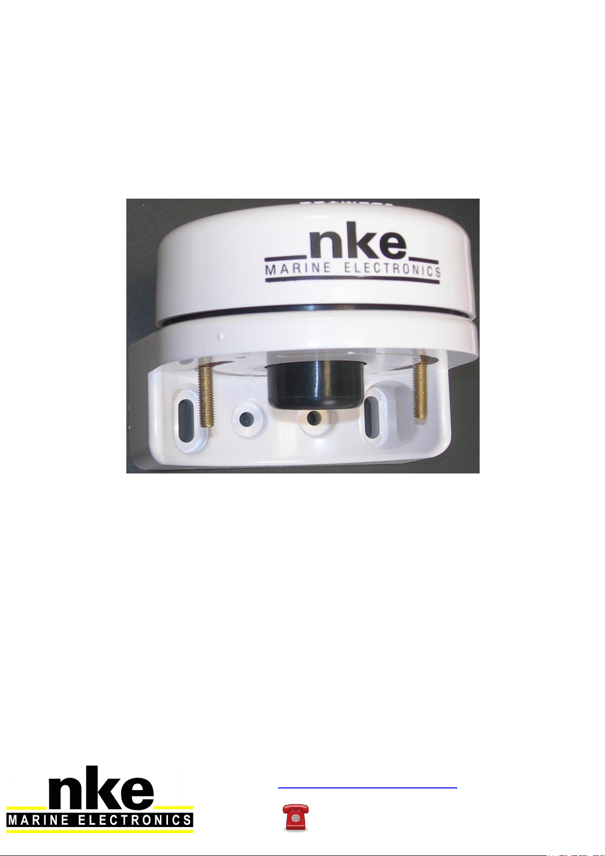
REGATTA Compass Sensor
Product reference: 90-60-396
USER MANUAL
&
INSTALLATION GUIDE
Rev : 1

2
46_Regatta_Compass_Interface_um_EN_14
CONTENTS
1 OPERATION ......................................................................................................................... 3
PRESENTATION ........................................................................................................................... 3
LIST OF CHANNELS DISPLAYED ...................................................................................................... 4
ALARMS SETTING ......................................................................................................................... 4
FILTERING OF THE CHANNELS ..................................................................................................... 4
DIAGNOSTIC FOR 1ST LEVEL TROUBLESHOOTING. ........................................................................... 5
2 SENSOR CALIBRATION ...................................................................................................... 6
OFFSET SETTING ......................................................................................................................... 6
COMPASS AUTOCOMPENSATION .................................................................................................... 8
3 INSTALLATION .................................................................................................................... 9
LIST OF ACCESSORIES ................................................................................................................. 9
INSTALLATION PRECAUTIONS ........................................................................................................ 9
INSTALLING THE COMPASS ON A VERTICAL SURFACE ..................................................................... 10
CONNECTION TO THE TOPLINE BUS.............................................................................................. 14
3
46_Regatta_Compass_Interface_um_EN_14
1 OPERATION
PRESENTATION
The Regatta Compass sensor is a measuring instrument that provides the magnetic
heading, heel and pitch of the boat.
It is connected to the Regatta Compass interface of your TOPLINE installation.
The sensor is equipped with a 10-meter cable, a mounting bracket, two screws and the Regatta
Compass interface.
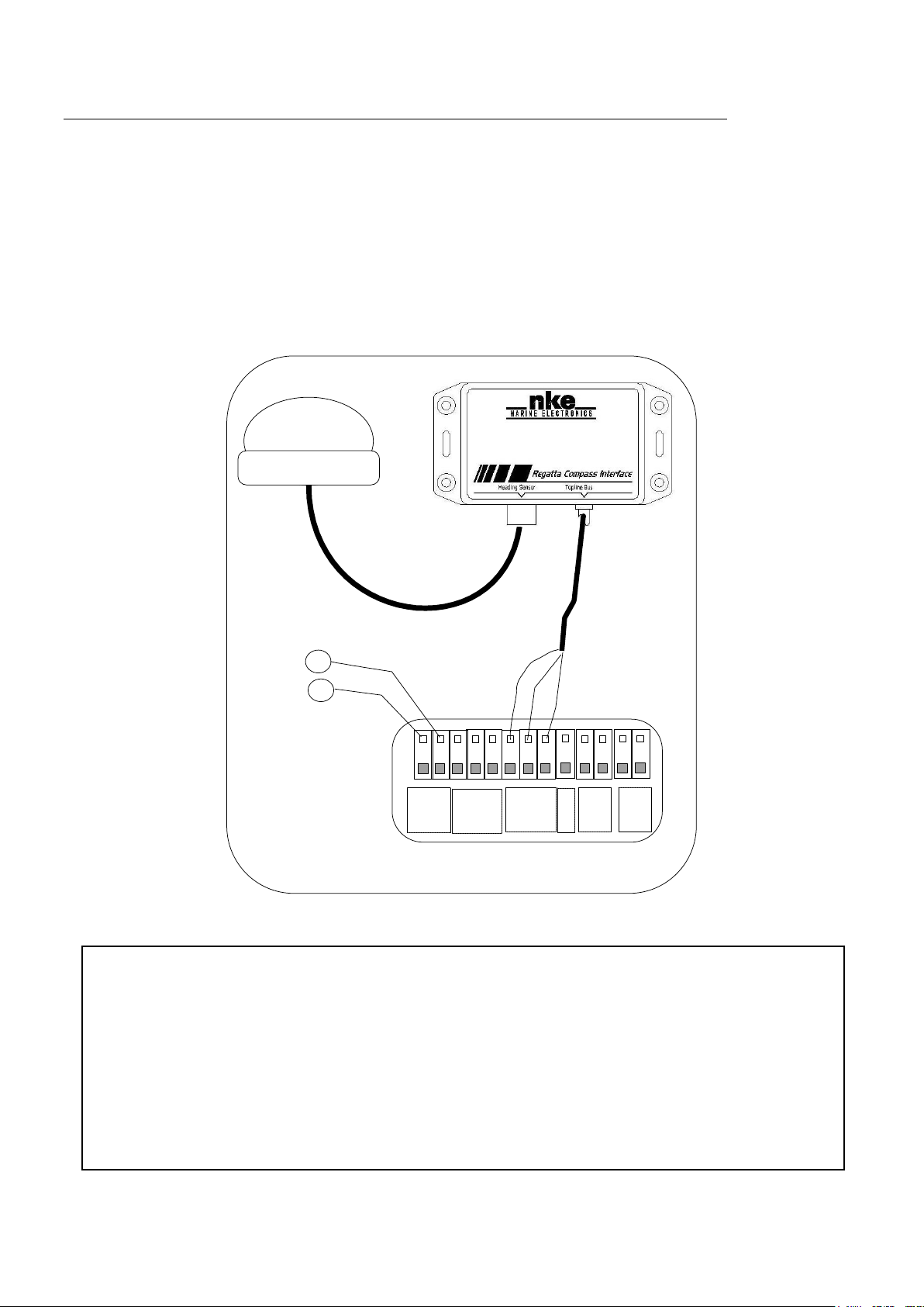
architecture of the installation
+
12VDC white
DATA black
-
Terminal box
90-60-417
12VDC power supply
REGATTA COMPASS
IMPORTANT
Please read this guide completely before starting the installation.
Any electrical connection on the TOPLINE bus must be carried out using terminal box
90-60-121. Only use TOPLINE bus cable 20-61-001.
Any intervention on the TOPLINE bus must be carried out with the installation power
switched off.
For channel settings, please refer to the user guide of your TOPLINE display.
4
46_Regatta_Compass_Interface_um_EN_14
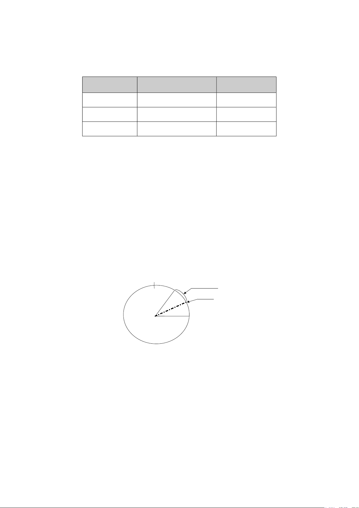
Base
Range
0°
LIST OF CHANNELS DISPLAYED
The Regatta compass, connected to the TOPLINE bus of your installation, creates the
channel below. They are accessible from the displays of the TOPLINE range.
Channel Display Unit
Magnetic heading MAGN HDG 245° Degree
Heel HEEL Degree
Pitch PITCH Degree
ALARMS SETTING
The setting of an alarm enables you to monitor the magnetic heading you are following.
When the preset angle range is exceeded, a warning message is displayed and an audible
alarm is activated.
There is no alarm for heel and pitch.
Procedure
Display the magnetic heading channel.
Select the BASE sub-channel and enter the value of the reference heading selected for the
alarm.
Select the RANGE sub-channel and enter the tolerance on either side of the reference heading.
To cancel the alarm, enter the value 0 in the RANGE sub-channel.
Thus, the setting of an alarm on the compass will allow you to effectively monitor the heading
consistency of your boat.
To activate the alarms, please refer to the user guide of your display.
FILTERING OF THE CHANNELS
The level of filtering of a channel determines the frequency of update of the data
displayed. For example, in rough sea when the boat moves significantly, it is useful to increase
the filtering of the magnetic heading channel to stabilise the value displayed. Conversely, in
calm sea, low filtering will be preferable to obtain a fast response of the display.
Filtering is adjustable between 1 and 32, and the default value is 8. The lower this value is, the
higher the frequency of update is.

5
46_Regatta_Compass_Interface_um_EN_14
Please refer to the user guide of your display to adjust the filter setting.
Technical specifications
Power supply: 10 to 16VDC
Power consumption: <200mA (Compass & Interface)
Resolution: 0.1° (with Processor)
Roll and pitch measurement range: +/- 50°
Tightness: IP66
Weight: 270g
Operating temperature: -10°C to +50°C
Storage temperature: -20°C to +60°C
DIAGNOSTIC FOR 1ST LEVEL TROUBLESHOOTING.
This chapter can help you rapidly resolve minor problems which do not require the
intervention of a specialist. Before contacting technical support, please check the
troubleshooting table below.
Problem Possible causes and solutions
The Topline installation does not detect the compass.
The bus cable is not or is badly connected to the terminal box : check the
plugging inside the terminal box. Check the state of the cables : they
must not show any sign of wear or cut.
The magnetic heading displayed is very different from that
indicated by the steering compass. Check that no equipment likely to disrupt the steering compass of your
boat or the fluxgate compass is in the vicinity: please consult the list in
the installation chapter.
Check that the steering compass of your boat is compensated.
Carry out a calibration of the compass.
If you do not manage to solve the problem, please contact your distributor.

6
46_Regatta_Compass_Interface_um_EN_14
2 SENSOR CALIBRATION
The Regatta Compass is adjusted at the factory. However, an offset adjustment is
required to adapt the sensor to the specificities of your boat and to obtain an optimum
measurement accuracy. Follow the calibration procedure below, while visualising the settings
on a display: please refer to the user guide of your display.
OFFSET SETTING
2.1.1 Principle
After the installation, it is necessary to adjust the OFFSET of the Regatta Compass so
that the magnetic heading displayed is identical to the true magnetic heading.
In order to do that, you must carry out an actual test at sea with your boat. Take the GPS unit of
your boat as reference, and make sure there is no current and the sea is calm in the area
chosen for this test. Follow a set bottom (magnetic) heading and note the heading shown by the
magnetic heading channel of your display. Then, deduce the difference between the steering
compass and the magnetic heading displayed : this value is the correction offset of the
Regatta compass.
2.1.2 Procedure for setting the offset coefficient (the default offset value is 0):
Select the calib offset sub-channel of the magnetic heading channel.
Enter the new calculated offset coefficient and validate using the enter key. The new
setting will be saved to the memory.
2.1.3 Procedure for setting the heel offset (the default offset value is 0):
Select the sub-channel offset calib of the Heel channel.
Enter the new offset coefficient and confirm by pressing enter. The new setting will be
saved to the memory.
2.1.4 Procedure for setting the pitch offset (the default offset value is 0):
Select the sub-channel offset calib of the Pitch channel.
Enter the new offset coefficient and confirm by pressing enter. The new setting will be
saved to the memory.
CAUTION:
- If your steering compass is taken as reference, it must be compensated (calibrated) so
that the calibration is correct.
- Before setting the offset, you must adjust the mechanical position of the compass:
refer to
the installation chapter.

7
46_Regatta_Compass_Interface_um_EN_14
Please refer to the user guide of your display to perform the setting.

8
46_Regatta_Compass_Interface_um_EN_14
COMPASS AUTOCOMPENSATION
On some boats, the Regatta Compass may be strongly disrupted by its environment.
Despite a careful installation and an offset properly adjusted, an important difference remains
between the magnetic heading displayed and the true magnetic heading, throughout the
measurement range between 0 and 359°. In this case, you can perform an autocompensation
of the Regatta Compass to achieve an acceptable level of accuracy.
2.1.5 Autocompensation principle
The operation consists in executing a perfect circle with your boat at a rigorously
constant speed. Thus, your Regatta Compass will be accurately corrected between 0 and
359°.
2.1.6 Autocompensation procedure for the Regatta Compass
In order to achieve a successful autocompensation, you must sail:
- On a smooth sea, with no current,
- Away from large magnetic masses such as cargo ships, buoys, metallic pontoons,…
- At a constant speed of about 2 or 3 knots.
1. Display the magnetic heading channel.
2. Launch the “autocompensation” mode according to the procedure described in the user
guide of your display.
3. Start to describe the circle then launch the autocompensation procedure.
4. One circle is enough to perform the autocompensation correctly.
5. The display then sends out a message to the user indicating that the autocompensation is
successful. The number 3 for the Gyropilot and the number 3000 alternately with dashes
for the other displays (Performance, TL25 and SL50).
6. Exit the autocompensation mode.
Please refer to the user guide of your display to perform the autocompensation procedure.
Should there be a problem during autocompensation, the display will notify the user of the
cause of the fault indicating alternately, for 5 seconds, the message PANNE with the following
code :
- code 11: Failure through timeout (> 5 minutes) or excessively slow rotation (< 30 sec / 45°).
- code 12: Failure through excessive heel.
- code 13: Any other error.
In case of autocompensation error, the measurements are not saved to the memory and the
sensor resumes its normal operating mode.
CAUTION: the autocompensation operation of the Regatta Compass requires precision in
the execution of the circle: it must be done in less than 5 minutes at a constant speed of 2
to 3 knots. If you cannot maintain these two criteria, the autocompensation will not be
successful.

9
46_Regatta_Compass_Interface_um_EN_14
3 INSTALLATION
Before starting the installation, take the time to select the most appropriate location for
the sensor. Indeed, the Regatta Compass and its TOPLINE interface, just like the steering
compass of your boat, is sensitive to metal masses, the movements of the boat and the
disturbances caused by electrical appliances. Although it can be autocompensated, the
installation must be carefully carried out in order to achieve an optimum level of accuracy.
LIST OF ACCESSORIES
- TOPLINE Terminal box: 90-60-121
- TOPLINE bus cable: 20-61-001
INSTALLATION PRECAUTIONS
The location of the sensor must be:
- as close as possible to the pitch and roll centres of the boat; the closer it is to the centre of
gravity, the more stable the measurement will be.
- more than one metre away from onboard magnetic compasses (to avoid a mutual
disturbance).
- as far as possible from onboard magnetic masses.
- With the least amount of vibration.
- Do not install the compass inside boats with a steel hull. A position on the mast can be
considered on this type of boat.
Below is a list of equipment likely to disrupt a fluxgate compass:
- The keel of the sailing boat (when it is made out of cast iron or steel).
- The radio and radar equipment.
- The boat’s engine.
- Generators and battery chargers.
- Voltage regulators.
- Electrical motors.
- Tool boxes and anchors.
- The electrical windlass.
- High voltage electrical cables.
Before installing the Regatta Compass, you can check that the location will not be disrupted by
following the procedure below:
Place a bearing compass at the selected location. Then, with your boat, execute a full 360°
circle in order to compare the information provided by the steering compass and the boarding
compass. If the variations are less than 10°, the location is suitable.
Also make sure you will be able to run the cable without being too close to the high amperage
cables, such as those of the generator motor and batteries. Keep a distance of at least 1 metre
between the cables.
CAUTION: the metal spanner that you use when screwing the nut disrupts the compass.
Move the spanner away from the compass when you check the magnetic heading
displayed.

10
46_Regatta_Compass_Interface_um_EN_14
INSTALLING THE COMPASS ON A VERTICAL SURFACE
Using a spirit or electronic level, mark the mounting holes of the mounting bracket at the
chosen location.
Drill the 4mm holes and screw the self-tapping stainless steel screws.
Drill 6mm holes for the mounting bracket centre screws.
Sensor preparation
There are two ways to install the sensor:
Using threaded pins:
This method is easier for the user because it allows the position of the compass to be adjusted.
However, these screws will protrude under the sensor by about 20mm, which can prevent the
compass from being installed in a limited space.
Install the cable and the seal on the compass.
Screw the pins onto the compass.
Spirit level
Mounting bracket
Vertical oblong hole
Stainless steel screws (4)

11
46_Regatta_Compass_Interface_um_EN_14
Cable
Nut
Seal
Compass
Threaded pin
Mounting
bracket
Positioning
screws
Washers
Washers
Screw
Using screws:
The screws allow the space needed for the compass and its mounting bracket to be optimised.
Installation of the compass
Pass the connector of the compass through the seal.
Connect the cable to the compass.
Connector
Seal
Serial
number
Connector
Arrow
pointing
forward
Compass
Threaded pin

12
46_Regatta_Compass_Interface_um_EN_14
Insert the seal onto the compass so as to match the mounting holes between the compass and
the seal.
Pass the cable through the mounting bracket and place the compass onto its mounting bracket.
Line up the “Forward” arrow with the centreline of the boat.
Screw the mounting screws or nuts, depending on the chosen solution.
Make sure the axis of the compass has not moved while tightening the screws or nuts.
Installing the compass on a horizontal surface
Pass the connector of the compass through the seal.
Connect the cable to the compass.
Insert the seal onto the compass so as to match the mounting holes between the compass and
the seal.
Drill the holes for the threaded mounting pins of the compass using a 6mm drill bit.
Drill the cable hole using a 38mm drill bit.
Pass the cable through the hole.
Position the compass on the surface.
Screw the threaded pins onto the compass.
Place the flat washers and lock washers on the pins.
Hand screw the nuts onto the pins.

13
46_Regatta_Compass_Interface_um_EN_14
Positioning arrow
Connector
Mounting surface
Lock washer
Compass
Flat washer
Threaded
pin Connector
Serial
number
Connector
Nut
Seal

14
46_Regatta_Compass_Interface_um_EN_14
CONNECTION TO THE TOPLINE BUS
1. Run the compass bus cable to the interface of the Regatta Compass of your installation.
2. Connect the bus cable of the Regatta compass interface to a terminal box.
3. Connect the bus cable inside the terminal box:
If you reduce the length of the bus cable, strip and galvanise the wires before connecting them
inside the terminal box.
+
12VDC white
DATA black
-
Terminal box
90-60-417
12VDC power supply
REGATTA COMPASS

15
46_Regatta_Compass_Interface_um_EN_14
NOTES
_____________________________________________________________________________________________________
_____________________________________________________________________________________________________
_____________________________________________________________________________________________________
_____________________________________________________________________________________________________
_____________________________________________________________________________________________________
_____________________________________________________________________________________________________
_____________________________________________________________________________________________________
_____________________________________________________________________________________________________
_____________________________________________________________________________________________________
_____________________________________________________________________________________________________
_____________________________________________________________________________________________________
_____________________________________________________________________________________________________
_____________________________________________________________________________________________________
_____________________________________________________________________________________________________
_____________________________________________________________________________________________________
_____________________________________________________________________________________________________
_____________________________________________________________________________________________________
_____________________________________________________________________________________________________
_____________________________________________________________________________________________________
_____________________________________________________________________________________________________

16
46_Regatta_Compass_Interface_um_EN_14
NOTES
_____________________________________________________________________________________________________
_____________________________________________________________________________________________________
_____________________________________________________________________________________________________
_____________________________________________________________________________________________________
_____________________________________________________________________________________________________
_____________________________________________________________________________________________________
_____________________________________________________________________________________________________
_____________________________________________________________________________________________________
_____________________________________________________________________________________________________
_____________________________________________________________________________________________________
_____________________________________________________________________________________________________
_____________________________________________________________________________________________________
_____________________________________________________________________________________________________
_____________________________________________________________________________________________________
_____________________________________________________________________________________________________
_____________________________________________________________________________________________________
_____________________________________________________________________________________________________
_____________________________________________________________________________________________________
_____________________________________________________________________________________________________
_____________________________________________________________________________________________________
This manual suits for next models
1
Table of contents
Other NKE Accessories manuals


