manuals.online logo
Brands
  1. Home
  2. •
  3. Brands
  4. •
  5. Johnson Controls
  6. •
  7. Accessories
  8. •
  9. Johnson Controls B401BH User manual

Johnson Controls B401BH User manual

JCI-60130:A2 • 9/16/09 — Page 1 of 2
B401BH and B401BHA
Conventional Bases with Sounder
JCI-60130:A2
General
The System Sensor B401BH(A) Base with Sounder is used
with conventional 400 Series two-wire plug-in smoke detec-
tors. Refer to the associated control panel manual for more
information on detector heads.
NOTE: Only compatible UL/ULC-approved smoke detectors may
be used with the B401BH(A).
Features
• Sound output greater than 90 dBA measured in anechoic
room at 10 feet (3.048 m), 24 volts. 85 dBA minimum mea-
sured in a UL reverberant room.
• An alarm delay of approximately 10 seconds is built into
the B401BH(A). This delay is present whether the control
signal comes from the sensor or from reversing the exter-
nal power supply polarity.
Applications
The B401BH(A) base is intended for use with conventional
plug-in systems. See systems literature for maximum allow-
able number of units per loop.
Construction and Operation
The B401BH(A) requires an external 24 VDC supply with
reverse polarity capability. The connections of the external
supply (terminals 1 and 2) and the communication/initiating
loop (terminals 3, 4, and 5) are isolated in the B401BH(A) to
prevent electrical interaction between them.
NOTE: When not used as a supplementary evacuation system,
the external 24 VDC supply shall be treated as a component of the
main power supply system and shall fall under the requirements of
the main power supply system per NFPA 72.
When the detector head’s visible LEDs are latched ON for
approximately 10 seconds, the base horn sounds. A loop of
horns can be made to sound with the polarity reversal of the
external supply.
Installation
NFPA 72 and NEMA guidelines should be observed. For
installation in Canada, refer to CAN/ULC S524, Standard
for the Installation of Fire Alarm Systems and CEC Part 1,
Sec. 32.
Units must be mounted directly to a 4.0" (101.6 mm) square
electrical box, minimum 1.5" (38.1 mm) deep, using the sup-
plied mounting kit. A maximum space of 0.125" (3.175 mm)
from outside edge of electrical box to the inside edge of the
drywall or ceiling tile is allowable.
A flangeless plug-in base is used to attach detectors to the
B401BH(A) base with sounder.
Before installing detectors, please read Guide for Proper Use
of System Smoke Detectors, document number 156-407-00,
which provides detailed information on detector spacing,
placement, zoning, wiring, and special applications.
B601BH(A) TERMINALS:
1. External Supply Positive (+)
2. External Supply Negative (–)
3. Negative (–) V In
4. Positive (+) V In and V Out
5. Negative (–) V Out
NOTE: Terminals 3, 4, and 5 are used for the communication/initi-
ating circuit.
Specifications
Base diameter: 6.0" (152.4 mm).
Base height (less base & sensor): 0.75" (19.05 mm).
Weight: 0.3 lbs. (140 grams).
Operating temperature range: 14°F to 140°F (–10°C to
+60°C).
Operating humidity range: 10% to 95% relative humidity,
non condensing.
Sounder in UL reverberant room: 85 dBA minimum.
Sounder in anechoic room: > 90 dBA @ 10 feet (3 m), 24
volts.
Electrical Ratings
Wiring: Tw o - wi r e .
EXTERNAL SUPPLY:
Voltage: 17 to 32 VDC.
Standby current: 1.0 mA maximum.
Alarm current: 15 mA maximum.
Maximum ripple voltage: 10% of supply voltage.
Startup capacitance: 200 μF.
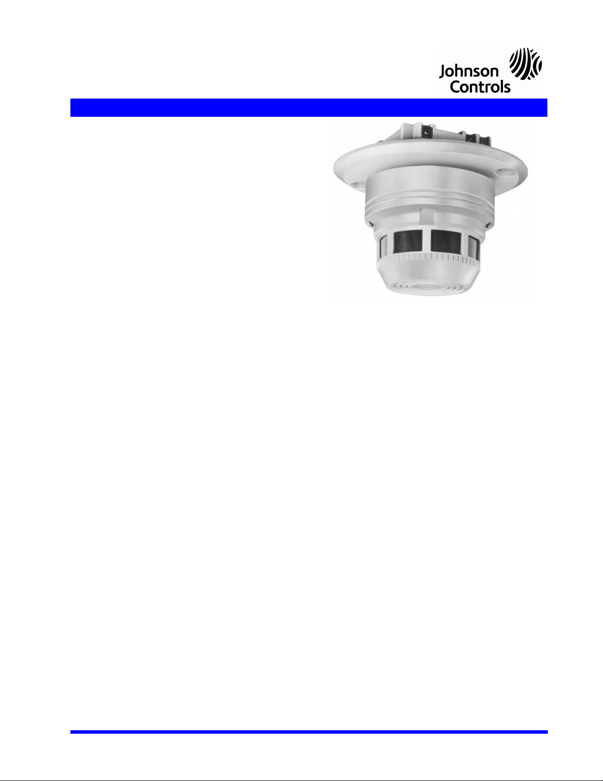
4786pho1.jpg
B401BH sounder assembly,
shown with a 2541 photo detector
Page 2 of 2 — JCI-60130:A2 • 9/16/09
System Sensor® is a registered trademark of Honeywell International Inc.
©2009. All rights reserved. Unauthorized use of this document is strictly pro-
hibited.
This document is not intended to be used for installation purposes.
We try to keep our product information up-to-date and accurate.
We cannot cover all specific applications or anticipate all requirements.
All specifications are subject to change without notice.
For more information, contact Johnson Controls Field Support Center.
507 East Michigan Street, Milwaukee, WI 53202 www.johnsoncontrols.com
Made in the U.S. A.
COMMUNICATION/INITIATING LOOP SUPPLY:
Current draw from remote output of detector to turn horn ON:
• Conventional system requires 600 μA maximum.
• Intelligent system requires 700 μA maximum.
For all other system electrical ratings, consult the appropriate
base manual.
NOTE: 1) No auxiliary devices may be used in conjunction with
the B401BH(A). 2) High-current relays are needed to switch the
polarities of the external power supply. The B401BH(A) draws up
to 1.0 mA in standby and 15 mA in alarm (sounding condition)
from the external supply. The current capacity during standby
can be up to 99 mA (1.0 mA per base) without any horns sounding
(plus an additional 75 mA to 150 mA from local sensor control) or
up to 1.5 A with a polarity reversal and 99 mA with horns sounding.
Agency Listings and Approvals
These listings and approvals apply to the B401BH(A). In
some cases, certain modules or applications may not be
listed by certain approval agencies, or listing may be in pro-
cess. Consult factory for latest listing status.
•UL Listed: file S911.
•ULC Listed: file CS308.
•CSFM approved: file 7300-1209:128.
•Maryland State Fire Marshal approved: Permit # 1985.
•MEA approved: file 205-94-E.
Product Line Information
B401BH: Sounder base assembly, includes pre-assembled
sounder and B401 base.
B401BHA: Same as above with ULC listing.
B401: Plug-in flangeless base for 400 Series detectors.
B401A: Same as above with ULC listing.
Face of B401BH(A) detector base
with sounder
Back of detector base with sounder
4786d1.wmf 4786d2.wmf

This manual suits for next models

1

Other Johnson Controls Accessories manuals

Johnson Controls WRZ-SST-120 User manual

Johnson Controls

Johnson Controls WRZ-SST-120 User manual

Johnson Controls GS3000 User manual

Johnson Controls

Johnson Controls GS3000 User manual

Johnson Controls THM-R2A User manual

Johnson Controls

Johnson Controls THM-R2A User manual

Johnson Controls 2951J-COPTIR User manual

Johnson Controls

Johnson Controls 2951J-COPTIR User manual

Johnson Controls NS Series User manual

Johnson Controls

Johnson Controls NS Series User manual

Johnson Controls WRZ-SST-110 User manual

Johnson Controls

Johnson Controls WRZ-SST-110 User manual

Johnson Controls LN Series User manual

Johnson Controls

Johnson Controls LN Series User manual

Johnson Controls 2951J User manual

Johnson Controls

Johnson Controls 2951J User manual

Johnson Controls NS Series User manual

Johnson Controls

Johnson Controls NS Series User manual

Johnson Controls NS Series User manual

Johnson Controls

Johnson Controls NS Series User manual

Johnson Controls TMZ1600 User manual

Johnson Controls

Johnson Controls TMZ1600 User manual

Johnson Controls TE-7800 Series User manual

Johnson Controls

Johnson Controls TE-7800 Series User manual

Johnson Controls NS-ATV7003-0 User manual

Johnson Controls

Johnson Controls NS-ATV7003-0 User manual

Johnson Controls 5951J User manual

Johnson Controls

Johnson Controls 5951J User manual

Johnson Controls NS8000 Series User manual

Johnson Controls

Johnson Controls NS8000 Series User manual

Johnson Controls WRZ Series User manual

Johnson Controls

Johnson Controls WRZ Series User manual

Johnson Controls WRZ Series User manual

Johnson Controls

Johnson Controls WRZ Series User manual

Johnson Controls NS8000 Series User manual

Johnson Controls

Johnson Controls NS8000 Series User manual

Johnson Controls NS Series User manual

Johnson Controls

Johnson Controls NS Series User manual

Johnson Controls NS-DTN7043-2 User manual

Johnson Controls

Johnson Controls NS-DTN7043-2 User manual

Johnson Controls NS Series User manual

Johnson Controls

Johnson Controls NS Series User manual

Johnson Controls NS Series User manual

Johnson Controls

Johnson Controls NS Series User manual

Johnson Controls WRZ-TTB0000-5 User manual

Johnson Controls

Johnson Controls WRZ-TTB0000-5 User manual

Johnson Controls NS-AP Series User manual

Johnson Controls

Johnson Controls NS-AP Series User manual

Popular Accessories manuals by other brands

INNOBIZ 2141 Instructions for use

INNOBIZ

INNOBIZ 2141 Instructions for use

CARLO GAVAZZI PD140 user manual

CARLO GAVAZZI

CARLO GAVAZZI PD140 user manual

Flavour Blaster MINI user manual

Flavour Blaster

Flavour Blaster MINI user manual

ZEN LILI instruction manual

ZEN

ZEN LILI instruction manual

Werkzeyt B29873 quick start guide

Werkzeyt

Werkzeyt B29873 quick start guide

wtw FDO 700 IQ F operating manual

wtw

wtw FDO 700 IQ F operating manual

Siro SL-PIR35-K1 instruction manual

Siro

Siro SL-PIR35-K1 instruction manual

Vega VEGAPULS 69 operating instructions

Vega

Vega VEGAPULS 69 operating instructions

Burkert MS06 Series operating instructions

Burkert

Burkert MS06 Series operating instructions

IFM efector200 OOF Series operating instructions

IFM

IFM efector200 OOF Series operating instructions

Wenglor P2KL Series operating instructions

Wenglor

Wenglor P2KL Series operating instructions

Ericsson RBS 6401 installation guide

Ericsson

Ericsson RBS 6401 installation guide

Fire-Lite Alarms SD355CO Installation and maintenance instructions

Fire-Lite Alarms

Fire-Lite Alarms SD355CO Installation and maintenance instructions

Astronomy Technologies Astro-Tech AT6RC quick start guide

Astronomy Technologies

Astronomy Technologies Astro-Tech AT6RC quick start guide

Traceable 3140 instructions

Traceable

Traceable 3140 instructions

Carefree Campout owner's manual

Carefree

Carefree Campout owner's manual

Techmar 6156011 quick start guide

Techmar

Techmar 6156011 quick start guide

Northern Lights Lugger M944W Assembly instructions

Northern Lights

Northern Lights Lugger M944W Assembly instructions

manuals.online logo
manuals.online logoBrands
  • About & Mission
  • Contact us
  • Privacy Policy
  • Terms and Conditions

Copyright 2025 Manuals.Online. All Rights Reserved.