Set the switching pressure with two teach pressures TP1/TP2
Note
The sequence of the teach pressures for the switching pressure setting affects
the switching element function (normally closed contact/normally open contact)
of the SDE5.
• Take the following relationship into account:
TP1 ‹ TP2: Programming as NO contact
TP1 › (TP2 + 2 % Full Scale): Programming as NC contact
1. Note down the teach pressures TP1 and TP2.
2. Pressurize the SDE5 with the first teach pressure TP1.
3. Press the Edit button (› 2 s) until the LED flashes.
4. Let go of the Edit button.
The current teach pressure TP1 is saved.
The LED flashes.
5. Pressurize the SDE5 with the second teach pressure TP2.
6. Press the Edit button until the LED stops flashing.
7. Let go of the Edit button.
The current teach pressure TP2 is saved.
8. Ensure that there is power supply for at least 10 seconds.
9. Carry out a test run with various pressures to ascertain whether the SDE5 switches
as desired. When the switching signal is emitted, the LED also lights up.
Signal curve over the applied pressure p with switching points
The diagrams for NO (normally open contact, TP1 < TP2) and NC (normally closed
contact, TP1 ‹ TP2 + 2 % Full Scale)), show the relationship between teach
pressure, switching pressure and hysteresis, (Fig. 15).
6Operation
Warning
Danger of injury from high temperatures.
Extreme pneumatic conditions (high cycle rate with large pressure amplitude)
can heat the device over 80 °C.
• Select the operating conditions (in particular the ambient temperature,
pressure amplitude, cycle rate) such that the device does not heat up above
the maximum permitted operating temperature.
• Comply with the operating conditions.
• Switch on the operating voltage.
The device is working in the RUN mode (basic status).
LED display Meaning
LED illuminated yellow SDE5-…-P/-N-…(switching output): pressure p > switching pressure
LED not lit SDE5-…-P/-N-…(switching output): pressure p < switching pressure
LED flashes quickly Teach procedure (Fig. 12)
LED flashes slowly Only SDE5-…-FP: display and setting of the switching function
LED illuminated green Only SDE5-…-V (analogue output): ready status (RUN mode)
Fig. 17
7 Maintenance and care
Clean the SDE5 on the outside
1. Switch off the operating voltage.
2. Switch off the compressed air.
3. Clean the outside of the SDE5 with a soft cloth.
Permissible cleaning agents are soapy water (max. +50 °C) and all non-abrasive
agents.
8 Disassembly
1. Switch off the operating voltage.
2. Switch off the compressed air.
3. Disconnect the electrical and pneumatic connections from the SDE5.
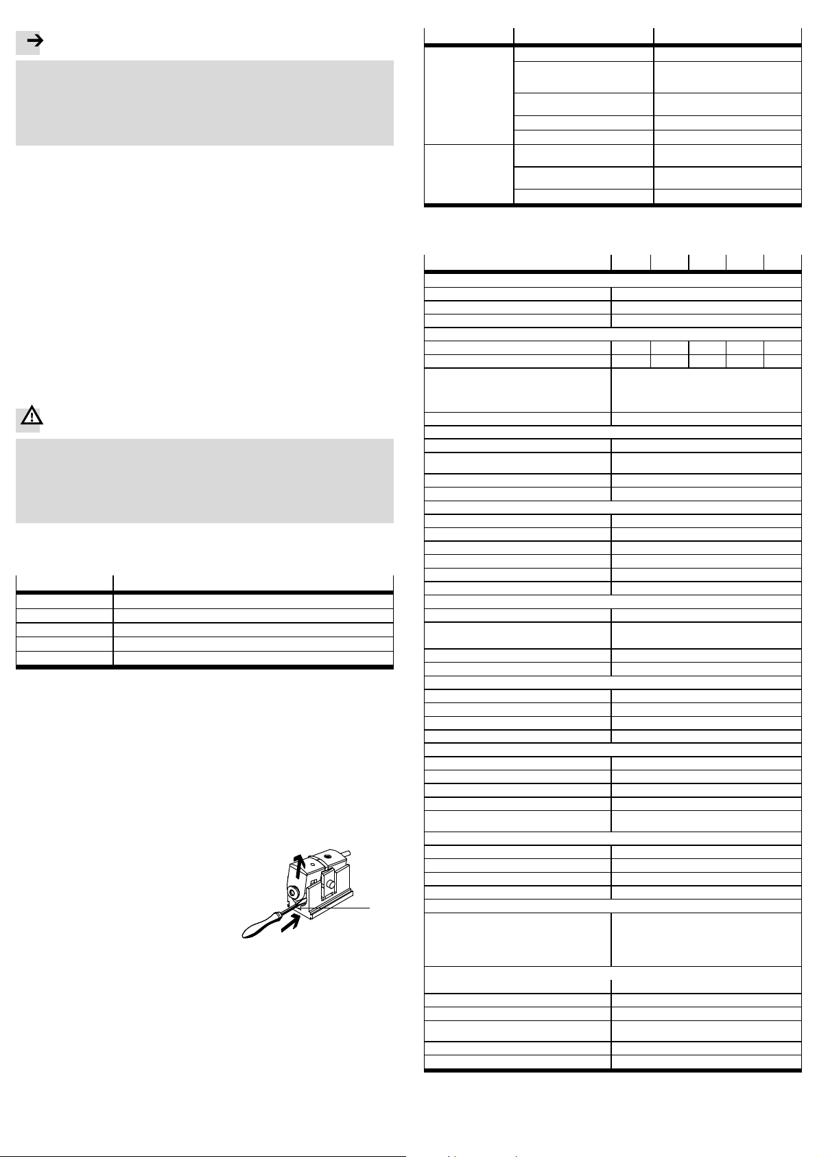
4. Release the SDE5 from the wall holder.
For this, slide a screwdriver into the
groove 1and prise the SDE5 out of the
wall holder.
1
Fig. 18
9 Troubleshooting
Malfunction Possible cause Remedy
No LED display Pressure p < switching pressure SP Regular operating status (Fig. 17)
No power supply or there is a
non-permissible operating voltage Switch on power supply/adhere to
the permitted operating voltage
range
Connections swapped
(incorrect polarity) Wire the SDE5 as shown in the
circuit diagram
Pressure failure Eliminate pressure failure
SDE5 defective Replace device
LED display or
switching output
does not react in
accordance with the
settings made
Short circuit or overload at the
output Eliminate short circuit/overload
Incorrect switching point
(e.g. at 0 bar) Repeat teach procedure
SDE5 defective Replace device
Fig. 19
10 Technical data
Type SDE5 -V1 -B2 -D2 -D6 -D10
General
Certification C-Tick, c UL us – Recognized (OL)
CE marking (declaration of conformity) in accordance with EU EMC Directive
Note on materials RoHS-compliant
Input signal/measuring element
Pressure measuring range
1)
[bar] 0…–1 –1 … 1 0…2 0…6 0…10
Max. overload pressure [bar] 5 5 6 15 15
Operating medium Compressed air in accordance with ISO 8573-1:
2010
[7:4:4] – Lubricated operation possible
Temperature of medium [°C] 0 … +50
Ambient temperature [°C] 0…+50
Output, general
Repetition accuracy [% full scale] ± 0.3 (short time)
Temperature coefficient [% full
scale/Kelvin] Max. ±0.05
Protection against short circuit Yes
Protection against overloading Yes
Switching output
Accuracy [% full scale] Max. ±0.5
Switching time (on/off) [ms] 2 (typical)/4 (max.)
2)
Maximum output current [mA] 100
Capacitive load max. DC [nF] 100
Voltage drop [V] max. 1.8
Inductive protective circuit Adapted to MZ, MY, ME coils
Analogue output
Output characteristic curve
1)
[V] 0…10
Accuracy [% full scale] ±3 (room temperature: 20 … 25 °C)
[% full scale] max. ±4 (room temperature: 0 … 50 °C)
Rise time [ms] 5 (typical) with ohmic load
Min. load resistance [kΩ] 2
Electronics
Operating voltage range [V DC] 15 … 30
Idle current [mA] max. 34
Ready-state delay [ms] š10
Reverse polarity protection For all electrical connections
Electromechanics
Max. cable length [m] 30
Information on cable sheath material PUR
Informationonplughousingmaterial Brass (nickel-plated, chromed)
Cable diameter [mm] 2.9
Nominal cross section of
conductor [mm
2
]0.14
Mechanics
Mounting position As desired, preferably vertical
3)
Information on housing material Polyamide (POM) reinforced
Information on keyboard material Polyamide (POM) reinforced
Information on fibre-optic cable material PA
Display/operation
Setting range threshold values:
– Switching pressure [% full scale] 0 … 100 (recommended operating range 1 … 99)
–Hysteresis(mode2) [% full scale] 0 … 100 (recommended operating range 1 … 99)
– Hysteresis (mode 1, 3) [% full scale] 2 (permanently set)
Immission/emission
Storage temperature [°C] –20 … +80
Protection class (as per EN 60529) IP40
Protection class (as per DIN VDE 0106-1) III
Resistance to shocks (as per EN 60068-2) 30 g acceleration with 11 ms duration
(half-sine)
Vibration resistance (as per EN 60068-2) 0.35 mm travel, 5 g acceleration at 10 … 150 Hz
Corrosion resistance class CRC 2
1) Starting value…Final value.
2) Switching times do not apply with additional function activated ...- TF (filter function).
3) No condensed water should be allowed to accumulate in the pressure measuring cell.