pizzato ST Series User manual

6/30
Pizzato Elettrica Srl
via Torino, 1
36063 MAROSTICA (VI)
ITALY
e-mail: [email protected]
web site: www.pizzato.com
Phone: +39.0424.470.930
ZE FOG131B21-EU
1 INFORMATION ON THIS DOCUMENT
1.1 Function
The present operating instructions provide information on installation, connection and
safe use for the following articles: ST G••••••,ST H••••••.1.2 Target audience
The operations described in these operating instructions must be carried out by
qualified personnel only, who are fully capable of understanding them, and with the
technical qualifications required for operating the machines and plants in which the
safety devices are to be installed.
1.3 Application field
These operating instructions apply exclusively to the products listed in paragraph
Function, and their accessories.
1.4 Original instructions
The Italian language version is the original set of instructions for the device. Versions
provided in other languages are translations of the original instructions.
2 SYMBOLS USED
This symbol indicates any relevant additional information.
Attention: Any failure to observe this warning note can cause damage or mal-
function, including possible loss of the safety function.
3 DESCRIPTION
3.1 Device description
The safety device described in these operating instructions is defined as a coded,
type-4 interlocking device without contact acc. to EN ISO 14119.
The safety sensors with RFID technology to which these operating instructions
refer are safety devices designed and implemented for the control of gates, guards,
enclosures, and doors in general, which are installed to protect dangerous parts of
machines without inertia.
3.2 Intended use of the device
- The device described in these operating instructions is designed to be applied on
industrial machines (as defined in the Machinery Directive) for state monitoring of
movable guards.
- The direct sale of this device to the public is prohibited. Installation and use must be
carried out by qualified personnel only.
- The use of the device for purposes other than those specified in these operating
instructions is prohibited.
- Any use other than as expressly specified in these operating instructions shall be
considered unintended by the manufacturer.
- Also considered unintended use:
a) using the device after having made structural, technical, or electrical modifications
to it;
b) using the product in a field of application other than as described in paragraph
TECHNICAL DATA.
4 INSTALLATION INSTRUCTIONS
Attention: Installing a protective device is not sufficient to ensure operator safety
or compliance with machine safety standards or directives. Before installing a protec-
tive device, perform a specific risk analysis in accordance with the key health and
safety requirements in the Machinery Directive.The manufacturer guarantees only the
safe functioning of the product to which these operating instructions refer, and not the
functional safety of the entire machine or entire plant.
4.1 Actuation directions
The device can be actuated by approaching the actuator from any direction.
The centring symbols indicated on the device and actuator must face one
another when the guard is closed, regardless of actuation direction.
Article ST G••••••-G•TArticle ST H••••••-H•T4.2 Selection of the actuator type
Attention: The device is available with two types of RFID actuator: with high
(articlesSM•1T)orlow(articlesSM•0T)levelofcoding.Ifthechosenactuatorhasa low level of coding, the additional specifications given in Std. EN ISO 14119:2013
paragraph 7.2 must be applied during the installation.
Attention: If the chosen actuator has a low level of coding, any other low level
coded actuators present in the same place where the device has been installed must
be segregated and kept under strict control in order to avoid any bypassing of the
safety device. If new low level coded actuators are fitted, the original low level coded
actuators must be disposed of or rendered inoperable.
It is advisable to use high coding level actuators to make the installation safer
and more flexible. In this way, no device screening, installation in inaccessible zones
or other requirements specified by the Std. EN ISO 14119 for low coding level actua-
tors will be necessary.
ThedevicecanalsobeusedinconjunctionwiththeSMD•T,SME•T,andSML•Tactuators, with high or low coding level, and the safety levels will remain unaffected.
4.3 Fixing of the device and actuator
Article ST G••••••-G•TArticle ST H••••••-H•TThe sensor can be fixed in any position, by rotating it into the most suitable direction
so that the outputs of the connections face the direction required by the application
in question.
Attention: Once you have defined the sensor fixing direction, insert the threaded
sleeves provided in the holes on the opposite side to where the screws are inserted.
Always affix the sensor and actuator with 2 M4 screws with resistance class 4.6 or
higher, and flat seating heads. Install the screws with medium resistance thread lock,
and a number of threads engaged equal to or greater than the screw diameter. The
device or actuator must never be fixed with less than 2 screws. Tightening torque of
the M4 screws between 0.8 and 1.0 Nm.
Attention: As required by EN ISO 14119, the actuator must be fixed immovably
to the door frame.
For correct fixing, other means can also be used, such as rivets, non-removable se-
curity screws (one-way), or other equivalent fixing system, provided that it can ensure
adequate fixing.
Tamperproof safety caps are provided with the device. Inserting the caps is
considered a suitable measure, to reduce the possibility of actuator disassembly to a
minimum, in accordance with EN ISO 14119.Therefore, by applying the caps supplied
to the device, normal screws can be used to affix the actuator.
Do not use a hammer for the adjustments, unscrew the screws and adjust the device
manually, then tighten it in position.
4.4 Assembly of multiple sensor-actuator systems
50 mm
Where more than one safety device is in-
stalled to the same machine, the installation
distance between sensor and actuator sys-
tems must be at least 50 mm.
4.5 Electrical connections of the device
5-pole versions
STG•1••••,STG•2••••,STG•6••••STH•1••••,STH•2••••,STH•6••••M12 connector Cable Connection 1
42
35
1 brown A1 (+)
2 white OS1
3 blue A2 (-)
4black OS2
5grey O3 (a)
8-pole versions
STG•3••••,STG•4••••,STG•5••••,STG•7••••,STG•8••••,STG•9••••STH•3••••,STH•4••••,STH•5••••,STH•7••••,STH•8••••,STH•9••••M12 connector Cable Connection 1
2
3
4
5
6
7
8
Notes
(a) invertedoutputforarticlesST••6••••,ST••7••••,ST••8••••,ST••9••••;
disabledoutputforarticlesST••1••••.(b) for articles ST ••3••••,ST••7••••.(c) for articles ST ••4••••,ST••8••••.(d) for articles ST ••5••••,ST••9••••.1 white A1 (+)
2 brown IS1
3 green A2 (-)
4 yellow OS1
5grey O3 (a)
6 pink IS2
7 blue OS2
8 red
not connected (b)
I3 (c)
EDM (d)
Legend:
A1-A2 = supply I3 = programming input
IS1-IS2 = safety inputs O3 = signalling output
OS1-OS2 = safety outputs EDM = monitoring input external contactors

7/30
4.6 RFID sensor switching points
When the actuator is brought inside the safe activation zone (dark grey area), the sen-
sor enables the safety outputs (LED on, green).
When the actuator moves out of the safe zone, the sensor keeps the safety outputs
enabled and, via the yellow LED flashing, it indicates that the actuator is entering the
limit activation zone (light grey area).
When the actuator leaves the limit activation zone, the sensor disables the outputs
(LED on, yellow).
Attention:The device actuation/release distances can be influenced by the pres-
ence of conductive or magnetic material in the sensor vicinity. The working actuation
and release distances must always be checked following installation.
ActivationareasforSMG•T,SMD•T,SML•T,SMH•Tactuators25
20
15
10
5
25
20
15
10
5
0 5-5 10-10-15-20 15 20 0 5-5 10-10-15-20 15 20
(mm) (mm)
(mm)(mm) ActivationareasforSME•Tactuators(mm)
(mm)(mm)
30
25
20
15
10
5
30
25
20
15
10
5
(mm)
0 5-5 10-10-15-20 15 20 0 5-5 10-10-15-20 15 20
Legend:
Rated operating distance sn(mm)
Rated release distance snr (mm)
Note: The progress of the activation areas is for reference only; the possible applica-
tion on metal surfaces can reduce the operating distances.
5 OPERATION
5.1 Definitions
States of the sensor:
- OFF: sensor off, not powered.
- POWER ON: state immediately following switch on, during which the sensor carries out
internal tests.
- RUN: state in which the sensor is in normal operation.
- ERROR: safety state in which the safety outputs are disabled. Indicates presence
of a failure, either internal or external to the device, such as for example:
- a short circuit between the safety outputs (OS1, OS2);
- a short circuit between a safety output and ground, or
- a short circuit between a safety output and the supply voltage;
To exit this state, the sensor must be restarted.
- The EDM External Device Monitoring function (where present) is a function which al-
lows the device to monitor the state of external contactors. Activation and deactivation
of external contactors must follow the sensor safety outputs within a predefined time
period (see paragraph TECHNICAL DATA).
5.2 General operation description
f2
f1 f3
f0
OS1
OS2
IS2
IS1
O3
A2A1 LED
RGB
I3 /
EDM f4
LED
CONTROLLER
Following correct installation in accordance
with these instructions, the sensor can be
powered.The diagram shows the logic func-
tions which interact inside the sensor.
In the initial POWER ON state, the sensor
f0 function carries out an internal self diag-
nosis. When this terminates successfully,
the device switches to the RUN state. If the
test is not passed, the sensor enters the ER-
ROR state.
The RUN state is the normal operation
state: the f2 function checks the presence
of the actuator within the safety activation
area.
The f3 function enables safety outputs OS1
and OS2 according to the sensor version:
- in versions without safety inputs IS1 and
IS2(ST••1••••,ST••2••••,ST••6••••),pres-
ence of the actuator is sufficient;
-inversionswithsafetyinputsIS1andIS2(ST••3••••,ST••4••••,ST••7••••,ST••8••••),presence of the actuator and activation of inputs IS1, IS2 are checked;
-inversionswithEDM(ST••5••••,ST••9••••),presenceoftheactuator,activationofinputs IS1, IS2, and presence of the feedback signal of the external contactors are
checked.
In the RUN state, function f0 carries out internal test cycles in order to identify any
failures. Detection of any internal error switches the sensor to "ERROR" state (LED
illuminates red, continuous or flashing) to allow immediate deactivation of the safety
outputs by the f3 function.The ERROR state can be reached also where short-circuits
between the safety outputs (OS1, OS2), or a short circuit of an output towards ground
or towards the supply voltage, are identified. In this case also, the f3 function deac-
tivates the safety outputs and the error state is indicated by the corresponding LED
blinking frequency.
The O3 signalling output, depending on the version selected, activates or deactivates
during the RUN state corresponding to detection of the actuator within the activation
area, independently of the state of any IS1 and IS2 inputs.
Thef4functionmonitorstheactuationstateofinputI3(versionsST••4••••andST••8••••)orEDM(versionsST••5••••andST••9••••):- in the versions with I3 input for actuator programming, when the input is active and
the device is in RUN state, the f4 function enables the actuator programming state
(see paragraph REPLACEMENT OF THE ACTUATOR);
- in the versions with EDM input, the f4 function verifies the coherence of the EDM
signal during state changes and when the safety outputs are off (see paragraph DE-
SCRIPTION OF OPERATION IN VERSIONS WITH EDM INPUT).
The information derived from the states of functions f0, f1, f2, f3, f4 is processed, and
communicated to the user via the illumination sequences and colours of the external
device RGB LEDs, as described in paragraph OPERATING STATES.
5.3 Description of operation in versions with safety inputs IS1 and IS2 (articles
ST ••3••••,ST ••4••••,ST ••5••••,ST ••7••••,ST ••8••••,ST ••9••••)The f1 function evaluates the state of inputs IS1, IS2.
The IS1 and IS2 inputs are monitored not only for their state, but also for their coher-
ence: generally the inputs are actuated simultaneously. In the event of deactivation of
just one of the two inputs, the sensor deactivates the safety outputs and signals an
inconsistent state of the inputs via the corresponding LED illumination sequence (see
paragraph OPERATING STATES).. Both inputs must be deactivated, for subsequent
reactivation, so that the safety outputs can be reactivated.
5.4 Description of operation in versions with EDM input (articles ST ••5••••,ST ••9••••)The f4 function carries out a check of the NC contacts of contactors or forcibly guided
relays controlled by the safety outputs of the sensor itself; this check is carried out by
the sensor monitoring the EDM (External Device Monitoring) input. When the safety
inputs are active and the actuator is in the activation zone, the safety outputs are
activated only when the EDM input is active. When the safety outputs are activated,
the device checks that the EDM input deactivates within the time tEDM. When the safety
outputs are deactivated, the device checks that the EDM signal reactivates within the
time tEDM.
If the maximum time tEDM is exceeded, the system goes into ERROR state, deactivat-
ing (where active) the safety outputs, and indicating the error via the corresponding
LED illumination sequence (see paragraph OPERATING STATES).
5.5 Connection in series with safety modules
Where a sensor with no EDM input is used, the OS1 and OS2 safety outputs must be
connected to a safety module or to a safety PLC.
The device also has an O3 signalling output that is activated (in articles ST••2••••,ST••3••••,ST••4••••)ordeactivated(inarticlesST••6••••,ST••7••••,ST••8••••)whenthe corresponding guard is closed. Depending on the specific requirements of the
implemented system, this information can be managed by a PLC, or a programmable
Pizzato Elettrica CS MP series safety module.This enables control of both safety and
signalling outputs.
Connection example
with safety module and PLC
Connection example
with programmable safety module
ST •••••••ST •••••••ST •••••••PLC
O3
O3
O3
+ Vcc
Ixx Ixx
OS1 OS2
IS1 IS2
IS1 IS2
IS1 IS2
OS1 OS2
OS1 OS2
SM ••TSM ••TSM ••T
ST •••••••ST •••••••ST •••••••O3
O3
O3
+ Vcc
Ixx Ixx
OS1 OS2
IS1 IS2
IS1 IS2
IS1 IS2
OS1 OS2
OS1 OS2
SM ••TSM ••TSM ••T
It is possible to install multiple cascade-connected sensors, up to a maximum of 32
devices, whilst maintaining safety category 4 / PL e according to EN ISO 13849-1 and
integrity level SIL CL 3 according to EN 62061.
Check that the PFH and MTTFd values of the system consisting of the cascade of de-
vices and the entire safety circuit meet the requirements of the SIL/PL level requested
by the application.
For this connection type, the following warnings must be observed.
- Connect the inputs of the first device in the chain to the supply voltage.
- The OS1 and OS2 safety outputs of the last device in the chain must be connected
to the safety circuit of the machine.
- Where a safety module is used, check that the properties of safety outputs OS1/
OS2 are compatible with the safety module inputs (see paragraph INTERFACING).
- Respect the stray capacitance limits on the output lines indicated in the electrical
data (see paragraph TECHNICAL DATA).
- Check that the response time of the cascade meets the requirements of the safety
function to be implemented.
- The activation time of the cascade must be calculated taking into account the re-
sponse time of every single device.
The maximum number of 32 cascade-connected devices also depends on the
lengths and cross-sections of the wires used between the devices. Our technical
support service can help you with calculating the maximum distances and minimum
cross-sections of the wires to be used, for correct operation of cascade-connected
devices (see paragraph SUPPORT).
Pizzato Elettrica
CS series
safety module
Pizzato Elettrica
CS MP series
programmable safety module

8/30
5.6 EDM connection (External Device Monitoring)
ST ••5••••/ ST ••9••••ST ••3••••ST ••3••••
PLC
IS1
K1 K2
O3
SM ••TSM ••TSM ••T
O3
O3
EDM
+
+
IS2
OS1 OS2
IS1 IS2
IS1 IS2
OS1 OS2
OS1 OS2
For certain specific applications, as an
alternative to connection to safety mod-
ules,itispossibletousetheST••5••••orST••9••••articleswithcheckoftheNC contacts of the forcibly guided re-
lays (K1, K2) connected to the EDM in-
put, installed as the last sensor in the
cascade.
5.7InterfacingConnectionswithCSAR-08••••safetymodulesInput configuration with monitored start
2 channels / Category 4 / up to SIL 3 / PL e
5-pole versions 8-pole versions
S33
S21 S22 S35 S34 A2
S52
S12
A1
-
+
OS2
A1
+
A2
-
ST
CS
OS1
S33
S21 S22 S35 S34 A2
S52
S12
A1
-
+
OS2
OS1
IS2
IS1
A1
+
A2
-
ST
CS
ConnectionswithCSAR-05••••/CSAR-06••••safetymodulesInputcongurationwithmanualstart(CSAR-05••••)ormonitoredstart(CSAR-06••••)2 channels / Category 4 / up to SIL 3 / PL e
5-pole versions 8-pole versions
S21 S22 S34 A2
A1
-
+
S52S12
OS2OS1
A1
+
A2
-
ST
CS
S21 S22 S34 A2
A1
-
+
S52S12
OS2OS1
IS2IS1A1
+
ST
CS
A2
-
ConnectionswithCSAT-0•••••/CSAT-1•••••safetymodulesInput configuration with monitored start
2 channels / Category 4 / up to SIL 3 / PL e
5-pole versions 8-pole versions
S33
S21 S22 S35 S34 A2
A1
-
+
S31S12
OS2OS1
A1
+
A2
-
ST
CS
S33
S21 S22 S35 S34 A2
A1
-
+
S31S12
OS2OS1
IS2IS1A1
+
A2
-
ST
CS
ConnectionswithCSMF••••0,CSMP••••0safetymodulesThe connections vary according to the program of the module
Category 4/ up to SIL 3 / PL e
5-pole versions 8-pole versions
Ixx
Ixx
OS2OS1
A1
+
OS2OS1
A1
+
Ixx
Ixx
A2
-
A2
-
ST ST
CS
Ixx
Ixx
OS2OS1
IS2IS1A1
+
OS2OS1
IS2IS1A1
+
Ixx
Ixx
A2
-
A2
-
ST ST
CS
Connections with external contactors (EDM versions only)
K1
K2
-
-
+
A1 IS1
OS1 OS2
IS2 A2
+
-
ST ••5••••/ ST ••9••••EDM ArticlesST••5••••andST••9••••mustbe connected to contactors with forcibly
guided output contacts, as shown in the
adjacent diagram. When connected in
this way, the sensor can be classified
as a control circuit device up to PDF-M
(EN 60947-5-3)
Caution: if all OS safety outputs
are connected directly to a safety contac-
tor, we recommend using fast switching
diodes connected in parallel to the con-
tactor coils.
ConnectionswithPizzatoElettricaexpansionmodules(e.g.CSME-03••••)(only ST ••5••••,ST ••9••••versions)OS2
+
-
ST ••5••••/ ST ••9••••EDM
A2
A1
A2
IS2
IS1
OS1
OS2
OS1
EDMEDM
5.8 Operating states
The sensor has a multicolour signalling LED,
which, through the use of illumination, flash-
ing, and colour sequences, indicates the
various device operating states to the user,
as well as any warnings or errors affecting
internal electronic components.
The LED can be seen on both sides of the
sensor, regardless of device installation di-
rection.
The predefined sensor operating states (OFF, RUN, ERROR, SET) are indicated by
a constantly lit LED.
LED illumination sequence Sensor
state Description
OFF Sensor off.
GN
RUN Normal operating state with safety outputs on. No
pending error or warning.
YE
RUN Normal operating state with safety outputs off. No
pending error or warning.
TQ
RUN Normal operating state with detected actuator and
safety outputs off. No pending error or warning.
NOTE: for versions with multitag programming only.
VT
SET New actuator acquisition state.
RD
ERROR Internal device error state.
Table 1: Predefined operating states
If an ERROR event is identified, the LED cycles between continuous light corresponding
to the ERROR state (see Table 1) with one of the illumination sequences listed in Table
2, each of which corresponds to a different message type.
LED illumination sequence Sensor
state Description Prio-
rity
RD RD RD
ERROR Temperature error: the sensor temperature is
outside permitted limits. 9
RD RD RD RD
ERROR Voltage error: the sensor supply voltage is
outside permitted limits. 8
RD RD YE RD
ERROR Short circuit between the safety outputs OS1
and OS2. 7
Table 2: ERROR messages
If a WARNING event is identified, the LED cycles between continuous light
corresponding to the current operating state (see Table 1) with the corresponding
illumination sequence listed in Table 3.
LED illumination sequence Sensor
state Description Prio-
rity
RD
WARNING Temperature warning: the sensor temperatu-
re is close to permitted limits. 6
RD RD
WARNING Voltage warning: the supply voltage is close
to permitted limits. 5
YE YE
WARNING No signal at the inputs IS1 and IS2. 4
YE GN
WARNING Inputs IS1 and IS2 inconsistent. 3
YE
WARNING The actuator is in the detection limit area. 2
Table 3: WARNING messages
Legend: GN = green RD = red YE = yellow
BU = blue VT = purple TQ = turquoise
WARNING events are generally reversible. ERROR events are not reversible:
the device does not recover from the error, but must be switched off, and the cause of
the error resolved prior to switching back on.
If multiple ERROR or WARNING events are present at the same time, the highest
priority error only is indicated. For example, where both a temperature warning and a
voltage warning are present, only the temperature signalling sequence is indicated;
the voltage warning sequence is indicated only once the temperature warning is no
longer active, i.e. the temperature exits the alert threshold.
Pizzato Elettrica
CS ME-03••••
expansion module

9/30
5.9ResetinputThe following error states due to a failure external to the device can be rest using the
I3 input:
- a short circuit or overload of safety outputs (OS1, OS2),
- a short circuit between a safety output and the supply voltage.
5.10Replacementoftheactuator(forarticlesST••4••••,ST••8••••only)Attention: The machine manufacturer must restrict access to the sensor pro-
gramming mode to authorised personnel only.
Via input I3 it is possible to replace the coded actuator with a second actuator at any
time. This operation is repeatable an unlimited number of times. After programming
has been completed, the sensor will recognise only the actuator code corresponding
to the last executed programming operation.
1) Power the sensor at the rated voltage. The sensor carries out internal tests. The
LED illuminates as described in paragraph OPERATING STATES.
2) Activate the I3 programming input, by applying the voltage Ue1 (see paragraph
TECHNICAL DATA). The LED illuminates purple to indicate it is ready to receive the
new code to be stored.
3) Move the new actuator towards the sensor, with the centring symbols aligned. The
LED flashes green twice, once programming has completed successfully.
4) Disable the I3 programming input: the sensor restarts automatically and repeats the
internal tests to switch to the RUN operating state.
The second actuator must be suitably fixed to the guard as described in paragraph
INSTALLATION INSTRUCTIONS. Once the operation is carried out, check recognition
of the newly programmed actuator and perform the sequence of functional tests
specified in these operating instructions.
This operation must not be carried out as a repair or maintenance operation. If the
device ceases to function correctly, replace the entire device and not just the actuator.
The programming operation of the actuator can be carried out either with the
safety inputs deactivated or with the safety inputs activated.
6 INSTRUCTIONS FOR PROPER USE
6.1 Installation
Attention: Installation must be carried out by qualified staff only. The OS1
and OS2 safety outputs of the device must be connected to the safety circuit of
the machine. The signalling output O3 is not a safety output and may not be used
individually in a safety circuit to determine safe state of guard closed.
- Do not stress the device with bending and torsion.
- Do not modify the device for any reason.
- Do not exceed the tightening torques specified in the present operating instructions.
- The device carries out an operator protection function. Any inadequate installation
or tampering can cause serious injuries and even death, property damage, and
economic losses.
- These devices must not be bypassed, removed, turned or disabled in any other way.
- If the machine where the device is installed is used for a purpose other than that
specified, the device may not provide the operator with efficient protection.
- The safety category of the system (according to EN ISO 13849-1), including the safe-
ty device, also depends on the external components connected to it and their type.
- Before installation, make sure the device is not damaged in any part.
- Avoid excessive bending of connection cables in order to prevent any short circuits
or power failures.
- Do not paint or varnish the device.
- Do not drill the device.
- Do not use the device as a support or rest for other structures, such as raceways,
sliding guides or similar.
- Before commissioning, make sure that the entire machine (or system) complies with
all applicable standards and EMC directive requirements.
- The fitting surface of the device must always be smooth and clean.
- The documentation required for correct installation and maintenance is available
online in various languages on the Pizzato Elettrica website.
- Should the installer be unable to fully understand the documents, the product must
not be installed and the necessary assistance may be requested (see paragraph
SUPPORT).
- Before commissioning the machine, and periodically, check for correct switching of
the outputs and correct operation of the system comprising the device and associ-
ated safety circuit.
- In proximity of the device do not carry out arc welding, plasma welding, or any other
process that may generate electromagnetic fields of intensity higher than the limits
prescribed by the standards, even when the sensor is off.Where welding operations
are to be carried out in the proximity of a previously installed device, it must first be
moved away from the work area.
- No work that can cause high-intensity electrostatic discharges (e.g. stripping or rub-
bing plastic surfaces or other materials that can be electrostatically charged) may
be carried out in the vicinity of devices that are supplied with electrical energy, even
if they are switched off or not wired.
- Always attach the following operating instructions to the manual of the machine in
which the device is installed.
- These operating instructions must be kept available for consultation at any time and
for the whole period of use of the device.
6.2 Do not use in the following environments
- In environments where the application causes collisions, impacts or strong vibrations
to the device.
- In environments containing explosive or inflammable gases or dusts.
- In environments where ice can form on the device.
- In environments with strong and sudden temperature changes. For example in hot
working environments where cleaning with cold water is performed. In these cases
it is advisable to protect the sensor with suitable shields.
- In environments containing strongly aggressive chemicals, where the chemical prod-
ucts used coming into contact with the device may impair its physical or functional
integrity. Always check before installation the chemical compatibility between the
materials of which the device is made (see paragraph TECNICAL DATA) and the
chemical products that could come into contact with the device.
- Prior to installation, the installer must always ensure that the device is suitable for
use under the ambient conditions on site.
6.3 Mechanical stop
Attention: The door must always be provided with an independent end-limit
mechanical stop at limit of travel.
Do not use the device as mechanical stop for the door. The actuator must not strike
the sensor.
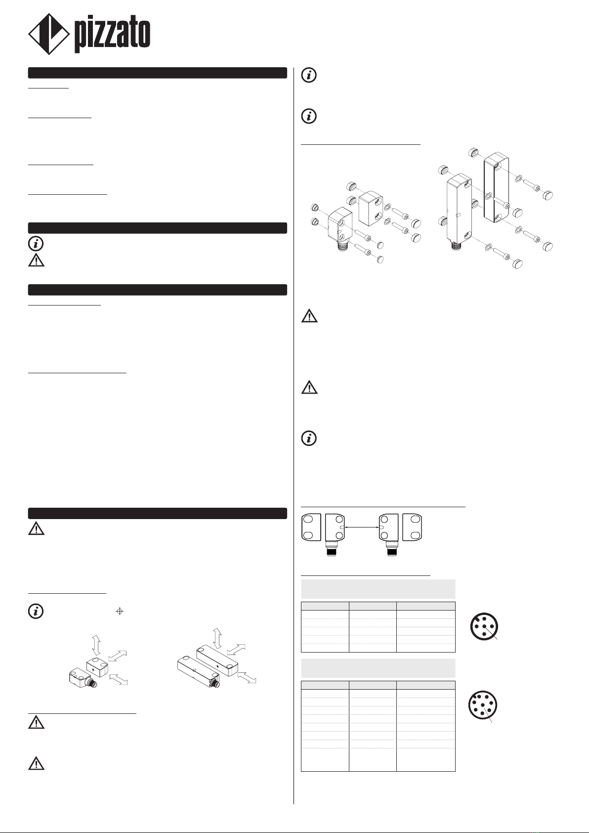
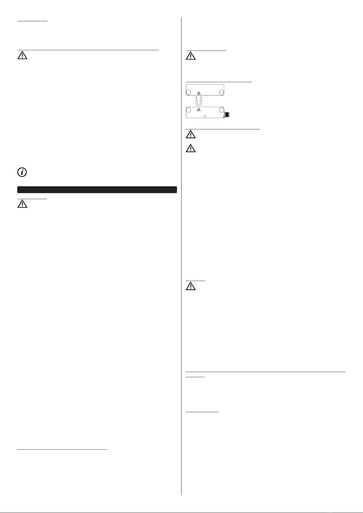
6.3.1 Versions with holding magnet
The devices with an internal magnet allow to generate a
holding force between the sensor and the actuator that can
keep the guard shut even if there are vibrations.
The magnetic holding force is available in various magnitudes
that can be chosen depending on the application (see
paragraph TECHNICAL DATA).
6.4 Maintenance and functional tests
Attention: Do not disassemble or try to repair the device. In case of any
malfunction or failure, replace the entire device.
Attention: In case of damages or wear it is necessary to change the whole
device including its actuator. Correct operation cannot be guaranteed when the device
is deformed or damaged.
- The installer is responsible for establishing the sequence of functional tests to which
the device is to be subjected before the machine is started up and during maintenance
intervals.
- The sequence of the functional tests can vary depending on the machine complexity
and circuit diagram, therefore the functional test sequence detailed below is to be
considered as minimal and not exhaustive.
- Perform the following sequence of checks before the machine is commissioned and
at least once a year (or after a prolonged shutdown):
1) Open the guard while the machine is moving. The machine must stop immediately.
The stopping time of the machine must be always shorter than the time required by the
operator for opening the guard and reaching the dangerous parts.
2) Try to start the machine while the guard is open. The machine must not start.
3) Check correct actuator to device alignment.
4) Check that no external parts are damaged. If damaged, replace the entire device.
5) The actuator must be securely locked to the door; make sure that none of the machine
operator’s tools can be used to disconnect the actuator from the door.
- The device has been created for applications in dangerous environments, therefore
it has a limited service life. Although still functioning, after 20 years from the date
of manufacture the device must be replaced completely. The date of manufacture is
placed next to the product code (see paragraph MARKINGS).
6.5 Wiring
Attention: Check that the supply voltage is correct before powering the device.
- Keep the charge within the values specified in the electrical operation categories.
- Only connect and disconnect the device when the power is off.
- Do not open the device for any reason.
- Discharge static electricity before handling the product by touching a metal mass
connected to earth. Any strong electrostatic discharge could damage the device.
- Power the safety switch and the other devices connected to it from a single SELV/
PELV source and in accordance with the applicable standards.
- Always connect the protection fuse (or equivalent device) in series with the power
supply for each device.
- During and after the installation do not pull the electrical cables connected to the
device.
- For devices with integrated cable, the free end of the cable (if it does not have a con-
nector) must be properly connected inside a protected housing. The cable must be
adequately protected from cuts, impacts, abrasion, etc.
6.6 Additional prescriptions for safety applications with operator protection
functions
Provided that all previous requirements for the devices are fulfilled, for installations
with operator protection function additional requirements must be observed.
- The utilization implies knowledge of and compliance with following stand-
ards: EN 60947-5-3, EN ISO 13849-1, EN 62061, EN 60204-1, EN ISO 14119,
EN ISO 12100.
6.7Limitsofuse- Use the device following the instructions, complying with its operation limits and the
standards in force.
- The devices have specific application limits (min. and max. ambient temperature,
mechanical endurance, IP protection degree, etc.) These limitations are met by the
device only if considered individually and not as combined with each other.
- The manufacturer’s liability is to be excluded in the following cases:
1) Use not conforming to the intended purpose;
2) Failure to adhere to these instructions or regulations in force;
3) Fitting operations not carried out by qualified and authorized personnel;
4) Omission of functional tests.
- For the cases listed below, before proceeding with the installation contact our techni-
cal assistance service (see paragraph SUPPORT):
a) In nuclear power stations, trains, airplanes, cars, incinerators, medical devices or
any application where the safety of two or more persons depend on the correct opera-
tion of the device;
b) cases not listed in these operating instructions.

10/30
7MARKINGSThe outside of the device is provided with external marking positioned in a visible
place. Marking includes:
- Producer trademark
- Product code
- Batch number and date of manufacture. Example: A20 ST1-123456. The batch's first
letter refers to the month of manufacture (A=January, B=February, etc.) The second
and third letters refer to the year of manufacture (20 = 2020, 21 = 2021, etc…)
8 TECHNICAL DATA
8.1 Housing
Housing made of glass fibre reinforced technopolymer, self-extinguishing.
Versions with integrated cable 5 x 0.25 mm2or 8 x 0.25 mm2, length 2 m, other lengths
on request.
Versions with M12 plastic or stainless steel connector.
Versions with 0.2 m cable length and integrated M12 connector, other lengths on
request.
Maximum length of connecting cables: 50 m.
(The cable length and section alter the deactivation impulses at the safety outputs. Check that the
capacity between the connecting cable's conductors is lower than that permitted in the electrical
data of the safety outputs)
Protection degree: IP67 acc. to EN 60529, IP69K acc. to ISO 20653
(Protect the cables from direct high-pressure and high-temperature jets)
Materials of versions with integrated M12 connector: PA66, PC, AISI304
Materials of versions with PVC cable: PA66, PC, NBR, PVC, AISI304
Materials of versions with PUR cable: PA66, PC, NBR, PUR, AISI304
Materials of versions with cable and M12 connector: PA66, PC, NBR, PVC, PUR,
AISI304, nickel-plated brass
8.2 General data
For safety applications up to: SIL 3 acc. to EN 62061
PL e, cat. 4 acc. to EN ISO 13849-1:2015
Interlock, no contact, coded: type 4 acc. to EN ISO 14119
Level of coding acc. to EN ISO 14119: high with SM •1T actuators
low with SM •0T actuators
Safety parameters:
MTTFD: 1551 years
PFHD: 1,19E-09
DC: High
Mission time: 20 years
Operating temperature for articles without cable:
ST•••••MP,ST•••••MK:-25°C…+70°C
ST•••••MK-T8:-35°C…+85°C
Operating temperature for articles with cable:
ST•••••N•,ST•••••M•:-25°C…+70°C, fixed installation
-15…+70°C flexible, mobile installation
ST•••••H•:-25°C…+70°C fixed, flexible, mobile
installation
ST•••••N•-T8,ST••••H•-T8,ST••••M•-T8:-35°C…+85°C, fixed installation
-15…+85°C flexible, mobile installation
Storage temperature: -35°C…+85°C
Vibration resistance: 10 gn (10...150 Hz) acc. to IEC 60068-2-6
Shock resistance: 30 gn; 11 ms acc. to EN 60068-2-27
Pollution degree 3
8.3 Power supply electrical data
8.3.1 Power supply electrical data
Rated operating voltage Ue: 24 Vdc SELV/PELV
10 ... 30 Vdc SELV/PELV(articlesSTH•••1••)Supply voltage tolerance: ± 15% of Ue (Only for 24 Vdc)
Operating current at Uevoltage:
minimum: 20 mA
with all outputs at maximum power: 550 mA
Rated insulation voltage Ui: 32 Vdc
Rated impulse withstand voltage Uimp: 1.5 kV
External protection fuse: 1 A type Gg or equivalent device
Overvoltage category: III
8.3.2 Electrical data of IS1/IS2/I3/EDM inputs
Rated operating voltage Ue1: 24 Vdc
10...30Vdc(articlesSTH•••1••)Rated current consumption: 2.5 mA
Switching time EDM state (tEDM): 500 ms
8.3.3 Electrical data of OS1/OS2 safety outputs
Rated operating voltage Ue2: 24 Vdc
10...30Vdc(articlesSTH•••1••)Output type: PNP type OSSD
Maximum current per output Ie2: 0.2 A
Minimum current per output Im2: 0.5 mA
Thermal current Ith2: 0.2 A
Utilization category: DC-13; Ue2=24 Vdc, Ie2=0.2 A
Short circuit detection: Yes
Overcurrent protection: Yes
Resettable internal protection fuse: 0.3 A
Duration of the deactivation impulses at the safety outputs: < 300 μs
Permissible capacitance between outputs: < 200 nF
Permissible capacitance between output and ground: < 200 nF
Response time (trI) after deactivation of inputs IS1 or IS2: < 15 ms
Response time (trA) after actuator removal: < 60 ms
Availability time: 2 s
8.3.4 Electrical data of O3 signalling output
Rated operating voltage Ue3: 24 Vdc
10...30Vdc(articlesSTH•••1••)Output type: PNP
Maximum current per output Ie3: 0.1 A (a)
Utilization category: DC-13; Ue3=24 Vdc, Ie3=0.1 A (a)
Short circuit detection: No
Overcurrent protection: Yes
Resettable internal protection fuse: 120 mA
(a)0,05AforarticlesST•••••••-T8withoperatingtemperatureT>70°C8.3.5 Actuation data
(A) (B)
Assured operating distance Sao: 8 mm 14 mm
Assured release distance Sar: 20 mm 26 mm
Rated operating distance Sn: 11 mm 18 mm
Rated release distance Snr: 13 mm 20.5 mm
(A)=withSMG•T,SMD•T,SML•T,SMH•Tactuators;(B)=withSME•TactuatorsRepeat accuracy: ≤10 % sn
Differential travel: ≤20 % sn
RFID transponder frequency: 125 kHz
Max. switching frequency: 1 Hz
Minimum distance between two sensors: 50 mm
Magneticholdingforceoftheactuator:25N(articlesSTHE•••••-H•TE)40N(articlesSTHE•••••-H•TF)50N(articlesSTHE•••••-H•TG)8.4 Compliance with standards
EN ISO 14119, IEC 61508-1, IEC 61508-2, IEC 61508-3, IEC 61508-4,
EN ISO 13849-1, EN ISO 13849-2, EN 62061, EN 60947-5-3, EN 60947-5-2,
EN 60947-1, EN 61326-1, EN 61326-3-1, EN 61326-3-2, EN IEC 63000,
ETSI EN 301 489-1, ETSI EN 301 489-3, ETSI 300 330-2, UL 508, CSA 22.2 No.14
8.5 Compliance with directives
Machinery Directive 2006/42/EC, EMC Directive 2014/30/EU, Radio Equipment
Directive 2014/53/EU, RoHS Directive 2011/65/EU, FCC Part 15
9SPECIALVERSIONSONREQUESTSpecial versions of the device are available on request.
The special versions may differ substantially from the indications in these operating
instructions.
The installer must ensure that he has received written information from the support
service regarding installation and use of the special version requested.
10 DISPOSAL
At the end of service life product must be disposed of properly, according to the
rules in force in the country in which the disposal takes place.
11 SUPPORT
The device has been created for safeguarding people’s physical safety, therefore in
case of any doubt concerning installation or operation methods, always contact our
technical support service:
Pizzato Elettrica Srl - Italy
Via Torino, 1 - 36063 Marostica (VI)
Telephone +39.0424.470.930
E-mail [email protected]
www.pizzato.com
Our support service provides assistance in Italian and English.
12 EC CONFORMITY DECLARATION
I, the undersigned, as a representative of the following manufacturer:
Pizzato Elettrica Srl - Via Torino, 1 - 36063 Marostica (VI) – ITALY
hereby declare that the product is in conformity with whatever prescribed by the 2006/42/
EC Machine Directive. The complete version of the present conformity declaration is
available on our website www.pizzato.com
Marco Pizzato
DISCLAIMER:
Subject to modifications without prior notice and errors excepted. The data given in this sheet are
accurately checked and refer to typical mass production values. The device descriptions and its
applications, the fields of application, the external control details, as well as information on installation
and operation, are provided to the best of our knowledge. This does not in any way mean that the
characteristics described may entail legal liabilities extending beyond the “General Terms of Sale”, as
stated in the Pizzato Elettrica general catalogue. Customers/users are not absolved from the obligation
to read and understand our information and recommendations and pertinent technical standards,
before using the products for their own purposes. Taking into account the great variety of applications
and possible connections of the device, the examples and diagrams given in the present manual are
to be considered as merely descriptive; the user is deemed responsible for checking that the specific
application of the device complies with current standards. This document is a translation of the original
instructions. In case of discrepancy between the present sheet and the original copy, the Italian version
shall prevail. All rights to the contents of this publication are reserved in accordance with current
legislation on the protection of intellectual property. The reproduction, publication, distribution and
modification, total or partial, of all or part of the original material contained therein (including, but not
limited to, texts, images, graphics), whether on paper or in electronic form, are expressly prohibited
without written permission from Pizzato Elettrica Srl.
All rights reserved. © 2021 Copyright Pizzato Elettrica
Other manuals for ST Series
1
This manual suits for next models
40
Table of contents
Other pizzato Accessories manuals
Popular Accessories manuals by other brands

CMC electronic
CMC electronic Esterline CMA-5024 installation manual

delight smart solutions
delight smart solutions 55376 User manual and installation guide

WMF
WMF Ambient Herbs home Single operating manual

Lexing
Lexing LX-MV-360S13A Instruction

MICRO-EPSILON
MICRO-EPSILON colorSENSOR LT-1-ST instruction manual

Autonics
Autonics BUP Series Installation