NKE STBD-PR User manual

http://www.nke-instrumentation.com Tel 02-97-36-41-31 Fax 02-97-36-55-17
PAGE 1/18
USER MANUAL
STBD-PR
Rev 5
Document reference : STBD-33-30-065_UTI_UK.doc
Document applicable to product(s) : STBD-PR station and profileur

http://www.nke-instrumentation.com Tel 02-97-36-41-31 Fax 02-97-36-55-17
PAGE 2/18
SOMMAIRE
1. INTRODUCTION ..........................................................................................................................................................3
2. PHOTO............................................................................................................................................................................4
3. CHARACTERISTICS ...................................................................................................................................................5
3.1 DATA LOGGER CHARACTERISTICS .............................................................................................................................5
3.2 CHARACTERISTICS OF THE MEASUREMENT................................................................................................................5
3.2.1 Turbidity channel..............................................................................................................................................5
3.2.2 Selection of Turbidity measurement range .......................................................................................................5
3.2.3 Temperature channel........................................................................................................................................6
3.2.4 Pressure or depth channel ................................................................................................................................6
4. IMPLEMENTATION....................................................................................................................................................7
4.1 RADIO STBD-PR TIME SETTING................................................................................................................................8
4.2 PRESENTATION OF THE CONCENTRATOR: ............................................................................................................8
5. ADJUSTMENT & MAINTENANCE PROCEDURES...............................................................................................9
5.1 PRESSURE SENSOR.....................................................................................................................................................9
5.2 DEPTH ZERO DRIFT CORRECTION ...............................................................................................................................9
5.3 ADJUSTMENT TEMPERATURE ..................................................................................................................................10
5.4 TURBIDITY SENSOR..................................................................................................................................................11
5.4.1 Adjustment ......................................................................................................................................................11
6. TECHNICAL CHACTERISTICS..............................................................................................................................13
6.1 MECHANICAL CHARACTERISTICS.............................................................................................................................13
6.2 SPECIFICATIONS OF RADIO TRANSMISSION..............................................................................................................13
6.3 MEMORY AUTONOMY...............................................................................................................................................13
6.3.1 STBD-PR in recording mode at 3 seconds (Production of a profile)..............................................................13
6.3.2 STBD-PR in recording mode at 1 minute (Short term monitoring) ................................................................13
6.3.3 STBD-PR in recording mode at 10 minutes (Long term monitoring) .............................................................13
6.4 ENERGY AUTONOMY................................................................................................................................................14
6.4.1 as data-logger.................................................................................................................................................14
6.4.2 used with RECOPESCA..................................................................................................................................15
6.4.3 Estimate by the Winmemo II software.............................................................................................................15
7. OPTIONNAL USE OF AN AUTONOMOUS BRUSH.............................................................................................16
7.1 SPECIFICATIONS.......................................................................................................................................................17
7.1.1 Assembly .........................................................................................................................................................17
8. INSTALLATION OF RUBBER PROTECTIONS....................................................................................................18
8.1 STBD-PR POSITIONING FOR RADIO OPERATION ......................................................................................................18
9. MECHANICAL LAYOUT..........................................................................................................................................18
10. END OF LIFE...........................................................................................................................................................18
http://www.nke-instrumentation.com Tel 02-97-36-41-31 Fax 02-97-36-55-17
PAGE 3/18
1. INTRODUCTION
The STBD-PR probe allows the measurement and recording of pressure, temperature and turbidity (or
concentration of suspended particles). The probe is optimized for profile measurements and its Turbidity
channel has an automatic range selection.
This probe consists of a Seapoint sensor that emits light modulated at 880 nm. The light reflected by particles
(backscatter) is detected by a cell that provides a signal proportional to the concentration of suspended particles
in the medium to be measured.
The setup and reading are carried out without opening the housing, using an Inductive or Radio Data Pencil
connected to the USB port of a PC computer.
All the command functions are available in the Winmemo II software provided with the Data Pencil Kit.
Used with RECOPESCA (automated data acquisition network on-board ships), the STBD-PR automatically
transmits its data to a CONCENTRATOR via a radio link.
Applications:
Suspended biomass, visibility, pollution, sediment transport, particle profile.
Equipment required for the use of an STBD-PR:
-1 Data Pencil, reading interface at 57,600 bauds
-1 PC computer.
-The Winmemo II software.
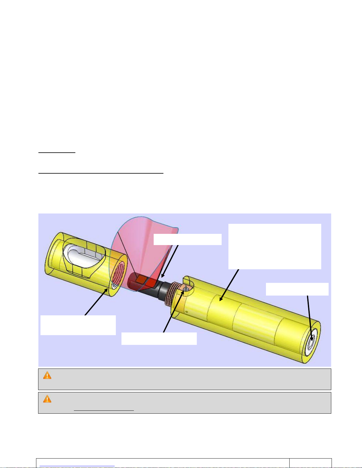
The turbidity sensor is protected by a cover that is screwed onto the body of the STBD-PR. A thread start
located on the protective cover and the body of the STBD-PR allows this protective cover to be correctly
oriented so as to avoid distorting the turbidity measurement.
A rubber protection can be added as an option to protect the entire probe.
If the protective cover of the turbidity sensor breaks, the STBD-PR must be returned to the factory to
replace the cover + sensor bracket assembly, WHICH MUST BE PAIRED.
To ensure the good operation of the STBD-PR, a gap of 11cm must be left in front of the field of view of
the turbidity sensor.
Pressure sensor
Turbidity sensor
Temperature sensor
Holding screws of the
protective cover
Position of the radio
transmission/reception antenna.
This side of the STBD-PR must be
free of any metal obstruction to
ensure good radio communication.

http://www.nke-instrumentation.com Tel 02-97-36-41-31 Fax 02-97-36-55-17
PAGE 4/18
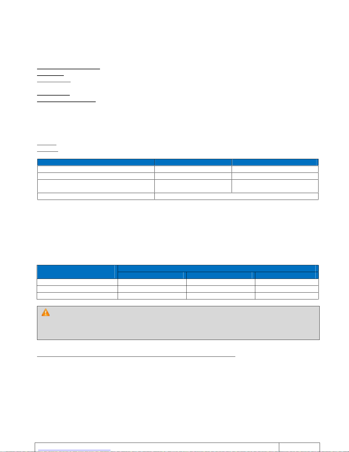
2. PHOTO
Turbidity sensor Seapoint
Temperature sensor
Pressure sensor
Protective cover
Shoulders for attaching
http://www.nke-instrumentation.com Tel 02-97-36-41-31 Fax 02-97-36-55-17
PAGE 5/18
3. CHARACTERISTICS
3.1 DATA LOGGER CHARACTERISTICS
Measurement frequency: Programmable from 1s to 99hrs
Clock drift: 1min / month
Memory size: 1Mb with data compression.
PC interface: Radio transmission
Operating temperature: -5°C / +35°C
3.2 CHARACTERISTICS OF THE MEASUREMENT
3.2.1 Turbidity channel
Sensor: Seapoint STM probe
Ranges: 25 NTU, 125 NTU or 750 NTU: choice between manual and automatic range.
Turbidity range (NTU)
Linearity
Resolution (NTU)
0 – 25
< 5%
< 0.007
0 – 125
< 5%
< 0.035
0 – 750
(Non linear from 750 to 2000)
< 5%
(0 to 750 NTU)
< 0.5
(0 to 750 NTU)
Automatic
As per range
3.2.2 Selection of Turbidity measurement range
The measurement range of the Turbidity channel may be forced by the user (choice between the 3 ranges) or
configured in "automatic" mode.
In "automatic" mode, the probe selects the best range to maximize the accuracy of measurement. The algorithm
that allows automatic range selection carries out 1 to 3 measurements to determine the optimum range.
The duration of each measurement, with no range change, is 1s.
The duration of each measurement, with 1 or 2 range changes, is shown in the table below.
Turbidity value to be
measured
Previous turbidity range
0 – 25 NTU
0 – 125 NTU
0 – 750 NTU
MEAS < 22 NTU
1s
2s
2s
22 NTU < MEAS < 110 NTU
2s
1s
2s
MEAS > 750 NTU
3s
2s
1s
Range selection is done by configuring channel 2 according to the table below:
A range change may result in a start of block (This corresponds to a On/Off) being created in the
measurement file. This start of block implies a new dating for the measurements. This is achieved when the
programmed measurement frequency is less than the time required for processing. New dating of the
measurements takes place when the programmed frequency is 1 or 2 seconds and there has been a range
change in the measurement cycle.

http://www.nke-instrumentation.com Tel 02-97-36-41-31 Fax 02-97-36-55-17
PAGE 6/18
For the choice of turbidity measurement range, the Winmemo II software must be configured in EXPERT
mode.
3.2.3 Temperature channel
Sensor: Thermistor
Measurement range: -5°C / +35°C
Maximum resolution: 11m°C at 0°C, 13m°C at 10°C, 20m°C at 20°C
Accuracy: 50m°C in the range 0°C/20°C
Reponse time STBD-PR : < 0.5s at 63%
Reponse time STBD-PR : < 2s at 63%
3.2.4 Pressure or depth channel
Pressure sensor Piezoresistive with 0.2% accuracy and resolution below 0.02%or
Type of product:
Depth range
Accuracy
Max. resolution
STBD300-PR
0 – 300m
0.6 m
9 cm
STBD1200-PR
0 – 1200m
2.4 m
0.35 m
Canal
Gamme de
turbidité
2
0 – 25 NTU
3
0 – 125 NTU
4
0 – 750 NTU
5
Automatique
http://www.nke-instrumentation.com Tel 02-97-36-41-31 Fax 02-97-36-55-17
PAGE 7/18
4. IMPLEMENTATION
The parameter setting and reading of the STBD-PR data logger are performed without opening the housing
using the Data Pencil connected to the USB link of a PC computer.
All the control functions are available in the Winmemo II software.
Note: communication with the Radio STBD-PR can only take place above water.
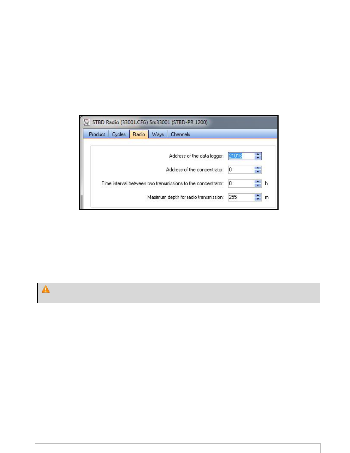
When editing the configuration with the Winmemo II software, a “Radio” button allows to edit the parameters
specific to radio communication. They are accessible only if the Winmemo II software is configured in EXPERT
mode.
-Address of the data logger: Parameter that specifies the radio address of the data logger, (unique factory-
defined address for each product). The Radio Data Pencil uses this address to communicate with the
STBD-PR data logger.
-Address of the Concentrator: Parameter that specifies the radio address of a Concentrator with which the
STBD-PR can automatically communicate.
-Time interval between two transmissions to the Concentrator: Parameter that specifies the rate of
transmission of the STBD-PR measurements to the Concentrator.
-Minimum depth for radio transmission: Radio communication does not work when the STBD-PR is
immersed. This Parameter specifies the immersion depth beyond which the STBD-PR no longer attempts to
communicate with the Concentrator.
The Concentrator's Address and the Time Interval between two transmissions to the
concentrator must be set at 0 in case the STBD-PR does not communicate with the Concentrator.

http://www.nke-instrumentation.com Tel 02-97-36-41-31 Fax 02-97-36-55-17
PAGE 8/18
4.1 RADIO STBD-PR TIME SETTING
All the data loggers assigned to a Concentrator date their measurements based on one single reference: the
Concentrator.
For that, the Concentrator is synchronised with Universal Time UT thanks to its GPS.
The STBD-PR automatically synchronises itself with the time of the Concentrator at each transfer of
measurements.
4.2 PRESENTATION OF THE CONCENTRATOR:
Designed to be installed on board a boat, it receives the measurement files transmitted by data loggers such as
the STBD-PR via the radio connection.
It also enables the logging of GPS positions (Geodetic positions).
The data collected are temporarily stored in the Concentrator’s memory, before they are transmitted by GPRS
modem, via an email, to the processing station.
In order to avoid time lag with the first measurements (i.e. before the first transmission with the
Concentrator), time setting of the STBD-PR using the Winmemo II software must be done by first setting the
clock of the PC at universal time UT.

http://www.nke-instrumentation.com Tel 02-97-36-41-31 Fax 02-97-36-55-17
PAGE 9/18
5. ADJUSTMENT & MAINTENANCE PROCEDURES
In order to set the probe, the Winmemo II software must be configured in EXPERT mode ("Tools" tab in
Winmemo II).
5.1 PRESSURE SENSOR
The piezoresistive pressure sensor used on the SAMBAT requires no particular maintenance.
Simply follow these guidelines to preserve its service life:
- Maintain a sufficient amount of silicone grease in the pressure sensor port. To do so, put a "dab" of
silicone grease on your finger and fill the orifice.
- Never insert any objects in the pressure sensor port!
5.2 DEPTH ZERO DRIFT CORRECTION
In case of zero drift channel 0 (depth or pressure) it is possible to correct the adjustment details:
- Login to probe Winmemo II and switch to "Expert" mode.
- Make a "reading real time" and meet the physical value (P2) depth measured by SAMBAT at atmospheric
pressure.
- Make a "Play Panel" and select Channel 0 in the "channels" configuration tab.
- Raise the calibration coordinates example:
-Vcan0 point(s) of the converter correspond to the physical value P0.
-Vcan1 point(s) of the converter correspond to the physical value P1.
- Replace:
-P0 by the value of (P0 – P2)
-P1 by the value of (P1 – P2)
- - Save these values in SAMBAT with "total Initialize" function, and check with "Real-time reading" function
that the displayed depth at atmospheric pressure is 0.
The pressure or depth channel is compensated by a value of atmospheric pressure.
The aim is for every probe to be able to measure the same pressure (or depth) despite being set to a
different atmospheric pressure.
In order to achieve this, the physical values of adjustments are reduced to the reference atmospheric
pressure of 1013 hPa (or 1013 mbar) during calibration.
To know the absolute depth (which takes into account atmospheric pressure), the difference between
the actual atmospheric pressure and the reference value (1013 hPa) must be calculated.
The result must therefore be added to or subtracted from the depth values measured

http://www.nke-instrumentation.com Tel 02-97-36-41-31 Fax 02-97-36-55-17
PAGE 10/18
5.3 ADJUSTMENT TEMPERATURE
- Select maximum resolution, i.e. 12 bits, for the temperature channel (Way 0 – Channel 0).
- Set the probe in recording mode at a 1 second frequency and successively immerse it for 10 minutes in
2 baths with different temperatures:
- One bath at low temperature (+5°C).
- One bath at high temperature (+25°C).
- During these recordings measure the temperature using a reference thermometer:
- Note TX low temperature of the bath,
- Note TY high temperature of the bath.
- The temperature of the bath must be constant throughout the recording (thermostatic bath
recommended).
- Read the STBD once again and save the measurements to a file.
- Display the temperature curve and record the raw value measured for each bath. This is the value in
brackets that follows the Channel’s indication. Example: V0(X).
-XCAN (pts) value read at low temperature.
-YCAN (pts) value read at high temperature.
Edit the Calibration parameters of Channel 0 and modify as follows:
-Xpoint(s) of the converter correspond to the physical value TX.
-Ypoint(s) of the converter correspond to the physical value TY.
Display the temperature curve once more, and check the temperatures of the different baths.
Edit the setting parameters of Channel 0 and transfer the new Calibration coordinates (X,TX,Yand TY) to
the SP2T using the button "Total initalization".
http://www.nke-instrumentation.com Tel 02-97-36-41-31 Fax 02-97-36-55-17
PAGE 11/18
Any degradation of the optical windows (scratching, punching) will irreversibly damage the sensor.
5.4 TURBIDITY SENSOR
Seapoint turbidity sensor
After every use, thoroughly rinse the sensor with clear water.
If deposits such as biofilm or mud remain, clean the sensor with soapy water and wipe the head with a soft cloth
or a paper towel.
5.4.1 Adjustment
The adjustment of the turbidity sensor is performed in a black container using standard Formazine solutions.
It must be done under fluorescent or LED lighting.
Incandescent lamps emit large amounts of energy at the same wavelength that the sensor operates at, which
may interfere with the measurements
- The principle is identical to the adjustment in (§ 5.3).
The STBD-PR probe has 3 measurement ranges. Each of these ranges is linked to a measurement channel, as
described in the table below:
Turbidity range
Channel
0 – 25 NTU
2
0 – 125 NTU
3
0 – 750 NTU
4
Automatic
5
Select the maximum resolution, i.e. 12 bits, for the turbidity channel (Channel 2).
Prepare two baths of upper and lower calibration for each range.
(Example: Preparation of 2 baths of 5 and 20 NTU for the range 0 to 25NTU = channel 2)
Select the maximum resolution, i.e. 12 bits, for the turbidity channel (Channel 2).
High turbidity bath
Immerse the STBD-PR probe in a high turbidity medium.
Once the medium has become stable (homogenization of suspended particles), place the STBD-PR in
recording mode at a frequency of 3 seconds for 5 minutes.
Note the high turbidity reference value TX.
Low turbidity bath
Immerse the STBD-PR probe in a low turbidity medium.
Once the medium has become stable (homogenization of suspended particles), place the STBD-PR in
recording mode at a frequency of 3 seconds for 5 minutes.
Note the low turbidity reference value TY.
Read the STBD-PR once again and create a measurement file.
Display the Turbidity curve and record the raw value measured for each bath. This is the value in brackets
that follows the indication of Channel 2 (raw value).
-X raw value of the high turbidity bath
-Y raw value of the low turbidity bath
Optical windows

http://www.nke-instrumentation.com Tel 02-97-36-41-31 Fax 02-97-36-55-17
PAGE 12/18
Edit the setting parameters for the channel to be adjusted (e.g. channel 4 for the range 0 to 750 NTU) and
modify as follows :
-Xpoint(s) of the converter correspond to the physical value TX.
-Ypoint(s) of the converter correspond to the physical value TY.
Display the file to check the turbidity values of the different baths.
Edit the setting parameters of the channel in use and transfer the new coordinates (X,TX ,Yand TY) to the
data-logger using the button "Total Initialization".
Perform the setting operations identically for every other range.

http://www.nke-instrumentation.com Tel 02-97-36-41-31 Fax 02-97-36-55-17
PAGE 13/18
6. TECHNICAL CHACTERISTICS
6.1 MECHANICAL CHARACTERISTICS
Dimensions: Length = 290mm,Housing diameter = 40mm
Weight in air:445 grams (with no rubber protection)
Materials:
-STBD300: Sensor body and cap made of "Ertalyte", protective cover made of "POM"
-STBD1200: Sensor body and cap made of "Ketron", protective cover made of "POM",.
Data logger type
Maximum immersion
without recalibration
without electrical failure
without mechanical
failure
STBD300-PR
500 m
500 m
500 m
STBD1200-PR
2000 m
2000 m
2000 m
Optional: STBD can be supplied with a flexible protective case that improves their resistance to shocks.
6.2 SPECIFICATIONS OF RADIO TRANSMISSION
Frequency: 868.3 MHz
Transmission power: 5mW
Range in free field: 25m
6.3 MEMORY AUTONOMY
The memory autonomy indicated thereafter is provided for the operating mode “Manual start and stop”
with an interval between each measurement estimated at 8 points of the resolution.
6.3.1 STBD-PR in recording mode at 3 seconds (Production of a profile)
For an STBD-PR performing measurements at a frequency of 3 seconds, the memory autonomy will be
approximately 5 days.
6.3.2 STBD-PR in recording mode at 1 minute (Short term monitoring)
For an STBD-PR performing measurements at a frequency of 1 minute, the memory autonomy will exceed 3
months.
6.3.3 STBD-PR in recording mode at 10 minutes (Long term monitoring)
For an STBD-PR performing measurements at a frequency of 10 minutes, the memory autonomy will be
approximately 3 years.
The radio antenna is positioned on the side of the CTN bracket and fields of view of the Turbidity sensor
For maximum radio range, the side of the STBD-PR that comprises the CTN bracket and fields of view of
the Turbidity sensor must be free of any metal obstruction.

http://www.nke-instrumentation.com Tel 02-97-36-41-31 Fax 02-97-36-55-17
PAGE 14/18
6.4 ENERGY AUTONOMY
6.4.1 as data-logger
In this mode, the probe is constantly recording at the specified measurement frequency. The energy
consumption varies according to the configuration settings. The battery service life is a function of the following
parameters (in order of significance):
1. Measurement frequency (or average of the various frequencies used)
2. Start/stop mode used (e.g.: A mode that uses a start or stop on condition uses more energy than the
standard “manual start and stop” mode because 1 additional measurement is taken to check the
condition)
3. Use of the “read channels” mode which allows real-time reading
4. Radio connection to the probe
Measurement frequency between 1s and 30s
Measurement frequency between 1s and 1800s (30min)

http://www.nke-instrumentation.com Tel 02-97-36-41-31 Fax 02-97-36-55-17
PAGE 15/18
6.4.2 used with RECOPESCA
For an STBD-PR that performs measurements using the following cycle, the energy autonomy will be
approximately 9 months:
-6 hauls per day
-For each haul, measures for 10 minutes at a frequency of 1 second (descending phase) and the measures
for 3 hours at a frequency of 10 minutes.
-2 radio transmissions (to the concentrator) per day.
6.4.3 Estimate by the Winmemo II software
To help you determine the energy capacity and remaining life time, the Winmemo II software provides an
estimate of this information based on the average working mode of the STBD-PR (average measurement
frequency, period of usage, use of the “read” mode). This estimate (through learning) is automatically reset after
every battery replacement.
This estimate can be accessed from the “Status” tab when the module is stopped.
The estimate of the remaining life time will be all the more reliable if the next operating mode is close to
the STBD-PR’s average operating mode (for example, when the measurement frequency is not modified).
http://www.nke-instrumentation.com Tel 02-97-36-41-31 Fax 02-97-36-55-17
PAGE 16/18
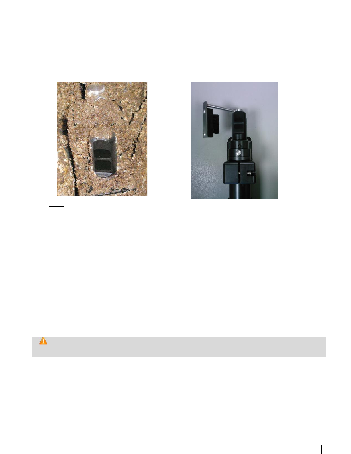
7. OPTIONNAL USE OF AN AUTONOMOUS BRUSH
For areas high turbidity (silt, mud, algae, etc…), it may be necessary to use a mechanical system designed to
clean the field of view of the turbidity sensor.
In this case, it is possible to use a mechanical wiper system designed to accommodate the offset turbidity
sensor. This system wipes the sensor's field of view at regular intervals and thus prevents measurements from
being lost due to the fouling of the sensor.
The STBD sensor is installed in the flange located at the front of the wiper so that the flat side of the field of view
is directly facing the wiper, and that the latter covers the field of view while it moves.
The brush must be slightly pressed against the surface of the field of view. If the brush is pressed with
excessive force, the lifespan of the batteries will be reduced and the turbidity probe's field of view is likely to be
damaged.
If the brush is pressed with insufficient force, it will not clean effectively.
Brush pressure can be adjusted by removing the nut at the end of the wiper arm, and by turning the latter in the
desired direction. The locknut must be tightened after adjustment.
The housing that contains the electronics and batteries must be mounted using its stainless steel mounting
bracket.
Avoid attaching this support directly onto a metal structure that is not made from marine grade stainless steel
(STAINLESS STEEL A4 or 316), as this may subject the metal to electrolysis and deterioration. Marine bolts
made from the same grade of stainless steel must be used for mounting.
Once the wiper control housing and the wiper housing are mounted, attach the cable using cable clips to
prevent possible snags and clogging with debris. The cable must be clamped so as not to move constantly with
the currents and thus wear prematurely.
The measurement of turbidity of the probe is independent and asynchronous with the sweep. This
can thus cause an incorrect measurement during the passage of the broom on the sensor,

http://www.nke-instrumentation.com Tel 02-97-36-41-31 Fax 02-97-36-55-17
PAGE 17/18
7.1 SPECIFICATIONS
Reference: "Hydro-Wiper A" from ZEBRA-TECH
Wiping interval:15, 30, 45, 60, 120, 180, 240, 300, 360 or 720 minutes
Wiping time lag: +/- 1 minute per year (0 – 40°C)
Power supply: 6 AA alkaline batteries (DURACELL MN1500 battery or equivalent)
Depth limit: 30 m (optional 100 m)
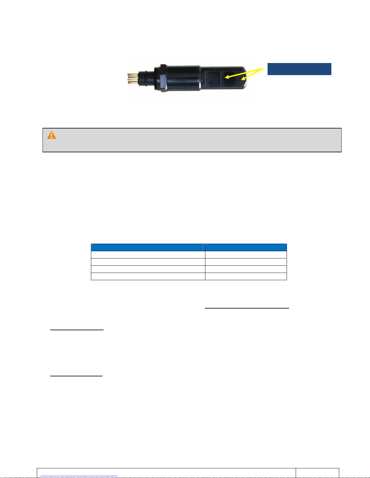
7.1.1 Assembly
Remove the protective cap from turbidity sensor
-Unscrew the two screws HC
-Remove the protective cover
Insert the STBD probe in the flange
-Remove the screw of the STBD probe
-Insert the Turbidity sensor first
-Focus the probe so that the temperature sensor passes
in the open window
-Position the sensor so that the brush covers the optical window
for moving.
-Secure the sensor by tightening the fixing screw.
-Adjust the pressure of the brush to playing on the length of the
arm
For more information, please refer to the user guide from ZEBRA-TECH
Sens de montage
http://www.nke-instrumentation.com Tel 02-97-36-41-31 Fax 02-97-36-55-17
PAGE 18/18
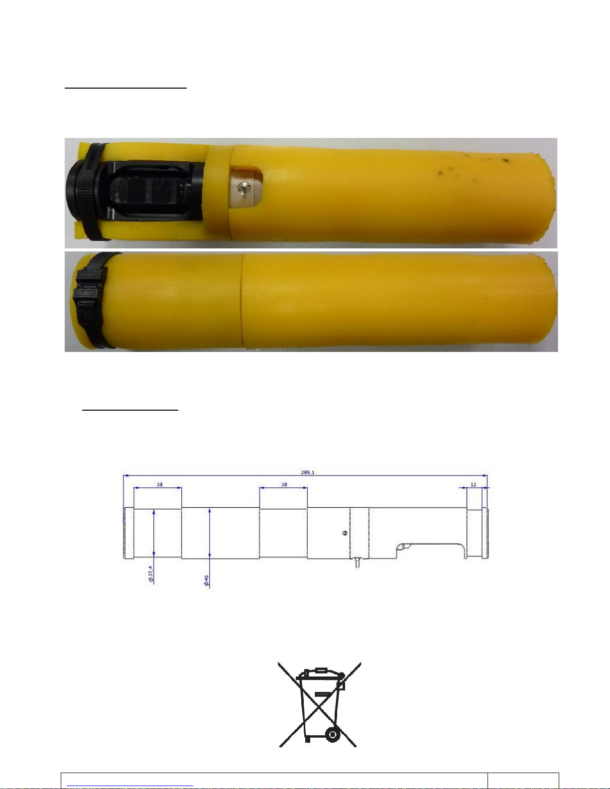
8. INSTALLATION OF RUBBER PROTECTIONS
As per the following photos:
- Slide and mount all the protections.
- Maintain the rubber protection of the Turbidity sensor using a BLACK Colson-type collar so as to avoid any
offset on the turbidity measurement.
8.1 STBD-PR POSITIONING FOR RADIO OPERATION
The radio antenna is positioned on the side of the CTN bracket and fields of view of the Turbidity sensor.
For maximum radio range, the STBD-PR must be free of any mechanical obstruction over its entire length, on
the side of the CTN sensor and fields of view of the Turbidity sensor.
9. MECHANICAL LAYOUT
10. END OF LIFE
The STBD-PR is an electronic equipment.
According to the Directive Waste of Electric and electronic Equipments (WEEE), this equipment must be
collected by an organism approved for the selective collection of the WEEE.
Table of contents
Other NKE Transmitter manuals

Popular Transmitter manuals by other brands

IMG STAGE LINE
IMG STAGE LINE TXS-871HSE instruction manual

JUMO
JUMO dTRANS T02 Ex operating instructions

Sartorius
Sartorius GWT MP 25 operating instructions

Vega
Vega VEGABAR 87 operating instructions

Burkert
Burkert 8022 Series operating instructions

KLAY-INSTRUMENTS
KLAY-INSTRUMENTS 8000 Series Safety manual

Endress+Hauser
Endress+Hauser Liquisys M COM 223 operating instructions

FlowLine
FlowLine FloaTek LV55 Series manual

Sony
Sony TMR-BT10A operating instructions

Lightware
Lightware HDMI-TP-TX50 quick start guide

Invonics
Invonics EN1501-EXT installation instructions

Becker
Becker CentronicPLUS SWC548 PLUS Assembly and operating instructions


