2.4.20 357-06289-01 Rev A © Inovonics, 2019 - www.inovonics.com 2
• The pulse width of a switch output when it is activated must be greater
than or equal to 10ms.
• A maximum rate of six pulses per second.
• Closed impedance of the pulser mechanism must be smaller than 1k
ohm.
• Open impedance of the pulser mechanism must be greater than five
megohms.
The count totalizer corresponds to the number of totalizer input pulses. The
counts accumulate until the number 9,999,999 is reached. The totalizer will
then go to zero on the next count.
4 Register the Transmitter
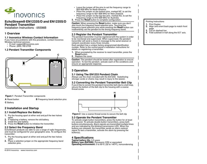
To register the EN1501-EXT
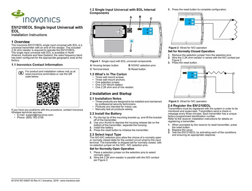
1. Confirm that transmitter is connected to the meter.
2. Confirm that the battery is installed.
3. Press the reset button to take the transmitter out of sleep/shipping
mode.
• The LED on the board will blink, indicating the transmitter has woken
up.
4. See the TapWatch Application User Manual for details about adding
transmitters to a site.
5 Compliance Requirements
5.1 FCC Requirements for the EN1501-EXT
The EN1501-EXT has received a Modular Grant to FCC/IC regulations.
The integrator is responsible to test the final installation to verify
compliance to FCC/IC regulation for unintentional emissions.
The integrator is responsible for properly labeling the product containing
the EN1501-EXT. Labels must be placed on the outside of the product, and
must include a statement indicating that the product contains the EN1501-
EXT, along with the FCC and IC number.
Example 1 “Contains EN1501-EXT Pulse Counting Transmitter
FCC ID: HCQ3B6T; IC ID: 2309A - T
Example 2 “Contains FCC ID: HCQ3B6T; IC ID: 2309A - OTPMTX
5.2 Television and Radio Interference
This equipment has been tested and found to comply with the limits for a
Class B digital device, pursuant to Part 15 of the FCC Rules. These limits
are designed to provide reasonable protection against harmful interference
in a residential installation. This equipment generates, uses and can
radiate radio frequency energy and, if not installed and used in accordance
with the instructions, may cause harmful interference to radio
communications. However, there is no guarantee that interference will not
occur in a particular installation. If this equipment does cause harmful
interference to radio or television reception, which can be determined by
turning the equipment off and on, the user is encouraged to try to correct
the interference by one or more of the following measures:
• Reorient or relocate the receiving antenna.
• Increase the separation between the equipment and receiver.
• Connect the equipment into an outlet on a circuit different from that to
which the receiver is connected.
• Consult the dealer or an experienced radio/TV technician for help.
5.3 FCC Part 15 and Innovation, Science and Economic
Development Canada (ISED) Compliance
This device complies with part 15 of the FCC Rules, and ISED license-
exempt RSS standard(s). Operation is subject to the following two
conditions: (1) this device may not cause interference, and (2) this device
must accept any interference that may cause undesired operation of the
device.
Le présent appareil est conforme aux CNR Innovation, Sciences et
Développement économique Canada applicables aux appareils radio
exempts de licence. L'exploitation est autorisée aux deux conditions
suivantes: (1) l'appareil ne doit pas produire de brouillage, et (2) l'utilisateur
de l'appareil doit accepter tout brouillage radioélectrique subi, même si le
brouillage est susceptible d'en compromettre le fonctionnement.
5.4 Radiation Exposure Limits
FCC
This equipment complies with FCC radiation exposure limits set forth for an
uncontrolled environment. In order to avoid the possibility of exceeding the
FCC radio frequency exposure limits, human proximity to the antenna shall
not be less than 20 cm during normal operation and must not be co-located
or operating in conjunction with any other antenna or transmitter.
ISED
This equipment complies with ISED RSS-102 radiation exposure limits set
forth for an uncontrolled environment. This transmitter must be installed to
provide a separation distance of at least 20 cm from all persons and must
not be co-located or operating in conjunction with any other antenna or
transmitter.
Cet équipement est conforme avec ISED RSS-102 des limites d'exposition
aux rayonnements définies pour un environnement non contrôlé. Cet
émetteur doit être installé à au moins 20 cm de toute personne et ne doit
pas être colocalisé ou fonctionner en association avec une autre antenne
ou émetteur.
Note: Inovonics supports recycling and reuse whenever possible. Please
recycle these parts using a certified electronics recycler.


