<11 >
FIGURES
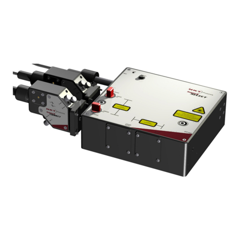
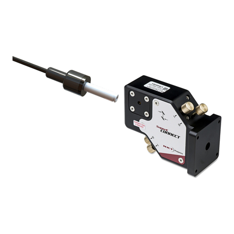
Figure 1: SuperK SELECT with dual AOTF outputs – general view ........................................... 15
Figure 2: SuperK SELECT standard dual RF driver system view............................................... 17
Figure 3: Optical output shutters – VIR/NIR set open and NIR/IR set closed ............................ 18
Figure 4: Top panel..................................................................................................................... 19
Figure 5: Optical Interfaces......................................................................................................... 21
Figure 6: Optical Interfaces......................................................................................................... 22
Figure 7: Electrical Interfaces ad optical input ............................................................................ 23
Figure 8: External RF Driver unit – general view ........................................................................ 24
Figure 9: External RF Driver – rear panel ................................................................................... 25
Figure 10: SELECT Status LEDs................................................................................................ 27
Figure 11: Side panel manufacturing label ................................................................................. 28
Figure 12: Top panel labels ........................................................................................................ 29
Figure 13: Partially inserting the collimator ................................................................................. 32
Figure 14: Collimator alignment key and slot.............................................................................. 32
Figure 15: Collimator lock screw ................................................................................................ 33
Figure 16: Connecting a SELECT - single ERD ......................................................................... 34
Figure 17: Connecting single ERDs............................................................................................ 34
Figure 18: Bus defeater .............................................................................................................. 34
Figure 19: Setting External bus addresses - single ERD system ............................................... 35
Figure 20: Connecting a SELECT - dual ERD ............................................................................ 36
Figure 21: Connecting dual ERDs .............................................................................................. 36
Figure 22: Setting External bus addresses - dual ERD system .................................................. 37
Figure 23: Spectral output of a single AOTF channel ................................................................. 39
Figure 24: AOTF transmission spectrum for varying RF powers ................................................ 40
Figure 25: Optical power for a specific wavelength as a function of RF power .......................... 41
Figure 26: Wavelength versus optimum RF power level ............................................................ 41
Figure 27: CONTROL panel navigation ...................................................................................... 43
Figure 28: Device selector icon................................................................................................... 44
Figure 29: Device selector .......................................................................................................... 44
Figure 30: Device selector set to 0xE bus address..................................................................... 44
Figure 31: Status Panel .............................................................................................................. 45
Figure 32: CONTROL settings.................................................................................................... 47
Figure 33: Setup menu page ......................................................................................................47
Figure 34: CONTROL settings.................................................................................................... 49


