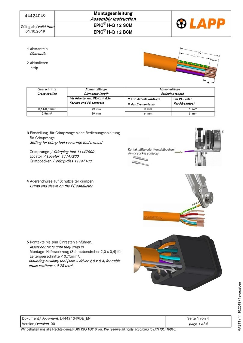
NKT CB 36-630 User manual

nkt cables GmbH
Kabelgarnituren
Cable accessories
Helgoländer Damm 75
D- 26954 Nordenham
www.nktcables.de
Telefon: +49 (0) 4731/364-330
Telefax: +49 (0) 4731/364-368
Anleitung / Instructions: 26 242 42
Ausgabe / Edition: 25.09.2012
CB 36-630
Abzweig-Kabelsteckteil für kunststoffisolierte Kabel,
Anschlusstyp C, max. Systemspannung bis 42 kV,
Dauernennstrom 630 A.
Branch connector for plastic-insulated cables,
connecting type C, max. system voltage up to 42 kV,
continous nominal current 630 A.
190
110
245
d
Ø~84
max.
CB 36-630
Größe
Size
Bestell-Nr.
Ref.No.
für Kabel
for cables mm² Ø Aderisolierung (d)
Ø core insulation (d)
incl. Press-
kabelschuh
incl. crimp
cable lug
Al
incl. Press-
kabelschuh
incl. crimp
cable lug
Cu
Basissatz
Basic set
18/30(36) kV
25 5003
17,0 - 24,3
26 331 51 26 331 01 26 331 91
35 26 331 52 26 331 02
50
5005
21,2 - 33,6
26 331 53 26 331 03
26 331 92
70 26 331 54 26 331 04
95 26 331 55 26 331 05
120 26 331 56 26 331 06
150
5027
28,9 - 40,0
26 331 57 26 331 07
185 26 331 58 26 331 08
26 331 93240 26 331 59 26 331 09
300 26 331 60 26 331 10
Ø~79
M12

2
Attention: Installation is only allowed by
medium-voltage electrician and according to
these assembly instructions.
Follow operating instructions of your tools
and devices! Before beginning control the components
for quality and quantity. Observe safety regulations.
These assembly instructions are designed for Cu wire
screened XLPE cables with solid extruded outer conduc-
tive layer only. For other cable types, please contact us
for pertinent instructions and or materials. Please note
possible additional sheets.
Achtung: Dieses Produkt darf nur von ausge-
bildetem Starkstrompersonal gemäß dieser
Montageanleitung montiert werden. Diese
Anleitung ersetzt weder Starkstromausbil-
dung noch Sicherheitsvorschriften. Die Bauteile sind vor
der Verarbeitung auf Vollständigkeit und Beschädigung
zu prüfen. Bedienungsanleitungen von Werkzeugen und
Hilfsmitteln beachten! Sicherheitsvorschriften beachten.
Diese Montageanleitung bezieht sich auf Cu- drahtge-
schirmte Kabel mit fest extrudierter äußerer Leitschicht.
Für andere Kabeltypen bitte Zusatzblatt / -material
anfordern. Eventuell beiliegende Zusatzblätter beach-
ten.
+ ggf. kundenspezifisches Sonderzubehör
+ customer specific accessories
1x
Montagepaste
Assembling paste
3x
Abdeckkappe
Covering cap
3x
Schraubeinsatz M12
Insulating plug M12
3x
Steckerkörper
Connector casing
1x
Montageanleitung
Assembly instructions
3x
Erdungskabelschuh
Earthing cable lug
3x
Kabelschuh
(nicht im Basissatz)
Cable lug
(not in the basic set)
1x
Schutzhandschuh
Glove
3x
Erdungskabelschuh
Earthing cable lug
1x
Dichtband
Sealing tape
Packungsinhalt Contents
Montagepaste
Assembling paste
für Kabelgarnituren
for cable accessories
1x
Kabelbinder
Cable tie
3x
Feldsteuerkörper
Stress cone
3x
Schutztüte
Protective bag
3x
Gewindestift M16/M12
Threaded bolt M16/M12
3x
Federscheibe B13
Spring washer B13
3x
Mutter M12
Nut M12

3
205
155
60
1. Kabelaußenmantel absetzen. Kabelüberlänge für
Schirmdrahtanschluß beachten. Cu-Schirmwendel am
Außenmantelende abschneiden. Über den Außenman-
tel hinausragende Kanten müssen unbedingt vermieden
werden. Außenmantelende reinigen, eine Lage Dicht-
band ohne Überlappung auflegen und Dichtbandenden
zusammendrücken.
2. Kabelüberlänge abschneiden. Schirmdrähte über den
Außenmantel biegen, einzeln nebeneinander legen,
anklopfen und mit Klebeband festlegen.
Kabelüberlänge für
Schirmdrahtanschluß
1. Remove outer sheath. Pay attention to cable overlen-
gth for screen connection. Cut off Cu-spiral screening
tape flush with end of outer sheath. Edges projecting
beyond the outer sheath must definitely be avoided.
Clean outer sheath end and apply one layer of sealing
tape, push ends together.
2. Cut cable overlength. Bend down screening wires
vertically. Place them singly one by one next to each
other, tap down and secure with adhesive tape.
cable overlength for
screen connection

4
L1
d
25±5
5
3. Leitfähige Bewicklung aus Rußpapier abreißen.
Fest extrudierte äußere Leitschicht mit Rundschälgerät
absetzen.
Durchmesser über Aderisolierung (Maß d) mit den Wer-
ten der Tabelle und der gelieferten Garnitur vergleichen.
4. Aderisolierung entfernen.
Presskabelschuh Schraubkabelschuh
L1 Bohrtiefe Kabelschuh
+ 10 mm
Bohrtiefe Kabelschuh
(+ ggf. Zentrierring)
Stufenloser Übergang
3. Tear off the conductive wrap of carbon black paper.
Use a dielectric screen cutting tool to remove the solid
extruded outer conductive layer. Compare diameter of
core insulation (dimension d) with the dimensions in the
table on page 1 and the delivered cable accessory.
4. Remove core insulation
crimp cable lug screw cable lug
L1 drilling depth of cable
lug + 10 mm
drilling depth of cable
lug (+ possible center
ring)
Stepless transition zone

5
Montagepaste
Assembling paste
für Kabelgarnituren
for cable accessories
Montagepaste
Assembling paste
für Kabelgarnituren
for cable accessories
10
~20
5. Zur Montage des Feldsteuerkörpers die Schutztüte
auf Länge schneiden und auf den Leiter schieben.
6. Den Feldsteuerkörper innen, die Schutztüte und die
Aderisolierung mit Montagepaste einstreichen. Die
äußere Leitschicht nicht einfetten.
Feldsteuerkörper gleichmäßig und ohne Unterbrechung
über die Aderisolierung schieben bis der innere Kragen
des Feldsteuerkörpers gegen die Schirmdrähte stößt.
Schutztüte wieder entfernen.
5. Cut protective bag to length and push over the con-
ductor.
6. Evenly coat the inside of the stress cone, the protec-
tive bag and the core insulation with assembling paste.
Push the stress cone in a single uninterrupted move-
ment onto the core insulation until the inner collar of the
stress cone stops at the screening wires and the cable
sheath end. Remove the protective bag.

6
Montagepaste
Assembling paste
für Kabelgarnituren
for cable accessories
Montagepaste
Assembling paste
für Kabelgarnituren
for cable accessories
~20
7. Kabelschuh bis zum Anschlag auf den Leiter schie-
ben, ausrichten und von oben nach unten verpressen
bzw. nach Herstellerangaben verschrauben. Grat und
hervorgequollenes Fett entfernen. Aderisolierung und
Kabelschuh reinigen.
8. Den Steckerkörper innen und den Feldsteuerkörper
außen gleichmäßig mit Montagepaste einstreichen.
Steckerkörper gleichmässig und ohne Unterbrechung
über den Feldsteuerkörper schieben.
Kabelschuh ausrichten
SchraubfolgePressfolge
7. Push cable lug on the conductor and align it. Screw
cable lug tighten according to manufacturers specifica-
tion. Remove any burrs and excess grease. Clean core
insulation and cable lug.
8. Evenly coat the connector casing inside and the
stress cone outside with assembling paste.
Push connector casing onto the stress cone with an
uninterrupted movement.
Align cable lug
Screwing sequenceCrimping sequence

7
14
6
35 Nm
min.
10
19
30 Nm
Montagepaste
Assembling paste
für Kabelgarnituren
for cable accessories
Montagepaste
Assembling paste
für Kabelgarnituren
for cable accessories
9. Gewindestift bis zum Anschlag einschrauben,
Drehmoment beachten. Den Steckerkörper innen und
das Geräteanschlußteil säubern und gleichmäßig mit
Montagepaste einstreichen. Steckerkörper auf das
Geräteanschlussteil schieben.
10. Den Steckerkörper mit Federscheibe und Mutter
festschrauben, Drehmomente beachten.
9. Screw threaded bolt into the bushing, see correct
torque measurement. Clean connector casing inside
and the bushing and coat with assembling paste. Push
connector casing onto the bushing.
10. Fasten the connector casing with spring washer and
nut, see the correct torque measurement.

8
Montagepaste
Assembling paste
für Kabelgarnituren
for cable accessories
Montagepaste
Assembling paste
für Kabelgarnituren
for cable accessories
19
30 Nm
11. Den Steckerkörper innen und den Schraubeinsatz
säubern und gleichmäßig mit Montagepaste einstrei-
chen. Schraubeinsatz gemeinsam mit Kabelbinder zur
Entlüftung in den Stecker eindrücken und festschrau-
ben. Kabelbinder vor der vorletzten Umdrehung wieder
herausziehen. Drehmomente beachten.
12. Abdeckkappe auf den Steckerkörper aufstecken.
Erdungsleitungen anschließen.
11. Clean connector casing inside and the insulating
plug and coat with assembling paste. Push insulating
plug together with a clean cable tie (to ventilate) into the
connector and tighten. Remove the cable tie prior to the
last two turns. See the correct torque measurement.
12. Push on the covering cap onto the connector ca-
sing. Connect the earthing strands.
Table of contents
Popular Cables And Connectors manuals by other brands

Philips
Philips SWV2350W Specifications

Gleason Reel
Gleason Reel Direct Drive Electric Cable Reels MMD28 Installation and maintenance instructions
HAZET-WERK
HAZET-WERK 161N-3D operating instructions
Siemens
Siemens IE FC M12 Plug PRO 4x2 Compact operating instructions
Hubbell
Hubbell Gleason Reel SZ-18 Installation and maintenance instructions
Leviton
Leviton 41106-R Instructions for use
