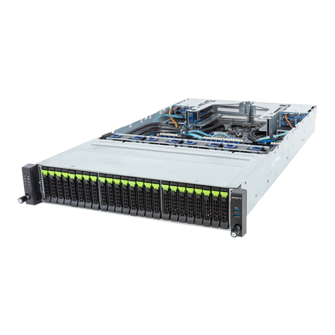
NMS Communications Vision VS 5000 Instruction Manual

100 Crossing Boulevard
Framingham, MA 01702-5406 US
A
www.nmscommunications.com
Installing the Vision VS 5000
Server
9000-62672-10

Installing the Vision VS 5000 Server
2 NMS Communications
No part of this document may be reproduced or transmitted in any form or by any means without prior
written consent of NMS Communications Corporation.
© 2007 NMS Communications Corporation. All Rights Reserved.
Alliance Generation is a registered trademark of NMS Communications Corporation or its subsidiaries. NMS
Communications, Natural MicroSystems, AG, CG, CX, QX, Convergence Generation, Natural Access,
Natural Access MX, CT Access, Natural Call Control, Natural Media, NaturalFax, NaturalRecognition,
NaturalText, Fusion, Open Telecommunications, Natural Platforms, NMS HearSay, AccessGate, MyCaller,
and HMIC are trademarks or service marks of NMS Communications Corporation or its subsidiaries. Multi-
Vendor Integration Protocol (MVIP) is a registered trademark of GO-MVIP, Inc. UNIX is a registered
trademark in the United States and other countries, licensed exclusively through X/Open Company, Ltd.
Windows NT, MS-DOS, MS Word, Windows 2000, and Windows are either registered trademarks or
trademarks of Microsoft Corporation in the United States and/or other countries. Clarent and Clarent
ThroughPacket are trademarks of Clarent Corporation. Sun, Sun Microsystems, Solaris, Netra, and the Sun
logo are trademarks or registered trademarks of Sun Microsystems, Inc. in the United States and/or other
countries. All SPARC trademarks are used under license and are trademarks or registered trademarks of
SPARC International, Inc. in the United States and/or other countries. Products bearing SPARC trademarks
are based upon an architecture developed by Sun Microsystems, Inc. Linux is a registered trademark of
Linus Torvalds. Red Hat is a registered trademark of Red Hat, Inc. All other marks referenced herein are
trademarks or service marks of the respective owner(s) of such marks. All other products used as
components within this product are the trademarks, service marks, registered trademarks, or registered
service marks of their respective owners.
Every effort has been made to ensure the accuracy of this manual. However, due to the ongoing
improvements and revisions to our products, NMS Communications cannot guarantee the accuracy of the
printed material after the date of publication or accept responsibility for errors or omissions. Revised
manuals and update sheets may be published when deemed necessary by NMS Communications.
P/N 9000-62672-10
Revision history
Revision
Release date
Notes
1.0 March 2007 SRG, VS 5000 Server Release 1.0
Last modified: March 7, 2007
Refer to www.nmscommunications.com for product updates and for information
about support policies, warranty information, and service offerings.

NMS Communications 3
Table Of Contents
Chapter 1:Introduction .................................................................................5
Vision VS 5000 Server overview .................................................................... 5
Rear panel ................................................................................................. 5
Accessing Vision documentation .................................................................... 6
Chapter 2:Ethernet and SS7 signaling interfaces ..........................................7
SS7 signaling link (trunk) connectors and LEDs ............................................... 7
Ethernet connectors and LEDs....................................................................... 8
Chapter 3:Installation overview....................................................................9
Connecting to a T1 network .........................................................................10
Chapter 4:Cabling the server ......................................................................11
Connecting to the serial management (ALOM) port..........................................12
Prerequisites...........................................................................................12
Connecting the server's Ethernet interface .....................................................14
Connecting VS 5000 Servers for redundancy ..................................................15
Connecting signaling link (trunk) cables.........................................................17
Chapter 5:Compliance information..............................................................19
Compliance statements ...............................................................................19
EU R&TTE statement................................................................................19
FCC Part 15 Class A statement ..................................................................19
FCC Part 68 statement .............................................................................20
Canadian ICES-003 statement...................................................................21
Canadian CS-03 statement .......................................................................21
Compliance and regulatory certification .........................................................22
EMC .........................................................................................................22
Safety ......................................................................................................22
Telecom....................................................................................................22


NMS Communications 5
1
1
Introduction
For models: VSN-VS51004, VSN-VS51016, VSN-VS51032, VSN-VS51H04, VSN-VS52004,
VSN-VS52016, VSN-VS52032, VSN-VS52H04
This document provides an overview of the Vision VS 5000 Server.
Vision VS 5000 Server overview
The Vision VS 5000 Server (Sun Netra 240) is shipped with the following
components:
• Rack mount kit
• Two signaling link adapter cables (NMS P/N 32851)
• AC power cord (if required). Specified per order.
• DB-9 to RJ-45 serial adapter cable
• Ferrite block kit (NMS P/N 2850-34098) for DC servers
• Netra 240 Server Quick Start Guide
• Installing the Vision VS 5000 Server (this document)
• R&TTE Declaration of Conformity
• RoHS Declaration of Conformity
• Software License Agreement
You must provide a crossover Ethernet cable if you are connecting two Vision VS
5000 servers for redundancy support. For more information, refer to Connecting VS
5000 Servers for redundancy on page 15.
Rear panel
The following illustration shows the Vision VS 5000 Server rear panel:
NETMGT SERIALMGT 01
PS1
PCI0 PCI1 PCI2
PCILOCK DOWN
ALARM
Chassis ground studs
Alarm I/O DB-15
connector
Network management
RJ-45 connector
Serial DB-9
connector
Ethernet RJ-45
connectors
USB connectors SCSI
connector
Power connectors Serial management
RJ-45 connector (ALOM)
01 32
Signaling line card with
Ethernet and SS7 signaling interfaces

Introduction Installing the Vision VS 5000 Server
6 NMS Communications
Accessing Vision documentation
The following table summarizes how to access the Vision documentation:
Step Action
1 In a web browser, enter the following URL:
http://www.nmscommunications.com/docs
2 Select Signaling Server from the list of products.
3 Select Signaling Server VS 5000 Release 1.
A list of Vision Signaling Server manuals displays.
4 Select the manual that you want to Download, View, or Print.
5 Enter the following password at the prompt: vs0925
You can then download, view, or print the manual.

NMS Communications 7
2
2
Ethernet and SS7 signaling
interfaces
The signaling line card in the Vision VS 5000 Server has the following types of
connectors and LEDs:
• SS7 signaling link (trunk) connectors and LEDs
• Ethernet connectors and LEDs
Ethernet connectors
4
3
2
1
Ethernet 1 Ethernet 2
100 LED
LINK/ACT LED
SS7
trunks 2
and 4
SS7
trunks 1
and 3
NET MGT SERIAL MGT 01
PS1
PCI0 PCI1 PCI2
PCI LOCKDOWN
ALARM
01 32
SS7 signaling link
(trunk) connectors
SS7 signaling
link (trunk) LEDs
SS7 signaling link (trunk) connectors and LEDs
There is one green LED for each SS7 signaling link. The signaling link LEDs provide
the following indications:
LEDs Description
Off Trunk is not configured.
Slow blinking green Loss of signal.
Fast blinking green Loss of frame or loss of signaling multiframe.
Steady green Proper frame synchronization between the trunk and network is established, and
all required framing alignment was found.

Ethernet and SS7 signaling interfaces Installing the Vision VS 5000 Server
8 NMS Communications
Ethernet connectors and LEDs
The two Ethernet connectors on the signaling line card have LEDs that indicate the
status of each Ethernet interface. The LEDs are located in the RJ-45 connectors as
shown in the previous illustration. The following table describes the functionality of
each LED:
LED Description
LINK/ACT Status of the Ethernet link. When the Ethernet link has established link integrity, the LED is
on and steady. It also indicates the transmitting and receiving activity on the link. When
activity is present on the Ethernet link, the LED flickers.
100 Data rate of the Ethernet link. When the LED is on, the data rate is 100 Mb. When the LED is
off, the data rate is 10 Mb. The LED is used only when a reliable Ethernet connection has
been established. (The LINK/ACT LED is on.)

NMS Communications 9
3
3
Installation overview
Warning:
Observe the following precautions when handling Vision VS 5000 Server equipment:
Server power ON/OFF: The push-button on/off power switch on the front panel of the
server does not turn off the power. To remove power from the server, you must unplug
the power cord from either the power supply or wall outlet.
Hazardous conditions
• Power supply:
Hazardous voltage, current, and energy levels are present inside the power
supply enclosure.
• Devices and cables:
Hazardous electrical conditions may be present on power, telephone, and
communication cables. Turn off the server and disconnect telecommunications
systems, networks, modems, and the power cord attached to the server before
opening it. Otherwise, personal injury or equipment damage can result.
Maintenance: There are no user-serviceable parts inside the Vision VS 5000 Server
chassis. Only technically qualified personnel should perform service and maintenance
tasks.
Avoid injury: Lifting the server chassis and attaching it to the rack is a two-person job. If
needed, use an appropriate lifting device. A fully loaded Vision VS 5000 Server (not
including the mounting brackets) weighs approximately 16.53 kg (36.40 lbs).
Caution: Temperature: The operating temperature of the server, when installed in an equipment
rack, must not go below 5 °C (41 °F) or rise above 40 °C (104 °F). Extreme fluctuations in
temperature can cause a variety of problems in the server.
Ventilation: The equipment rack must provide sufficient airflow to the front of the server
to maintain proper cooling.
Codes and regulations: Ensure that the installation meets all government codes and
regulations concerning facilities. In addition, all sites where the Vision VS 5000 Servers are
deployed must meet all local, national, and international codes described in Compliance
statements on page 19 and Compliance and regulatory certification on page 22.

Installation overview Installing the Vision VS 5000 Server
10 NMS Communications
The following table summarizes the steps required for installing the Vision VS 5000
Server:
Step Action
1 Refer to the Netra 240 Server Quick Start Guide for information about installing the Vision VS
5000 Server.
2 Make a good low impedance connection to earth ground. This is required because DS-1
connections can be susceptible to lightning strike or power cross before a power source is
provided for the device. Ensure that T1 connections are behind a channel service unit (CSU).
Refer to Connecting to a T1 network on page 10 for information.
3 Provide a power source for the server.
For DC servers, you must use a ferrite block for each DC power cable. Refer to the ferrite block
kit (NMS P/N 2850-34098) that is shipped with the server.
4 Connect a laptop or workstation to the server's serial management (ALOM) port to reconfigure
the server IP address for your network. For information, refer to Connecting to the serial
management (ALOM) port on page 12.
5 Connect the server's Ethernet 0 to the IP network. For information, refer to Connecting the
server's Ethernet interface on page 14.
6 If appropriate, connect two VS 5000 servers for redundancy. For information, refer to
Connecting VS 5000 Servers for redundancy on page 15.
7 Connect device signaling link (trunk) interfaces. For information, refer to Connecting signaling
link (trunk) cables on page 17.
Once installation is complete, configure the Vision VS 5000 Server as described in
the Vision Signaling Server Configuration and Administration Manual. For information
about accessing this manual, refer to Accessing Vision documentation on page 6.
Connecting to a T1 network
For typical T1 communications, each signaling link (trunk) interface connects to a
channel service unit (CSU), which is connected to a T1 trunk line. The CSU provides
a DSX-1 interface to the T1 line, and also contains circuitry that enables the central
office (CO) to perform diagnostic tests remotely.
The following illustration shows the Vision Server signaling link (trunk) interface with
the CSU:
CSU
DSX-1
interface
T1
trunk
Public service
telephone network
Vision
Server
You can purchase or lease the CSU from the telephone company or other vendor.
Warning:
The cables attached to this product must be isolated by a channel service unit (CSU)
before the cables leave the building.
To avoid causing T1 service provider alarms, make sure that the Vision Server
always sends a valid signal, either by looping back at the CSU or by connecting the
CSU to a functioning Vision Server. The best way to provide a loopback is to unplug
the cable from the Vision Server to the CSU. The modular connector on most CSUs
loops back the transmit signal to the receive signal when nothing is plugged in.

NMS Communications 11
4
4
Cabling the server
This topic describes how to connect the following interfaces:
• Serial management (ALOM) port
• Server's Ethernet interface
• Two servers for redundancy
• Signaling link (trunk) cables

Cabling the server Installing the Vision VS 5000 Server
12 NMS Communications
Connecting to the serial management (ALOM) port
The Vision VS 5000 Server is configured for standalone SS7 operation with a default
IP address. You must reconfigure the server IP address for your network by logging
into the system using a laptop or workstation with terminal emulation software
connected to the serial management (ALOM) port. You can then reconfigure the
server IP parameters to match your network and, optionally, configure the IP
address of the mate server, if it is to be part of a redundant server pair.
The following illustration shows the pinout of the serial management (ALOM) port:
Pin 8: Clear to Send
Pin 7: Data Set Ready
Pin 6: Receive Data
Pin 5: Ground
Pin 4: Ground
Pin 3: Transmit Data
Pin 2: Data Terminal Ready
Pin 1: Request to Send
Pin 1
Pin 8
If you need to connect to the serial management (ALOM) port using a cable with a
DB-9 connector, use the adapter shipped with the server to perform the crossovers
given for each connector. The RJ-45 to DB-9 adapter is wired as described in the
following table:
Serial port (RJ-45 connector) DB-9 adapter
Pin Signal description Pin Signal description
1 RTS (Request to send) 8 CTS (Clear to send)
2 DTR (Data terminal ready) 6 DSR (Data set ready)
3 TXD (Transmit) 2 RXD (Receive)
4 GND (Signal ground) 5 GND (Signal ground)
5 GND (Signal ground) 5 GND (Signal ground)
6 RXD (Receive) 3 TXD (Transmit)
7 DSR (Data set ready) 4 DTR (Data terminal ready)
8 CTS (Clear to send) 7 RTS (Request to send)
Prerequisites
• Laptop or workstation with Hyperterminal and a DB-9 serial port
• DB-9 to RJ-45 serial adapter (shipped with the server)
• RJ-45 serial cable is required for direct serial access to ALOM

Installing the Vision VS 5000 Server Cabling the server
NMS Communications 13
The following table describes the steps for connecting to the serial management
(ALOM) port:
Step Action
1 Connect the laptop or workstation to the ALOM port on the Vision VS 5000 Server by:
• Connecting the laptop serial port (DB-9 connector) to the DB-9 to RJ-45 end of the serial
adapter cable.
• Connect the RJ-45 to RJ-45 end of the serial adapter cable to the serial management RJ-45
connector on the VS 5000 Server.
The following illustration shows the VS 5000 server connected to a laptop:
Serial port cable
An illusion that exalt s us
is more dear
then a thousand sober tr uths...
Laptop running terminal emulator
NET MGT SERIAL MGT 01
PS1
PCI0 PCI1 PCI2
PCI LOCK DOWN
ALARM
0132
Serial management RJ-45 connector (ALOM)
2 Log in at the console prompt.
Reconfigure the server IP address, host name, DNS server, and time zone. You can also configure this
server to be a member of a redundant pair at this point. For information about configuring the server IP
address, refer to the Vision Signaling Server Configuration and Administration Manual.
3 Connect the server to the IP network and access it from other devices using telnet or rsh.
4 Remove the connection to the ALOM port.
Note: The ALOM port is also used for other advanced server administration and
maintenance purposes. Refer to the Sun Netra 240 Server System Administration
Guide and the Sun Advanced Lights Out Manager Software User’s Guide for
information.

Cabling the server Installing the Vision VS 5000 Server
14 NMS Communications
Connecting the server's Ethernet interface
The VS 5000 Server has four Ethernet interfaces as shown in the following
illustration. The Ethernet interface labeled 0 is used for Ethernet communications
with the site network. Connect Ethernet 0 to the IP network. The Ethernet 0
connectors on the two VS 5000 Servers must be connected to the IP network to
communicate with each other. This does not need to be a private link.
NET MGT SERIALMGT 01
PS1
PCI0 PCI1 PCI2
PCILOCK DOWN
ALARM
Ethernet 0
0132
Ethernet RJ-45 connectors
The following illustration shows the pinout of each of the RJ-45 interfaces:
Pin 8: Transmit/Receive Data 3 -
Pin 7: Transmit/Receive Data 3 +
Pin 6: Transmit/Receive Data 1 -
Pin 5: Transmit/Receive Data 2 -
Pin 4: Transmit/Receive Data 2 +
Pin 3: Transmit/Receive Data 1 +
Pin 2: Transmit/Receive Data 0 -
Pin 1: Transmit/Receive Data 0 +
Pin 1
Pin 8

Installing the Vision VS 5000 Server Cabling the server
NMS Communications 15
Connecting VS 5000 Servers for redundancy
The redundancy feature enables an application or service to remain operational in
case of a server failure.
The signaling line card in the Vision VS 5000 Server has two 10/100Base-T Ethernet
connectors. These connectors provide Ethernet connections that support
auto-negotiation for 100Base-T full duplex/half duplex and 10Base-T full duplex/half
duplex transmission. The Ethernet connectors provide a high-speed interface for
connecting a VS 5000 Server to a redundant server.
The following illustration shows the pinouts of the 10/100Base-T Ethernet RJ-45
connectors:
Pins 4, 5, 7, and 8 are grounded through a
spark gap for 100Base-T Ethernet connections
LINK/ACT LED
100 LED
Pin 1
Pin 8
Pin 1: T - Transmit to network
Pin 2: R - Transmit to network
Pin 3: T1 - Receive from network
Pin 4: Ground
Pin 5: Ground
Pin 6: R1 - Receive from network
Pin 7: Ground
Pin 8: Ground
The Ethernet connectors in the signaling line card of the two Vision VS 5000 Servers
are connected through a private Ethernet link. To connect a Vision VS 5000 Server to
its redundant mate, you must provide a crossover Ethernet cable. The following
illustration shows a crossover cable (P/N 6000-34080) that is available from NMS:
8
1
Pin 1
Pin 8
Side BSide A
With one crossover cable, connect the Ethernet 1 on each server.

Cabling the server Installing the Vision VS 5000 Server
16 NMS Communications
The following table provides the pin assignments for this crossover cable:
Side A Side B
1 3
2 6
3 1
4 7
5 8
6 2
7 4
8 5
The following illustration shows how to set up two Vision VS 5000 Servers as a
redundant pair:
Backup
Vision VS 5000 Server
Primary
Vision VS 5000 Server
SS7 links
on DS1 trunks
Private Ethernet connection
Ethernet 1 Ethernet 1

Installing the Vision VS 5000 Server Cabling the server
NMS Communications 17
Connecting signaling link (trunk) cables
The following illustration shows pinouts of the T1/E1 8-pin modular jacks on the
Vision VS 5000 Server:
Pin 8: (Port 2) R - Receive from network
Pin 7: (Port 2) T - Receive from network
Pin 6: (Port 2) R1 - Transmit to network
Pin 5: (Port 1) T1 - Transmit to network
Pin 4: (Port 1) R1 - Transmit to network
Pin 3: (Port 2) T1 - Transmit to network
Pin 2: (Port 1) T - Receive from network
Pin 1: (Port 1) R - Receive from network
Pin 1
Pin 8
To access Trunk 1, Trunk 2, or both Trunk 1 and Trunk 2, connect a shielded T1 or
E1 RJ-48 cable to one or both 8-pin modular jacks.
To access all four trunks, use the two trunk adapter cables (NMS P/N 32851). Each
trunk adapter cable separates the 8-pin modular jack on the end bracket into two
RJ-48C connectors.
The following illustration shows the trunk adapter cable:
NMS RJ-45
Length: 4 “
RJ-48C
Jack 1/3
Jack 2/4
The following illustration shows the pinouts of the RJ-48C connectors on the trunk
adapter cable:
Pin 8: Optional shield, not used
Pin 7: Optional shield, not used
Pin 6: No connection
Pin 5: T1 - Transmit to network
Pin 4: R1 - Transmit to network
Pin 3: No connection
Pin 2: T - Receive from network
Pin 1: R - Receive from network
Pin 1
Pin 8


NMS Communications 19
5
5
Compliance information
This topic provides the following information:
• Compliance statements
• Compliance and regulatory certification
Compliance statements
EU R&TTE statement
This product is intended to be connected to a 2048 kbit/s 120 ohm digital structured
or unstructured ONP leased line in all EU countries.
A copy of the R&TTE Declaration of Conformity is shipped with the product.
FCC Part 15 Class A statement
This board has been tested and found to comply with the limits for a Class A digital
device, pursuant to Part 15 of the FCC Rules. These limits are designed to provide
reasonable protection against harmful interference when the equipment is operated
in a commercial environment. This equipment generates, uses, and can radiate radio
frequency energy and, if not installed and used in accordance with the instruction
manual, may cause harmful interference to radio communications. Operation of this
equipment in a residential area is likely to cause harmful interference, in which case
the user will be required to correct the interference at his or her own expense.
Modifications not expressly approved by NMS may void the FCC granted authority to
operate the equipment.

Compliance information Installing the Vision VS 5000 Server
20 NMS Communications
FCC Part 68 statement
This equipment complies with Part 68 of the FCC rules and the requirements adopted
by the ACTA. On the bottom of this equipment is a label that contains, among other
information, a product identifier in the format US:EMCXDNANXXXXXXXX. If
requested, this number must be provided to the telephone company.
The telephone company will need to know the Service Order Code, the Facility
Interface Code, and the wiring configuration (or USOC jack type) corresponding to
the service you are ordering, as shown in the following table:
Service type Facility interface
code
Service
order code
USOC
jack type
4-wire 1.544 Mbps (DS1) with super frame (SF),
alternate mark inversion (AMI), no line power,
100 ohms.
04DU9-BN 6.0N RJ-48C
4-wire 1.544 Mbps (DS1) with SF, bipolar with
eight-zero substitution (B8ZS), no line power,
100 ohms.
04DU9-DN 6.0N RJ-48C
4-wire 1.544 Mbps (DS1) with extended super
frame (ESF), AMI, no line power, 100 ohms.
04DU9-1KN 6.0N RJ-48C
4-wire 1.544 Mbps (DS1) with ESF, bipolar with
eight-zero substitution (B8ZS), no line power,
100 ohms.
04DU9-1SN 6.0N RJ-48C
If the equipment causes harm to the telephone network, the telephone company will
notify you in advance that temporary discontinuance of service may be required. If
advance notice is not practical, the telephone company will notify you as soon as
possible. Also, you will be advised of your right to file a complaint with the FCC if you
believe it is necessary.
The telephone company may make changes in its facilities, equipment, operations, or
procedures that could affect the operation of the equipment. If this happens the
telephone company will provide advance notice so that you can make necessary
modifications to maintain uninterrupted service.
This product is not intended for customer repair.
If you experience trouble with this equipment, contact NMS for warranty and repair
information. The telephone company may ask that you disconnect this equipment
from the network until the problem has been corrected or until you are sure that the
equipment is not malfunctioning. This board may not be connected to party lines or
used on coin service lines provided by the telephone company. The part 68 affidavit
for digital and subrate services is included separately.
Table of contents
