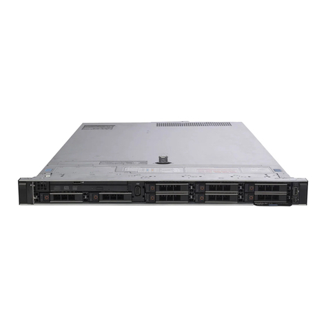
Fortinet FortiADC 1200F User manual

FortiADC 1200F
QuickStart Guide

Product Registration
Thank you for purchasing a Fortinet FortiADC. To access:
http://support.fortinet.com
▪ Cloud Management ▪FortiGuard Updates ▪Firmware Upgrades
▪Technical Support ▪Warranty Coverage
Please register your Fortinet FortiADC:
Vous devez enregistrer le produir:
Debe registrar el producto:
登録のお願い:
请马上注册:
This guide covers: FAD-1200F, FAD-1200F-DC
October 17, 2022
Copyright© 2020 Fortinet, Inc. All rights reserved. Fortinet®, FortiGate®, FortiCare® and FortiGuard®, and certain other marks are registered trademarks
of Fortinet, Inc., in the U.S. and other jurisdictions, and other Fortinet names herein may also be registered and/or common law trademarks of Fortinet. All
other product or company names may be trademarks of their respective owners. Performance and other metrics contained herein were attained in internal
lab tests under ideal conditions, and actual performance and other results may vary. Network variables, different network environments and other conditions
may affect performance results. Nothing herein represents any binding commitment by Fortinet, and Fortinet disclaims all warranties, whether express or
implied, except to the extent Fortinet enters a binding written contract, signed by Fortinet’s General Counsel, with a purchaser that expressly warrants that
the identified product will perform according to certain expressly-identified performance metrics and, in such event, only the specific performance metrics
expressly identified in such binding written contract shall be binding on Fortinet. For absolute clarity, any such warranty will be limited to performance
in the same ideal conditions as in Fortinet’s internal lab tests. In no event does Fortinet make any commitment related to future deliverables, features or
development, and circumstances may change such that any forward-looking statements herein are not accurate. Fortinet disclaims in full any covenants,
representations, and guarantees pursuant hereto, whether express or implied. Fortinet reserves the right to change, modify, transfer, or otherwise revise this
publication without notice, and the most current version of the publication shall be applicable.
For Product License Agreement / EULA and Warranty Terms, visit https://www.fortinet.com/content/dam/fortinet/assets/legal/EULA.pdf

5
2x Power Cables
(AC models only)
1x Ethernet Cable
1x Console Cable
(DB9 to RJ45)
4
QuickStart Guide
FortiADC 1200F
Contents - FAD 1200F
Optional SFP Transceiver Modules
FN-TRAN-SX, 1 GE SFP SX transceiver module for all systems with SFP and SFP/SFP+ slots
FN-TRAN-LX, 1 GE SFP LX transceiver module for all systems with SFP and SFP/SFP+ slots
FN-TRAN-GC, 1 GE SFP RJ45 transceiver module for all systems with SFP and SFP/SFP+slots
1x Accessory Kit
(2x Rails, 2x Rail Screws,
4x Rubber Feet, 2x Rackmount Ears)
2x DC Connectors
(DC Models only)
Front Panel - FAD 1200F
1 2
2
4 5 6
3
3
5
4
6
CONSOLE (RJ45) port for serial port management
USB (USB A x2) USB 3.0 server port
Management Port (RJ45) GE device management, default IP is 192.168.1.99
HA (RJ45) GE high availability port
Ports 17 to 24 (SFP+) 10 GE / GE SFP slots
Ports 9 to 16 (SFP) GE SFP slots
Ports 1 to 8 (RJ45) GE SFP slots
Green:Link established at 10 or 1 Gbps
Flashing Green: Transmitting data
Off: No link established
1
Power Supply Alarm
Amber: Power supply failure
Off: Normal operation
System LED Indicators
Power Supply Fan Alarm
Amber: Fan failure
Off: Normal operation
Hard Disk Alarm
Flashing Red: Data activity
Off: Normal operation
System Power Indicator
Green: Power on
Off: Power off
Green: Link established at 1 Gbps
Flashing Green:Transmitting data at 1 Gbps
Amber:Link establised at 100 Mbps
Flashing Amber: Transmitting data at 100 Mbps
Off: No link established
Green: Link established at 1 Gbps
Flashing Green:Transmitting data at 1 Gbps
Amber:Link establised at 100 Mbps
Flashing Amber: Transmitting data at 100 Mbps
Off: No link established

76
Rear Panel - FAD 1200F Rear Panel - FAD 1200F-DC
CAUTION/ATTENTION
SHOCKHAZARD. DISCONNECT ALL POWER SOURCES.
RISQUED’ÉLECTROCUTION. DÉBRANCHEZ TOUTES LES
SOURCESD’ALIMENTATION.
3 31 12 24 4
Power Supply Indicator
Power Alarm Button resets a power supply error Power Alarm Button resets a power supply error
Redundant Power Supplies (x2) 100 to 240V AC, 7-3.5A, 50/60Hz Redundant Power Supplies (x2) -48V DC to -60V DC, 20A
Power Switch turns the power ON/OFF Power Switch turns the power ON/OFF
4
2 2
3 3
1 1
Green: Power supply operating normally
Flashing Green (1 sec): AC input but in Active-Standby mode
Amber: AC input power failure; second power supply operating normally
Off: No AC input
DC Power Supply Indicator
4
Green: PSU operating normally
Flashing Green (1 sec): DC power present but in Active-Standby mode
Amber: DC input power failure; second power supply operating normally
Flashing Amber: PSU warning event
Off: No DC input

98
AC Installation
Plug in your device to a power outlet using the provided power cables.
Power Outlet
or UPS
Power Outlet
or UPS
Power Connection
Power Connection
Supplied Power Cable
Supplied Power Cable
Note: We recommend connecting your FortiADC to an uninterruptible power
supply (UPS) in case of a power outage
DC Cable Installation
Plug in your device to a power outlet using the provided DC power cables.
Assemble the power cables using the supplied power connector.
Pin 1 (-)
Pin 2 (+) Pin 2 (+) Pin 3 ( )
Pin 1 (-)Pin 3 ( )
DC PSU1
DC PSU2
Note: Pin 1 is Negative. Pin 2 is Positive. Pin 3 is Ground. Cables and terminal
lugs are not included. The wires are rated between 24-10 AWG.
Note: We recommend connecting your FortiADC to an uninterruptible power
supply (UPS) in case of a power outage
(Power cable assembly)
(Power cable assembly)
DC Power Terminals
DC Power Terminals

1110
Rack Installation
The supplied equipment is designed for standard 19inch racks. The rails
provided are specially designed for this model.
Rack Stability
Ensure the rack is stable before installing the slide rails and appliance.
• Check that the leveling jacks on the bottom of the rack are fully extended to the
floor with the full weight of the rack resting on the jacks
• For single rack installation, stabilizers should be attached to the rack; for multiple
rack installations, the racks should be coupled together
Support
For video support on installing these slide rails, please visit:
For additional support, please visit:
Appliance Installation
• To avoid personal injury or equipment damage, use a lifting device
• Do not pick up the appliance by the front handles
• Each inner rail has a system lock out tab to prevent the appliance from sliding out,
ensure that it is locked when installing the appliance
• Prevent Electrostatic discharge (ESD) damage by wearing antistatic devices
• Do not place heavy objects on the appliance
What You Will Need
• Philips screwdriver, level & tape measure
• Rack-provided cage nuts and screws
• A lifting device or additional support
• ESD antistatic gear
https://video.fortinet.com
http://support.fortinet.com
Rail Assembly
• The rail kit includes a left and a right rail assembly
• Each rail assembly includes an inner rail, a middle rail, and an outer rail
• The inner rail has locking keyholes used to secure the rail to the appliance
• The inner rail rear end has a lock out tab which slides into the middle rail
• The middle rail is in the outer rail and used to guide the inner rail into the outer rail
• The outer rail has front and rear mounting pins that push into to the rack holes
• The outer rail also has front and rear locking latches to secure the rail to the rack
Inner Rails
Lock Out Tab
Mounting Pins
Release Tab Locking Keyhole
Outer Rails
Locking Latch

1312
2
2
3
4
5
Slide Forward
Install M4 Shoulder Screw
Unlocked
Locked
Attach the Inner Rails to the Appliance
1. Detach the inner rail from the rail assembly by pressing the lock out tab
2. Place an inner rail against a side of the appliance
3. Align the inner rail keyholes with the appliance pins
4. Slide the rail towards the front of the appliance until the metal clip locks into place
5. For inner rails with 5 keyholes and a chassis with 3 pins and a thread hole, use the
provided M4 shoulder screw to secure the rail to the appliance
6. Repeat steps 1 to 5 for the remaining inner rail
Align Rail
Metal Clip
Inner Rail
Inner Rail
Attach the Outer Rails to the Rack
Front Outer Rail
1. Place an outer rail against a side of the rack
2. Align the front outer rail with the front of the rack
3. Push the front outer rail mounting pins into the rack post holes
4. Lock the locking latch to safely secure the front outer rail to the post
Rear Outer Rail
5. Extend the rear outer rail just past the rack post
6. Level the rail and align the mounting pins
7. Push the rear mounting pins into the rack post holes
8. Lock the locking latch to safely secure the rear outer rail to the post
9. Repeat steps 1 to 8 for the remaining outer rail
1
Right Rail
Extend Rail
Mount Rail
Lock Latch
Front Rail
Mount Rail
Lock Latch
2
3
4
6
5
7
8
Align & Level

1514
Install the Appliance
Safety Precautions
1. Check that the inner rails are secured to the appliance
2. Inspect that the rack posts and outer rails are secured and level
Rail Installation
3. Slide the middle outer rails forward until they fully extend and lock into place
4. Using a lifting device, lift the appliance and align the inner rails with the middle rails
5. Slide the appliance and inner rails into the middle rails until there is a stop
System Lock
6. Apply even pressure and slide the release tabs outward while sliding the appliance all
the way into the rack until the system release tabs click and lock into position
7. Use four rack screws (not provided) to secure the appliance to the rack
System Release Button
Inner Rail Metal Clip
Release Tab
System Lock Out Tab
Release Tab
System Lock Out Tab
System Lock Out Tab
Release Tab
1
6
7
2
3
4
5
Check Rail Locks
Inspect Posts
Extend Rails
Align Rails
Slide Rails
Deployment
Fully integrate with Fortinet's Security Fabric to optimize network visibility,
load balancing, and user authentication with your new FortiADC.

16 17
Setup Options
Set up your device locally using the GUI or CLI. Choose an option to
complete your setup, then configure your device.
Local Setup
Command Line Interface (CLI)
An alternate configuration tool from the web-based manager that
uses a terminal emulation application to type commands or upload
batches of commands from a text file or configuration script.
GUI
Local Setup
An easy-to-use GUI, compatible with most web browsers.
To minimize scrolling, the screen resolution should be at least
1280 x 1024 pixels.
A
BEthernet Cable
1. Connect Port 1 to the Management Computer using the supplied Ethernet cable
2. Enable DHCP or set the Management Computer’s IP and subnet to:
Static IP Address: 192.168.1.1
Subnet Mask: 255.255.255.0
3. Visit 192.168.1.99 in a web browser
4. Log in with username admin and no password
5. You can now configure your FortiADC
Management Computer
Port 1
Browse to 192.168.1.99
Username: admin
No Password
GUI
A

1918
CLI
B
1. Connect the Console Port with a console cable to the Serial Port on the
Management Computer
2. Start a terminal program on the Management Computer and select an available
COM Port using the following default settings:
Baud rate: 9600
Data bits: 8
Parity: None
Stop bits: 1
Flow control: None
3. Log in using username admin and no password
4. You can now configure your FortiADC
Console Port
Serial Port
Console Cable
Basic Settings
Please refer to the admin guide found on
docs.fortinet.com
for detailed
instruction on configuring your FortiADC.
Basic Network Settings
1. Once you have installed your FortiADC and configured your management interface,
we recommend setting the following:
Administrative password
System time and date
Network interfaces
DNS
2. Test the connectivity between devices
3. Register your product, if you haven't already
4. Install your license and update the firmware
5. Configure a basic load balancing policy
6. Test the deployment with a load to verify the system behavior
7. Back up your configuration to have as a restore point

21
Resources
Refer to the following resources to continue your FortiADC setup.
Fortinet Customer Service & Support
Create a support account, register and manage your products,
download updates, firmware images and release notes, and
create technical support tickets.
https://support.fortinet.com
Fortinet Document Library
Up-to-date versions of Fortinet publications for the entire family
of Fortinet products.
https://docs.fortinet.com
Training Services
Course descriptions, availability, schedules, and location of
training programs in your area.
https://www.fortinet.com/support-and-training/training.html
Technical Discussion Forums
Communicate with other customers and Fortinet partners about
Fortinet products, services, and configuration issues.
https://support.fortinet.com/forum
FortiGuard Threat Research and Response
Up-to-date information on vulnerabilities and threats, includes a
virus scanner, IP signature look-up, and web filtering tools.
https://fortiguard.com
Cautions and Warnings
Environmental Specifications
Ambient operating temperature: 0°C to 40°C
Rack Mount Instructions - The following or similar rack-mount instructions are included with the installation instructions:
Instructions de montage en rack - Les instructions de montage en rack suivantes ou similaires sont incluses avec les instructions d'installation:
Elevated Operating Ambient - If installed in a closed or multi-unit rack assembly, the operating ambient temperature of the rack environment may
be greater than room ambient. Therefore, consideration should be given to installing the equipment in an environment compatible with the maximum
ambient temperature (Tma) specified by the manufacturer.
Température ambiante élevée -S'il est installé dans un rack fermé ou à unités multiples, la température ambiante de fonctionnement de
l'environnement du rack peut être supérieure à la température ambiante de la pièce. Par conséquent, il est important d’installer le matériel dans un
environnement respectant la température ambiante maximale (Tma) stipulée par le fabricant.
Reduced Air Flow -Installation of the equipment in a rack should be such that the amount of air flow required for safe operation of the equipment is
not compromised.
Ventilation réduite -Installation de l'équipement dans un rack doit être telle que la quantité de flux d'air nécessaire au bon fonctionnement de
l'équipement n'est pas compromise.
Mechanical Loading -Mounting of the equipment in the rack should be such that a hazardous condition is not achieved due to uneven mechanical
loading.
Chargement Mécanique -Montage de l'équipement dans le rack doit être telle qu'une situation dangereuse n'est pas lié à un chargement mécanique
inégal.
Circuit Overloading -Consideration should be given to the connection of the equipment to the supply circuit and the effect that overloading of the
circuits might have on overcurrent protection and supply wiring. Appropriate consideration of equipment nameplate ratings should be used when
addressing this concern.
Surtension -Il convient de prendre l’ensemble des précautions nécessaires lors du branchement de l’équipement au circuit d’alimentation et être
particulièrement attentif aux effets de la suralimentation sur le dispositif assurant une protection contre les courts-circuits et le câblage. Ainsi, il est
recommandé de tenir compte du numéro d’identification de l’équipement.
Reliable Earthing -Reliable earthing of rack-mounted equipment should be maintained. Particular attention should be given to supply connections
other than direct connections to the branch circuit (e.g. use of power strips).
Fiabilité de la mise à la terre -Fiabilité de la mise à la terre de l'équipement monté en rack doit être maintenue. Une attention particulière devrait
être accordée aux connexions d'alimentation autres que les connexions directes au circuit de dérivation (par exemple de l'utilisation de bandes de
puissance).
Refer to specific Product Model Data Sheet for Environmental Specifications (Operating Temperature, Storage Temperature, Humidity, and Altitude)
Référez à la Fiche Technique de ce produit pour les caractéristiques environnementales (Température de fonctionnement, température de stockage,
humidité et l'altitude).
Safety
Moving parts — Hazardous moving parts. Keep away from moving fan blades.
Pièces mobiles – Pièces mobiles dangereuses. Se tenir éloigné des lames mobiles du ventilateur.
Warning: Equipment intended for installation in Restricted Access Location.
Avertissement: Le matériel est conçu pour être installé dans un endroit où l’accès est restreint.
Warning: A readily accessible disconnect device shall be incorporated in the building installation wiring.
Avertissement: Un dispositif de déconnexion facilement accessible doit être incorporé dans l'installation électrique du bâtiment.
Warning: A UL Listed external disconnect device, i.e. circuit breaker or other, with over current protection suitable for local code(rated 25A
recommended) shall be installed with this equipment
Avertissement: Un dispositif de déconnection externe homologué UL, exemple d'un disjoncteur ou autre, avec des protections de surintensité
appropriées (nominal 25A recommandé) à I'installation de ce matériel.
Battery – Risk of explosion if the battery is replaced by an incorrect type. Do not dispose of batteries in a fire. They may explode. Dispose of used
batteries according to your local regulations. IMPORTANT: Switzerland: Annex 4.10 of SR814.013 applies to batteries.
Batterie – Risque d'explosion si la batterie est remplacée par un type incorrect. Ne jetez pas les batteries au feu. Ils peuvent exploser. Jetez les piles
usagées conformément aux réglementations locales. IMPORTANT: Suisse: l'annexe 4.10 de SR814.013 s’appliquent aux batteries.
警告
本電池如果更換不正確會有爆炸的危險
請依製造商說明書處理用過之電池
CAUTION:
There is a danger of explosion if a battery is incorrect replaced. Replace only with the same or equivalent type.
Dispose batteries of according to the manufacturer’s instructions.
Disposing a battery into fire, a hot oven, mechanically crushing, or cutting it can result in an explosion.
Leaving a battery in an extremely hot environment can result in leakage of flammable liquid, gas, or an
explosion.
If a battery is subjected to extremely low air pressure, it may result in leakage of flammable liquid, gas, or an
explosion.
WARNUNG:
Lithium-Batterie Achtung: Explosionsgefahr bei fehlerhafter Batteriewechsel. Ersetzen Sie nur den gleichen oder gleichwertigen Typ. Batterien gemäß
den Anweisungen des Herstellers entsorgen.
Beseitigung einer BATTERIE in Feuer oder einen heißen Ofen oder mechanisches Zerkleinern oder Schneiden einer BATTERIE, die zu einer
EXPLOSION führen kann

2322
Verlassen einer BATTERIE in einer extrem hohen Umgebungstemperatur, die zu einer EXPLOSION oder zum Austreten von brennbarer Flüssigkeit oder
Gas führen kann
Eine BATTERIE, die einem extrem niedrigen Luftdruck ausgesetzt ist, der zu einer EXPLOSION oder zum Austreten von brennbarer Flüssigkeit oder
Gas führen kann.
CAUTION: Shock Hazard. Disconnect all power sources.
ATTENTION: Risque d'électrocution. Débranchez toutes les sources d'alimentation.
Caution: Slide/rail mounted equipment is not to be used as a shelf or a work space.
Attention: Un équipement monté sur bâti ne doit pas être utilisé sur une étagère ou dans un espace de travail.
Warning: Stability hazard.
Aviso: Perigo de estabilidade.
The rack may tip over causing serious personal injury.
O rack pode tombar causando ferimentos graves.
Before extending the rack to the installation position, read the installation instructions.
Antes de estender o rack para a posição de instalação, leia as instruções de instalação.
Do not put any load on the slide-rail mounted equipment in the installation position.
Não coloque nenhuma carga no equipamento montado em trilho deslizante na posição de instalação.
Do not put any load on the slide-rail mounted equipment in the installation position.
Não coloque nenhuma carga no equipamento montado em trilho deslizante na posição de instalação.
Do not leave the slide-rail mounted equipment in the installation position.
Não deixe o equipamento montado em trilho deslizante na posição de instalação.
Regulatory Compliance
Federal Communication Commission (FCC) – USA
This device complies with Part 15 of the FCC Rules. Operation is subject to the following two conditions:
(1) this device may not cause harmful interference, and
(2) this device must accept any interference received; including interference that may cause undesired operation.
This equipment has been tested and found to comply with the limits for a Class A digital device, pursuant to Part 15 of the FCC Rules. These limits are
designed to provide reasonable protection against harmful interference when the equipment is operated in a commercial environment. This equipment
generates, uses, and can radiate radio frequency energy, and if it is not installed and used in accordance with the instruction manual, it may cause harmful
interference to radio communications. Operation of this equipment in a residential area is likely to cause harmful interference, in which case the user will be
required to correct the interference at his own expense.
WARNING: Any changes or modifications to this product not expressly approved by the party responsible for compliance could void the user’s authority to
operate the equipment.
Industry Canada Equipment Standard for Digital Equipment (ICES) – Canada
CAN ICES-003 (A) / NMB-003 (A)
This digital apparatus does not exceed the Class A limits for radio noise emissions from digital apparatus set out in the Radio Interference Regula¬tions of the
Canadian Department of Communications.
Cet appareil numérique n’émet pas de bruits radioélectriques dépassant les limites applicables aux appareils numériques de la classe A prescrites dans le
Règlement sur le brouillage radioélectrique édicte par le ministère des Communications du Canada.
European Conformity (CE) - EU
This is a Class A product. In a domestic environment, this product may cause radio interference, in which case the user may be required to take adequate
measures.
Voluntary Control Council for Interference (VCCI) – Japan
この装置は、クラスA機器です。この装置を住宅環境で使用すると電波妨害を引き起こすことがあります。この場合には
使用者が適切な対策を講ずるよう要求されることがあります
VCCI-A
Product Safety Electrical Appliance & Material (PSE) – Japan
日本では電気用品安全法(PSE)の規定により、同梱している電源コードは本製品の専用電源コードとして利用し、他の製品に使用しないでください。
Bureau of Standards Metrology and Inspection (BSMI) – Taiwan
The presence conditions of the restricted substance (BSMI RoHS table) are available at the link below:
限用物質含有情況表 (RoHS Table) 請到以下 網址下載:
https://www.fortinet.com/bsmi
警告: 為避免電磁干擾,本產品不應安裝或使用於住宅環境。
請仔細閱讀以下說明
本設備勿置於潮濕處。
連接至電源前,請先檢查電壓。
當設備不用時,請將所有電源線拔除,避免電壓不穩而造成傷害。
勿將任何液體濺入設備中,避免線路短路。
基於安全理由,只有受到專業訓練的從業人員,才可以打開本設備。
請勿自行調整或修理已通電的設備,以確保您的安全。
如不小心受傷,請立刻找急救人員給予您適當的救護,千萬別因傷勢輕微而忽略自己的傷勢。
請依照台灣法規處置電池。
若不正確替換電池可能導致爆炸危險,替換電池時,請使用設備生產商推薦使用的電池。
請勿拆卸、刺穿或以其他方式損壞電池。
雷射設備非用戶維修設備,請與生產商聯繫維修事宜。
注意: 要斷開電源,請將所有電源線從本機上拔下
英屬蓋曼群島商防特網股份有限公司台灣分公司
地址:台北市內湖區行愛路176號2樓
電話:(02) 27961666
China
此为A级产品,在生活环境中,该产品可能会造成无线电干扰。这种情况下,可能需要用户对其采取切实可行的措施。
Table of contents
Other Fortinet Server manuals
Popular Server manuals by other brands
Hewlett Packard Enterprise
Hewlett Packard Enterprise HPE ProLiant ML110 Gen10 Maintenance and service guide
Stahl
Stahl ET 8 Series installation manual
Premio
Premio OSS316-D5 quick guide
Silicon Graphics
Silicon Graphics InfiniteStorage C1104-GP6 System user's guide
Rasilient
Rasilient ApplianceStor 75 user manual
Dell
Dell PER4402A Installation and service manual


