NNG NTV-KIT558 User manual

NNG-Ford V1
3950 NW 120th Ave, Coral Springs, FL 33065 TEL 561-955-9770 FAX 561-955-9760
Navigation interface for FORD vehicles equipped with 8.4”MyTouch
NTV-KIT558
NTV-DOC218
SoftTouch Navigation System
2011-2013 Ford Edge Installation Instructions
INSTALLATION PERFORMED ON FORD EDGE FOR REFERENCE ONLY!
Parts Identification Page 1
Vehicle Preparation Page 2
2egaPsgnitteShctiwSgnimmargorP
Installation Page 3
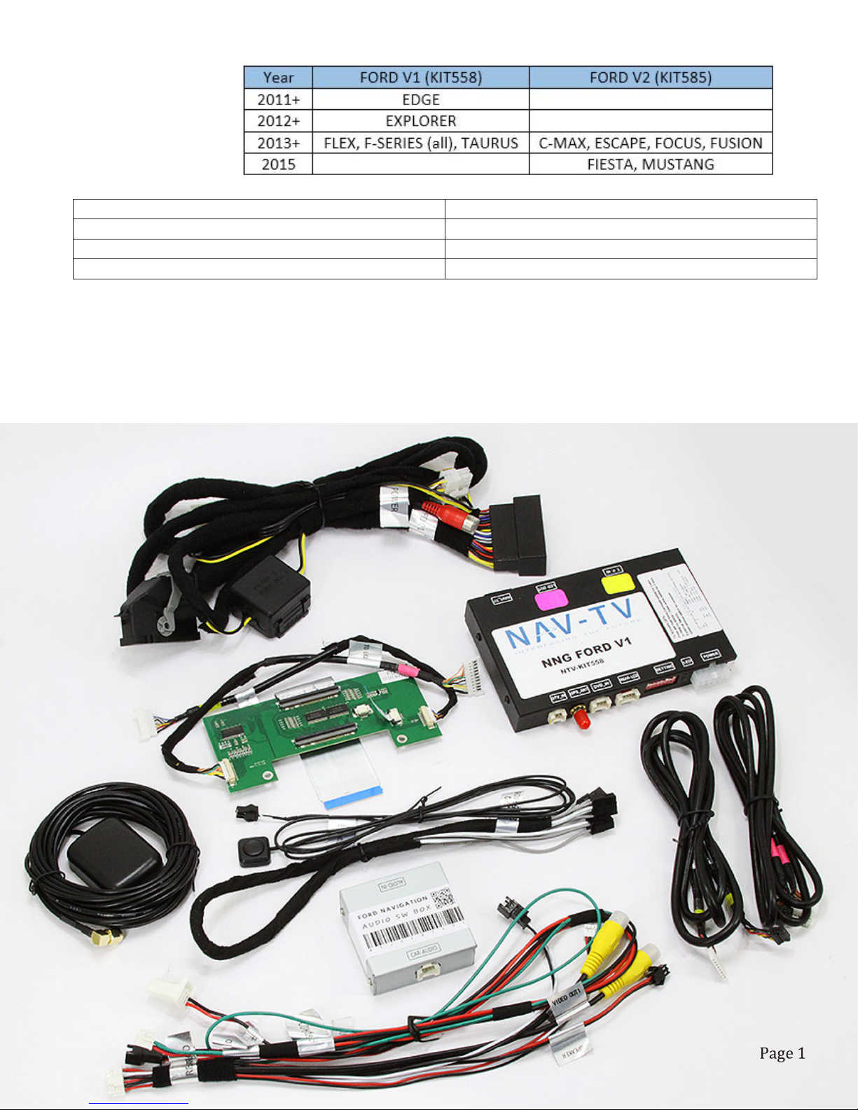
NTV-KIT558: FORD V1
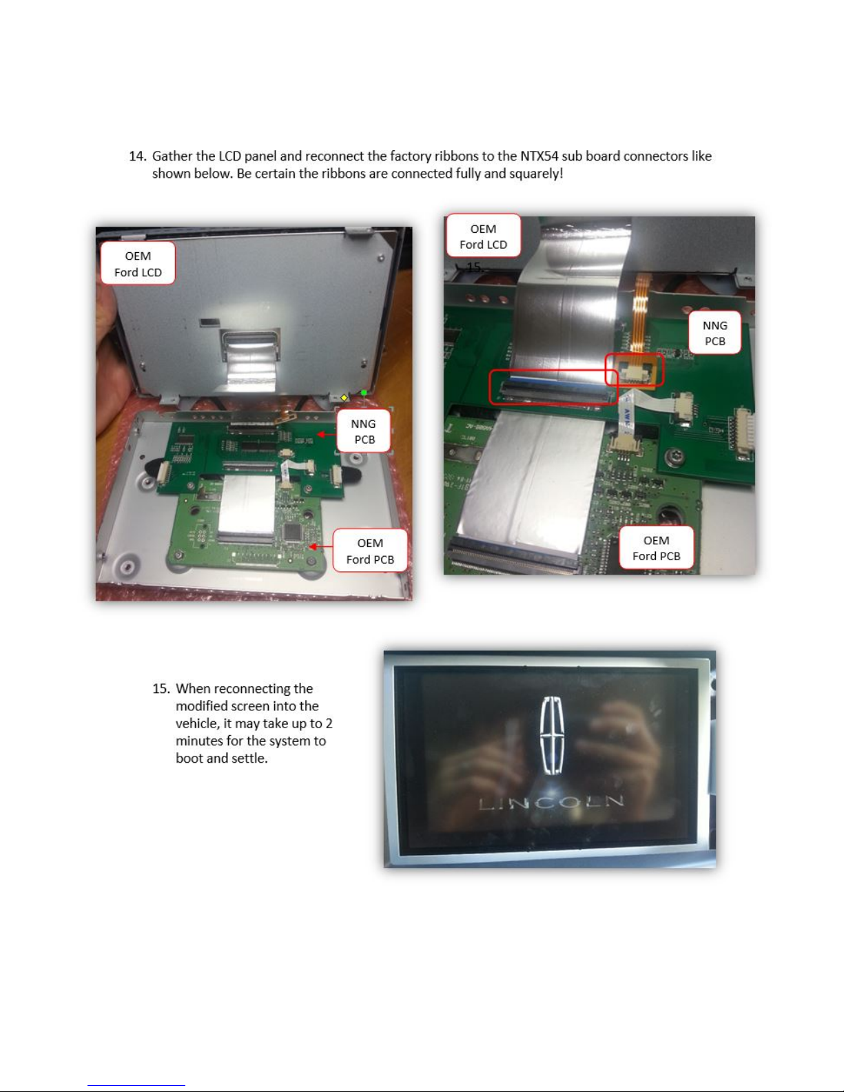
NTV-KIT585: FORD V2
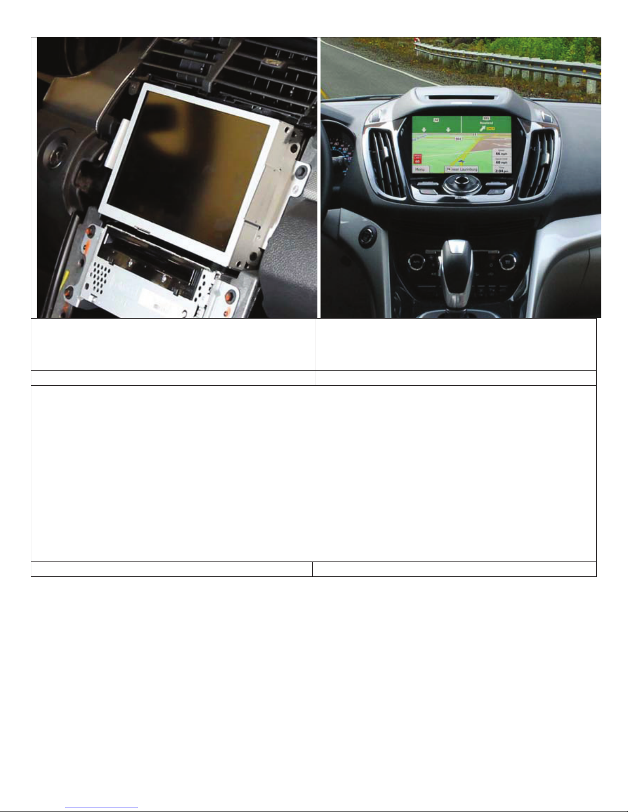
Compatibility
NTV-DOC218
1. NNG-FORD V1 GPS/Interface
2. NNG-FORD V1 Internal Modification PCB
3. NNG-FORD V1 Plug & Play T-Harness
4. LCD/TP Cables
5. Audio Switch Module
6. Audio I/O Y-Cable
7. Rear-LCD Cable
8. GPS Antenna
9. OEM/NAV Toggle Switch
1
2
3
4
5
6
7
8
9

STOP – Install At Your Own Risk
YOU MUST READ THESE WARNINGS AND NOTICE BEFORE PRODUCT
HANDLING AND INSTALLATION!
PRODUCT AND VEHICLE APPLICATION WARRANTY DISCLAIMER
WARNING! The Navigation Electronic Components are sensitive to Electro-Static
Discharge (ESD). DO NOT HANDLE THE NAVIGATION ELECTRONIC
COMPONENTS WITHOUT PROPER ESD GROUNDING DURING
INSTALLATION. FAILURE TO USE PROPER ESD PROTECTION WHEN
HANDLING THE NAVIGATION COMPONENTS WILL VOID THE PRODUCT
WARRANTY.
WARNING! Installation of this Navigation Electronics product in the vehicle radio
head unit must be performed by a professional technician that is experienced with
proper work methods, ESD handling requirements, and knowledgeable of specific
procedures for radio disassembly, Navigation Electronics installation, and re-
assembly of the vehicle Radio Head Unit as well as proper handling requirements of
all components involved. FAILURE TO FOLLOW PROPER DISASSEMBLY,
INSTALLATION, AND REASSEMBLY PROCEDURES AND PROPER
COMPONENT HANDLING REQUIREMENTS MAY RESULT IN
IRREVERSIBLE DAMAGE TO THE VEHICLE RADIO HEAD UNIT AND/OR
THE NAVIGATION ELECTRONICS AND WILL VOID THE PRODUCT
WARRANTY!
WARRANTY DISCLAIMER NOTICE! Radio removal, disassembly, installation
of Navigation Electronics, and Radio re-assembly/re-installation is the
responsibility of the installer. It is recommended that you contract a professional
installer that is experienced with proper work methods involving electronics and
knowledgeable of specific procedures for radio disassembly, Navigation
Electronics installation, and re-assembly/re-installation of the Radio Head Unit in
the vehicle.
NTV-DOC218

WARNING
To avoid dangerous distractions that may lead to an accident, the driver should never operate
the system while the vehicle is in motion. Before installing this product, the seller should
inform the end-user of proper use and compliance with the proper instructions and all state and
federal laws.
Vehicle Preparation
Before beginning your installation, familiarize yourself with the installation instructions and the
SoftTouch Navigation system components.
To ensure your safety, (A) apply the emergency brake and (B) read this entire manual before
beginning.
CAUTION: It is advisable to disconnect the negative battery cable for 3 minutes before
beginning installation, to avoid unintended air bag deployment. Note and record any anti-theft
radio codes prior to disconnecting.
Default Programming Switch (Dip Switch) Settings
Default Programming Switch Settings
1 – Off 2 – Off 3 – On 4 – Off 5 – On 6 – On 7 – Off 8 – On
Factory or Aftermarket Camera Settings
To use an aftermarket camera – Place switch #1 in OFF position.
To use the vehicle’s factory camera – Place switch #1 in ON position.
NTV-DOC218
NTV-DOC218
NTV-DOC218
NTV-DOC218
NTV-DOC218
NTV-DOC218
NTV-DOC218
NTV-DOC218
NTV-DOC218
NTV-DOC218
NTV-DOC218

NTV-DOC218
NTV-DOC218

NTV-DOC218

NTV-DOC218

Page 10
NTV-DOC218

Page 11
NTV-DOC218
Page 12
NTV-DOC218

Mount the GPS antenna to the top-rear of the vehicle
allowing it to attach using its magnetic base.
Route the GPS antenna extensions harness to the front
of the vehicle above the headliner, down the
passenger-side A-pillar, and behind the glovebox.
Connect the TP-IN and LCD-IN harness to the PINK
and YELLOW ports on the navigation control module.
NTV-DOC218
Page 13

Connect the power harness from the vehicle interface
harness to the navigation control module.
Connect the speaker interface harness to the
navigation control module.
Find the threaded end of the GPS antenna and connect
it to the navigation control module.
Connect the vehicle interface harness to the factory
wiring harness on the car. (Note: the large factory
harness includes a locking retainer clip.)
NTV-DOC218
Page 14

Apply double sided tape (or equivalent) to the bottom
side of the navigation control module.
Attach the navigation control module to the dashboard
in the open cavity below the factory CD player.
Attach the vehicle interface harness to the backside of
the touch screen unit.
Connect the TP-IN and LCD-IN harnesses previously
routed through the backside of the touch screen unit’s
casing to the TP-IN and LCD-IN harnesses from the
navigation interface module.
NTV-DOC218
Page 14
Replace the touch screen unit and factory CD player.
Make sure no wires are pinched in the process.
If indoors, start the vehicle and move it outside so that the
GPS antenna has a clear view of the sky. Press the
mute/call decline button to switch from the factory
interface to the iGo Navigation interface.
Reassembly
1. Reinstall all trim pieces taking special care to ensure harnesses and wiring connections are properly secured.
2. Make sure no harnesses are bent or pinched by trim pieces.
3. Reconnect all disconnected bulbs and check for function.
Installation Tips
tConfirm proper cable extension connector orientation and always verify proper ends are routed in correct direction.
tIt is a good idea to dry-fit all pieces in this kit before permanently attaching them to ensure proper orientation and
operation before beginning installation for familiarization with components.
tAlways treat any metal exposed during installation with a rust preventative compound to prevent system failure due to
rust and/or corrosion.
tAlways seal any holes drilled with the provided sealing putty to prevent water infiltration through unprotected areas.
tConfirm integrity of mechanical and electrical connections before moving to next installation sequence.
Installation Notes
_____________________________________________________________________________
_____________________________________________________________________________
_____________________________________________________________________________
NTV-DOC218
Page 15
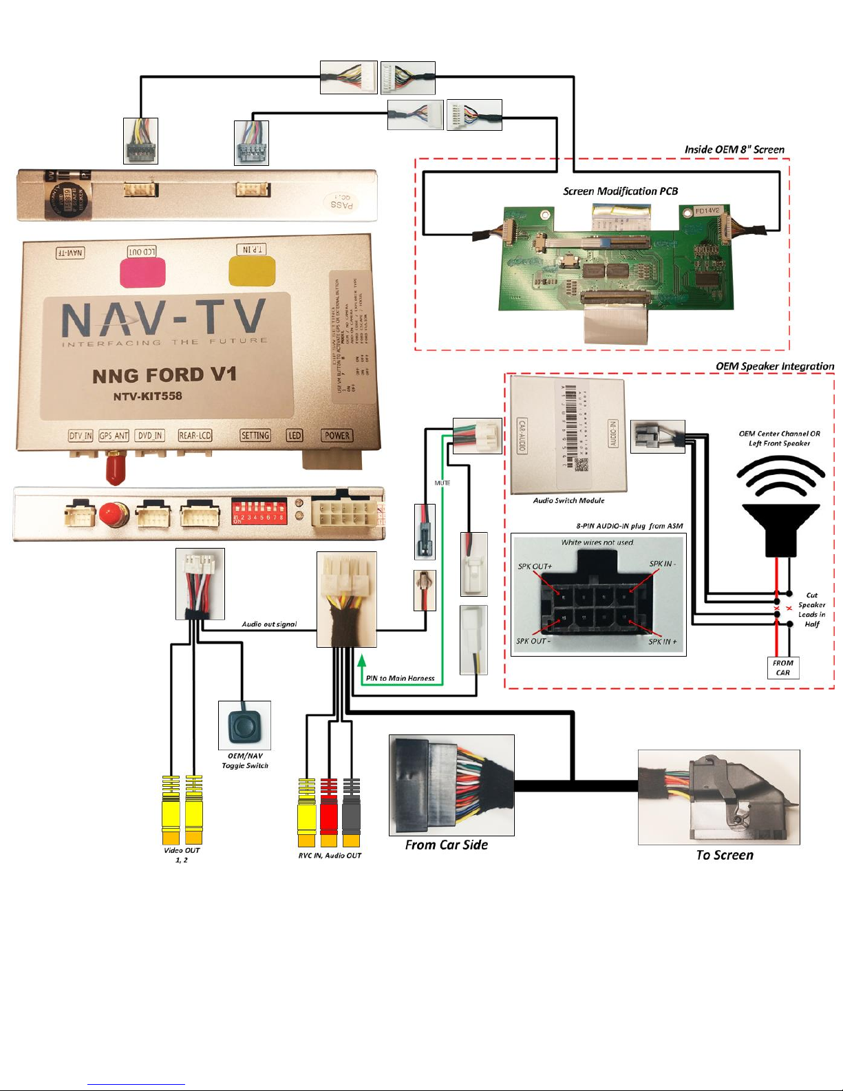
NNG-FORD V1 Wiring Diagram
Page 16

Ford Audio Integration
Components for audio integration:
1. GPS Audio Box
2. Wiring (FD-AUDSPK-02)
3. Wiring (AUD-6PIN-01)
4. Main Harness (same harness used in main install)
5. Rear-LCD (connected to GPS box from main install)
Steps:
1. Connect both FD-AUDSPK-02 and AUD-6PIN-01 to GPS Audio Box
2. Connect white, 2-PIN power plug to power from main Interface harness 2-PIN power
3. Insert green wire with pin to Main Harness (See figure 1)
Figure 1 Figure 1a
4. Connect 2-pin speaker plug to Rear-LCD speaker plug
5. Locate the dash center speaker. Note: If this car is not equipped with a center dash speaker, locate
the Front-LEFT driver speaker leads, heading into driver's front door. Wire colors are typically White
and White/Brown. Test wires before using!
6. AUD-6PIN-01 has 6wires, split to 2 black connectors. The WHITE wires are NOT used.
a. Cut the pair of signal leads from the OEM center channel speaker in HALF.
b. The FEMALE 4-PIN black plug is sound OUTPUT to Speaker (connect +
and -). Gray/Black: - and Gray: +.
c. The MALE 4-PIN black plug is sound INPUT from Car (connect + and -).
Gray/Black: - and Gray: +.
** Normally, radio audio will by-pass audio box. When GPS talks, audio box
will mute factory audio output and provide GPS audio to the dash speaker. **
insert pin here
green wire from
FD_AUDSPK-02
8-PIN black audio I/O pinout from Audio Box:
Page 14
Page 17
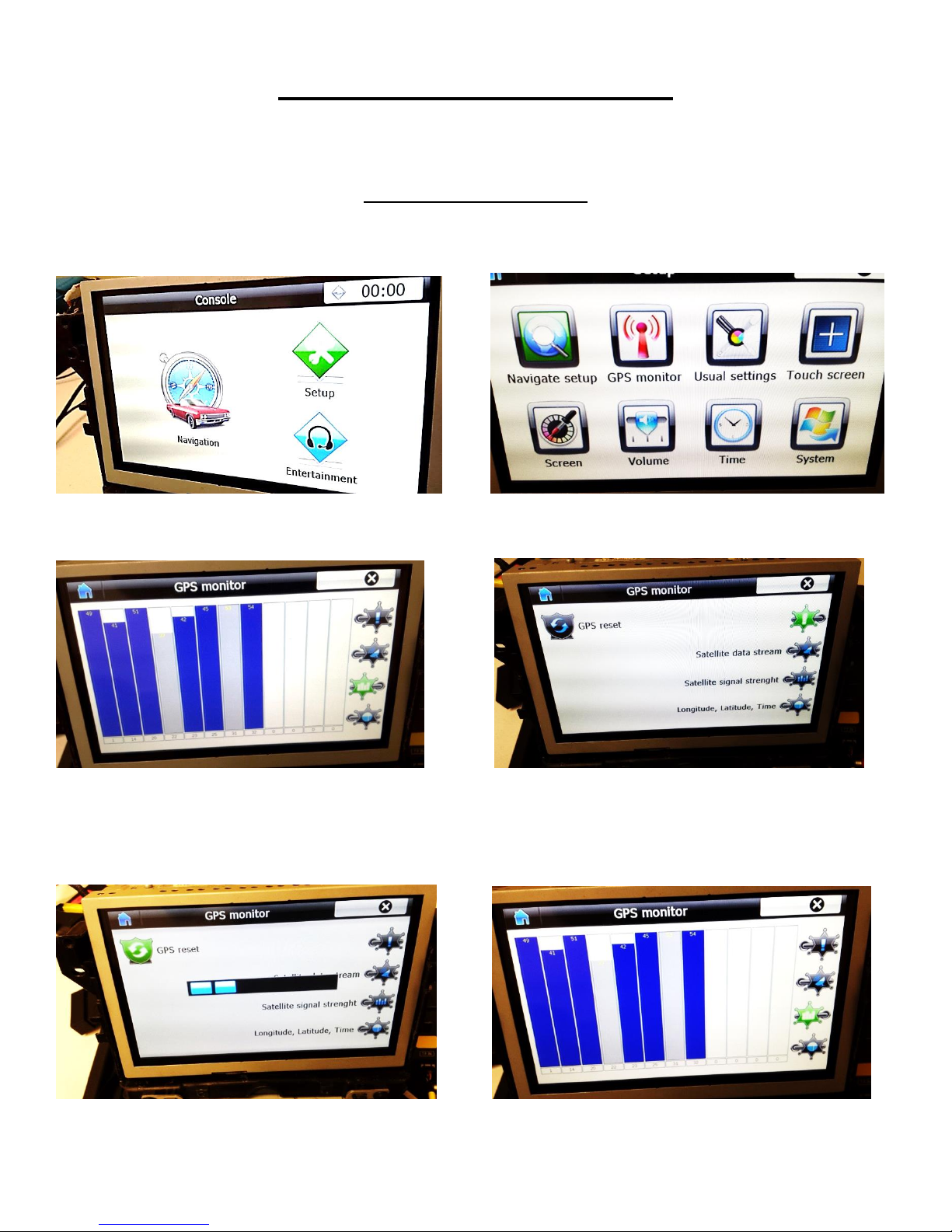
WEAK /NO GPS SIGNAL?
Tips to Improve GPS Antenna Signal if vehicle equipped Metallized Windshield*
“GPS MONITOR Tools”
Exit IGO MAP by press SHUT DOWN BUTTON
Console> SETUP GPS MONITOR
Locate the Antenna with minimum 5 bars in dark blue or Gray bar
(Always suggest mounting the GPS antenna on the roof)
Press “!” icon to reset GPS signal and change the Antenna position
Table of contents
Other NNG Car Navigation System manuals


