Nobels MF-2 User manual
Owners Manual - MIDI Foot Controller MF-2
OWNERS
MANUAL
KTA -040223

Owners Manual - MIDI Foot Controller MF-2
22
22
2
INDEX
1 Introduction and concept
1.1 Welcome . . . . . . . . . . . . . . . . . . . . . . . . . . . . . . . . . . . . . . . . . . . . . . . . . . . . . . . . . 3
1.2 Conventions . . . . . . . . . . . . . . . . . . . . . . . . . . . . . . . . . . . . . . . . . . . . . . . . . . . . . . 3
2 Views
2.1 Frontview . . . . . . . . . . . . . . . . . . . . . . . . . . . . . . . . . . . . . . . . . . . . . . . . . . . . . . . . 4
2.2 Backview . . . . . . . . . . . . . . . . . . . . . . . . . . . . . . . . . . . . . . . . . . . . . . . . . . . . . . . . . 4
3 Main features
3.1 128 programs . . . . . . . . . . . . . . . . . . . . . . . . . . . . . . . . . . . . . . . . . . . . . . . . . . . . . 5
3.2 Outputs / midi transmit channel . . . . . . . . . . . . . . . . . . . . . . . . . . . . . . . . . . . . . . . 5
3.3 MIDI bank select . . . . . . . . . . . . . . . . . . . . . . . . . . . . . . . . . . . . . . . . . . . . . . . . . . . 5
3.4 MIDI program change . . . . . . . . . . . . . . . . . . . . . . . . . . . . . . . . . . . . . . . . . . . . . . 5
3.5 MIDI volume . . . . . . . . . . . . . . . . . . . . . . . . . . . . . . . . . . . . . . . . . . . . . . . . . . . . . . 5
3.6 Switches . . . . . . . . . . . . . . . . . . . . . . . . . . . . . . . . . . . . . . . . . . . . . . . . . . . . . . . . . 5
3.7 Touch mode . . . . . . . . . . . . . . . . . . . . . . . . . . . . . . . . . . . . . . . . . . . . . . . . . . . . . . . 5
3.8 Fade mode . . . . . . . . . . . . . . . . . . . . . . . . . . . . . . . . . . . . . . . . . . . . . . . . . . . . . . . . 5
3.9 MIDI receive channel . . . . . . . . . . . . . . . . . . . . . . . . . . . . . . . . . . . . . . . . . . . . . . . 5
3.10 Economy . . . . . . . . . . . . . . . . . . . . . . . . . . . . . . . . . . . . . . . . . . . . . . . . . . . . . . . . . 5
3.11 MIDI controller . . . . . . . . . . . . . . . . . . . . . . . . . . . . . . . . . . . . . . . . . . . . . . . . . . . . 6
3.12 Special functions (PowerUp) . . . . . . . . . . . . . . . . . . . . . . . . . . . . . . . . . . . . . . . . . 6
4 Power on
4.1 Connecting a power supply . . . . . . . . . . . . . . . . . . . . . . . . . . . . . . . . . . . . . . . . . . . 6
4.2 Using batteries . . . . . . . . . . . . . . . . . . . . . . . . . . . . . . . . . . . . . . . . . . . . . . . . . . . . 6
4.3 Phantom power . . . . . . . . . . . . . . . . . . . . . . . . . . . . . . . . . . . . . . . . . . . . . . . . . . . . 6
4.4 Backup power . . . . . . . . . . . . . . . . . . . . . . . . . . . . . . . . . . . . . . . . . . . . . . . . . . . . . 6
5 Modes
5.1 Quick start . . . . . . . . . . . . . . . . . . . . . . . . . . . . . . . . . . . . . . . . . . . . . . . . . . . . . . . . 7
5.2 Connect to the switches . . . . . . . . . . . . . . . . . . . . . . . . . . . . . . . . . . . . . . . . . . . . . 7
5.3 Connect expression pedals . . . . . . . . . . . . . . . . . . . . . . . . . . . . . . . . . . . . . . . . . . . 7
5.4 Bank mode . . . . . . . . . . . . . . . . . . . . . . . . . . . . . . . . . . . . . . . . . . . . . . . . . . . . . . . 7
5.5 Direct mode . . . . . . . . . . . . . . . . . . . . . . . . . . . . . . . . . . . . . . . . . . . . . . . . . . . . . . . 7
6 Edit mode
6.1 Memory protection . . . . . . . . . . . . . . . . . . . . . . . . . . . . . . . . . . . . . . . . . . . . . . . . . 8
6.2 Program select . . . . . . . . . . . . . . . . . . . . . . . . . . . . . . . . . . . . . . . . . . . . . . . . . . . . . 8
6.3 Save a program . . . . . . . . . . . . . . . . . . . . . . . . . . . . . . . . . . . . . . . . . . . . . . . . . . . . 8
6.4 Copy a program . . . . . . . . . . . . . . . . . . . . . . . . . . . . . . . . . . . . . . . . . . . . . . . . . . . . 8
6.5 Output select . . . . . . . . . . . . . . . . . . . . . . . . . . . . . . . . . . . . . . . . . . . . . . . . . . . . . . 8
6.6 Selecting MIDI program changes . . . . . . . . . . . . . . . . . . . . . . . . . . . . . . . . . . . . . . 8
6.7 Bank select . . . . . . . . . . . . . . . . . . . . . . . . . . . . . . . . . . . . . . . . . . . . . . . . . . . . . . . 8
6.8 Using MIDI volume level . . . . . . . . . . . . . . . . . . . . . . . . . . . . . . . . . . . . . . . . . . . . 9
6.9 Activate the switches (relays) . . . . . . . . . . . . . . . . . . . . . . . . . . . . . . . . . . . . . . . . . 9
6.10 Using the touch mode . . . . . . . . . . . . . . . . . . . . . . . . . . . . . . . . . . . . . . . . . . . . . . . 9
6.11 Using the fade mode . . . . . . . . . . . . . . . . . . . . . . . . . . . . . . . . . . . . . . . . . . . . . . . . 9
7 Setupmode
7.1 Output / MIDI transmit channel . . . . . . . . . . . . . . . . . . . . . . . . . . . . . . . . . . . . . . 10
7.2 MIDI receive channel . . . . . . . . . . . . . . . . . . . . . . . . . . . . . . . . . . . . . . . . . . . . . . 10
7.3 Economy configuration . . . . . . . . . . . . . . . . . . . . . . . . . . . . . . . . . . . . . . . . . . . . . 10
7.4 Setup the MIDI volume . . . . . . . . . . . . . . . . . . . . . . . . . . . . . . . . . . . . . . . . . . . . . 10
7.5 Switches configuration . . . . . . . . . . . . . . . . . . . . . . . . . . . . . . . . . . . . . . . . . . . . . 11
7.6 MIDI bank select setup . . . . . . . . . . . . . . . . . . . . . . . . . . . . . . . . . . . . . . . . . . . . . 11
7.7 Controller configuration . . . . . . . . . . . . . . . . . . . . . . . . . . . . . . . . . . . . . . . . . . . . 12
7.8 Controller functions . . . . . . . . . . . . . . . . . . . . . . . . . . . . . . . . . . . . . . . . . . . . . . . . 12
7.9 Controller curves . . . . . . . . . . . . . . . . . . . . . . . . . . . . . . . . . . . . . . . . . . . . . . . . . . 12
7.10 Description of the curves . . . . . . . . . . . . . . . . . . . . . . . . . . . . . . . . . . . . . . . . . . . 12
8 Special functions
8.1 MIDI dump (transmit) . . . . . . . . . . . . . . . . . . . . . . . . . . . . . . . . . . . . . . . . . . . . . . 13
8.2 MIDI dump (receive) . . . . . . . . . . . . . . . . . . . . . . . . . . . . . . . . . . . . . . . . . . . . . . . 13
8.3 Funny note mode . . . . . . . . . . . . . . . . . . . . . . . . . . . . . . . . . . . . . . . . . . . . . . . . . . 13
8.4 Test mode . . . . . . . . . . . . . . . . . . . . . . . . . . . . . . . . . . . . . . . . . . . . . . . . . . . . . . . 13
8.5 Initialise (factory setup) . . . . . . . . . . . . . . . . . . . . . . . . . . . . . . . . . . . . . . . . . . . . . 14
8.6 List of the global adjustments . . . . . . . . . . . . . . . . . . . . . . . . . . . . . . . . . . . . . . . . 14
8.7 List of the local adjustments . . . . . . . . . . . . . . . . . . . . . . . . . . . . . . . . . . . . . . . . . 14
8.8 MIDI controller list . . . . . . . . . . . . . . . . . . . . . . . . . . . . . . . . . . . . . . . . . . . . . . . . 14
8.9 Technical information . . . . . . . . . . . . . . . . . . . . . . . . . . . . . . . . . . . . . . . . . . . . . . 14
Caution
1 Before using the MF-2 read this Owners' Manual thoroughly.
2 Do not open the unit! No user serviceable parts inside.
3 Use only power supplies as specified in the technical information.
4 Do not use in dusty, wet or extremely hot environments.
5 This device may interfere with radio and TV reception. Do not use in the vicinity of such
receivers.
6 Contact qualified service personnel immediately if:
* The housing is damaged and the unit does not work properly
* Small items or liquids of any kind penetrate the unit
* in the event of any other problem
7 The MF-2 contains a lithium battery. To avoid explosion do not expose the battery to extremes
of heat or light.
(c) Nobels Electronics
All rights reserved - Author: Kai Tachibana

Owners Manual - MIDI Foot Controller MF-2 33
33
3
1.1 WELCOME TO THE NOBELS MF-2
Thank you for choosing the MF-2. This unit will help you make music more easily than ever
before. We've made sure that each MF-2 is set up in the factory for immediate use, so if you
are anxious to begin using your new unit straight away, GO AHEAD! When you need to know
the myriad possibilities in more detail, come back to this manual - you'll find that your
MF-2 can help you in hundreds of ways.
- WHAT IS MIDI?
MIDI stands for Musical Instrumental Digital Interface, a universal standard allowing
different instruments to communicate with each other. As well as note messages, MIDI can
be used to adjust Program Control (ie sound selection), Volume, Expression, Aftertouch etc.
Because MIDI operates on channels (just like a TV set), up to sixteen different devices to be
independently controlled - the MF-2 is your remote controller.
- WHY DO I NEED THE MF-2?
As you acquire more MIDI-compatible units, your MIDI setup, either on stage or in the studio,
can become very complex. Each device has a set of buttons operating each of its functions,
and in the end you could spend more time pressing buttons than playing music. The MF-2
will make your setup easy to manage, acting as the central controller for all these functions
on all your MIDI devices.
- WHAT WILL MY MF-2 DO FOR ME?
Once you start working with your MF-2, you will wonder how you ever managed without it.
Use the MF-2's 10 pedals to send MIDI Bank and Program changes, to select switches, outputs
and controllers, and to control a variety of other functions including Touch and Fade. Plug
in up to four foot switches and four expression pedals to control different MIDI devices. You
can even control functions like Channel Select or Reverb On/Off on non-MIDI units like
amplifiers etc. With the MF-2 you have access to your entire MIDI setup at the touch of a
pedal.
Please enjoy using your MF-2. Full instructions for programming and special functions are
given in detail inside this manual.
1 INTRODUCTION AND CONCEPT
1.2 CONVENTIONS
There are two menus EDIT and SETUP. In the EDIT mode you can change local parameters for the 128
programs. In the SETUP mode you can adjust values for the overall (=global) functions.
The functions of the EDIT mode are left next the corresponding footswitch printed in bold letters.
Beneath, in italic letters, the description for the SETUP mode.
Functions and options are adjusted with the SELECT-key. All values can be set either with the UP/DOWN
footswitches or with the 0..9 footswitches.
All menus are left with the ENTER key. Local changes for one program should be saved with the STORE
key. After reaching the end of the menus the display will show the changes with a flashing "t"
If you do not save, all changes will be lost. All changes are direct which means if you change the changes
(e.g.: midi volume) are right now herable! Destructive or special functions, like the factory setup, are
recalled by doing a special procedure (=Power Up), to prevent accidently killing your saved settings!
If you have any further questions, suggestions or other comments please contact your local
dealer or write to us direct at:
Nobels Electronics e.K.
Barnerstrasse 42
22765 Hamburg
Germany

Owners Manual - MIDI Foot Controller MF-2
44
44
4
2 VIEWS
2.2 BACK VIEW
(6) Switch ouputs 1-4
(7) Memory protect switch (ON/OFF)
(8) MIDI In/Out jacks
(9) Power supply jack (9~12V DC/0.5A)
(10) Power switch (ON/OFF/PHANTOM)
(11) Expression pedal outputs 1-4
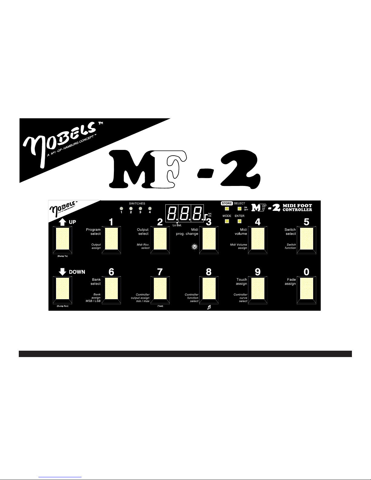
2.1 FRONT VIEW
(1) Display (3-digit LED)
(2) Programming keys: Store-Select-Mode-Enter
(3) Footswitches (numbered 1-9, 0)
(4) UP/DOWN footswitches
(5) LED indicators for Switches 1-4

Owners Manual - MIDI Foot Controller MF-2 55
55
5
3 MAIN FEATURES
3.1 128 PROGRAMS
The MF-2 contains 128 Programs. Each program stores:
- 16 MIDI BANK SELECT (Incl. General MIDI Banks!)
- 16 MIDI PROGRAM CHANGES
- 16 MIDI VOLUMES
- 4 SWITCH settings
- 1 FADE function, incl. FADE TIME
- 1 TOUCH function
3.2 OUTPUTS / MIDI TRANSMIT CHANNEL
The MF-2 has 16 OUTPUTS. Each of the 16 OUTPUTS can be assigned to the MIDI TRANSMIT
CHANNELS and is also switchable ON/OFF.
Advantage: Each MIDI TRANSMIT CHANNEL of the connected MIDI device can
be easiely changed!
Possible values: 1-16, OFF
Default: OUTPUT 1-16 = MIDI TRANSMIT CHANNEL 1-16
OUTPUT 1 = ON (activ)
OUTPUT 2-16 = OFF (inactiv)
3.3 MIDI BANK SELECT
You can choose up to 16 different BANK SELECTS for the MIDI PROGRAM CHANGE. Needed values
(MSB, LSB) can be adjusted separately.
This is a little complicated, but there is no way to make it easier. Please refer to the
Midi implementation charts of the connected midi devices!
Main function of the BANK SELECT:
- CONTROLLER 0 (MSB) sends a value from 0 to 127.
- CONTROLLER 32 (LSB) sends a value from 0 to 127.
- The following MIDI PROGRAM CHANGE will change PROGRAM and BANK.
Default: BANK SELECTS 0..15 = 0
3.4 MIDI PROGRAM CHANGE
Each of the activated OUTPUT can send one MIDI PROGRAM CHANGE.
Possible values:
Program Changes = 1-128 (true MIDI = 0-127)
Off = Sends nothing!
Start = Sends MIDI START (Sequencer, Drummachine)
Stop = Sends MIDI STOP (Sequencer, Drummachine)
Continue = Sends MIDI CONTINUE (Sequencer, Drummachine)
Reset = Sends MIDI RESET (Keyboard, Soundmodule)
Default: MIDI PROGRAM CHANGE = MF-2 PROGRAM number.
3.5 MIDI VOLUME
On each OUTPUT you can send one MIDI VOLUME (=Controller 7). Only if the MIDI VOLUME is
switched to ON and also is selected for the corresponding OUTPUTS!
Possible values: 0-127 and OFF
Default: VOLUME = 64; In the SETUP = OFF
3.6 SWITCHES
Each program stores a combination of the four outputs for the switches. The main function of each
switch must be adjusted in the SETUP.
Default: All relays = OFF
SWITCH 1,2 = Pos. latched switch SWITCH 3,4 = Pos. unlatched switch / Time=50
3.7 TOUCH MODE
You can mark each of the 128 programs to be a TOUCH function.(BANK mode only!) Touch means:
- footswitch [0..9] is pressed: The MF-2 changes to the selected program.
- footswitch [0..9] is released: The MF-2 changes to the previously selected program.
Default: TOUCH = OFF
3.8 FADE MODE
On each OUTPUT you can send a FADE function. You have 2 kinds of FADE:
FADE-IN: The MIDI VOLUME runs from "0" up to the values of the MIDI VOLUME set
in the actual program.
(= Smooth increasing of the volume)
FADE-OUT: The MIDI VOLUME runs from the values of the MIDI VOLUME set in the actual
program down to 0.
(= Smooth decreasing of the volume)
Default: FADE-IN 1..128 = OFF, t= 50
3.9 MIDI RECEIVE CHANNEL
The MF-2 can be switched with any midi device connected to the MF-2's MIDI IN jack. First the
DISPLAY shows the received MIDI PROGRAMM CHANGE but after a moment it shows the previously
manually selected PROGRAM (=flashing). (E.g.: BANK mode: The MF-2 leaves not the selected bank!)
Possible values: 1-16, OFF, OMNI
OFF = receives no MIDI PROGRAM CHANGES
OMNI = receives all MIDI PROGRAM CHANGES
Default: MIDI RECEIVE CHANNEL = 1
3.10 ECONOMY
The MF-2 has four different steps of brightness for the display. You will waiste less energy if you choose
the darkest step. The "automatic": If you activate the automatic the MF-2 will be switched to the darkest
when the power goes down. Additionall the left marked point "Lo-Bat." starts flashing.
Possible values: 1-4
Default: ECONOMY = 1 (Max. Brightness); Automatic = OFF
Owners Manual - MIDI Foot Controller MF-2
66
66
6
3.11 MIDI CONTROLLER
Each of the connected expression pedals can be assigned to the functions as follows:
.1 CONTROLLER SELECT
Select the desired expression pedal.
.2 CONTROLLER OUTPUT
Select the OUTPUT to be used by the selected Controller.
Possible values: CONTROLLER OUTPUT = 1..16, OFF
.3 CONTROLLER MIN/MAX:
Select the lower and upper range.
Possible values: MIN = 0-126, MAX = 1-127
Default: MIN = 0, MAX = 127
.4 CONTROLLER FUNCTION:
Select the desired MIDI CONTROLLER NUMBER.
A detailled list is located at the end of this manual!
Possible values: CONTROLLER NUMBER = 0-127
Default: EXP.-PEDAL 1 = Contr.# 7, EXP.-PEDAL 2 = Contr.# 8,
EXP.-PEDAL 3 = Contr.# 11, EXP.-PEDAL 4 = Contr.# 6
.5 CONTROLLER CURVE:
Select one of the ten predefined curves.
Possible values: CURVE: Linear, A2, A3, C2, C3 (each forward and backward)
Default: CURVE: Linear - forward
3.12 SPECIAL FUNCTIONS (POWERUP)
We use a procedure to achieve special functions: Switch the unit off; while switching the unit on, hold
a specified key. (=PowerUp)
.1 MIDI DUMP TRANSMIT
Transmit all or one programs to an external midi device (MIDI-DISK, SEQUENCER,) or to
another MF-2.
.2 MIDI DUMP RECEIVE
Receive all or one of the 128 previously saved programs from an external midi device (MIDI-
DISC, SEQUENCER,) or from another MF-2.
.3 FUNNY NOTE MODE (MF-2 as keyboard)
Send 12 MIDI notes (C~Bb) on 10 selectable octaves.
.4 TEST MODE
Check the MF-2 with the built in TEST mode.
.5 VERSION
Shows the actual software version number.
.6 FACTORY SETUP
Warning - Overwrites internal data. Your own settings will be restored with the
default values!
You need a specified "PASSWORD" to activate this function (see page 14; chapter 8.5)
4 POWER ON
4.1 CONNECTING A POWER SUPPLY
Connect a stabilised power supply (9V DC up to 12V DC) to the Power jack (5), located at the back of
the unit. The MF-2 uses a new economical powerregulation, which saves up to 33% of energie.
.1 Set the POWER Switch (1) to position ON.
.2 Connect a standard midi cable to the MIDI-OUT jack.
.3 The other end of the cable has to be connected to the MIDI-IN jack of the "receiver".
.4 The unit is ready to go!.
4.2 USING BATTERIES
.1 Insert 6 batteries to the battery compartment, located at the bottom of the unit.
.2 Simply open the screw of the battery cover with a screwdriver or a coin.
To save more batterielife you can switch to a lower step of brightness of the display. (*see page 10, chapter
7.3 "ECONOMY CONFIGURATION"). You can activate the built in AUTOMATIC to automatically lower
the brightness when the power of the batteries goes down. If the left Displaypoint (Lo Bat.) flashes, the
batteries should be exchanged, to prevent malfunction of the unit.
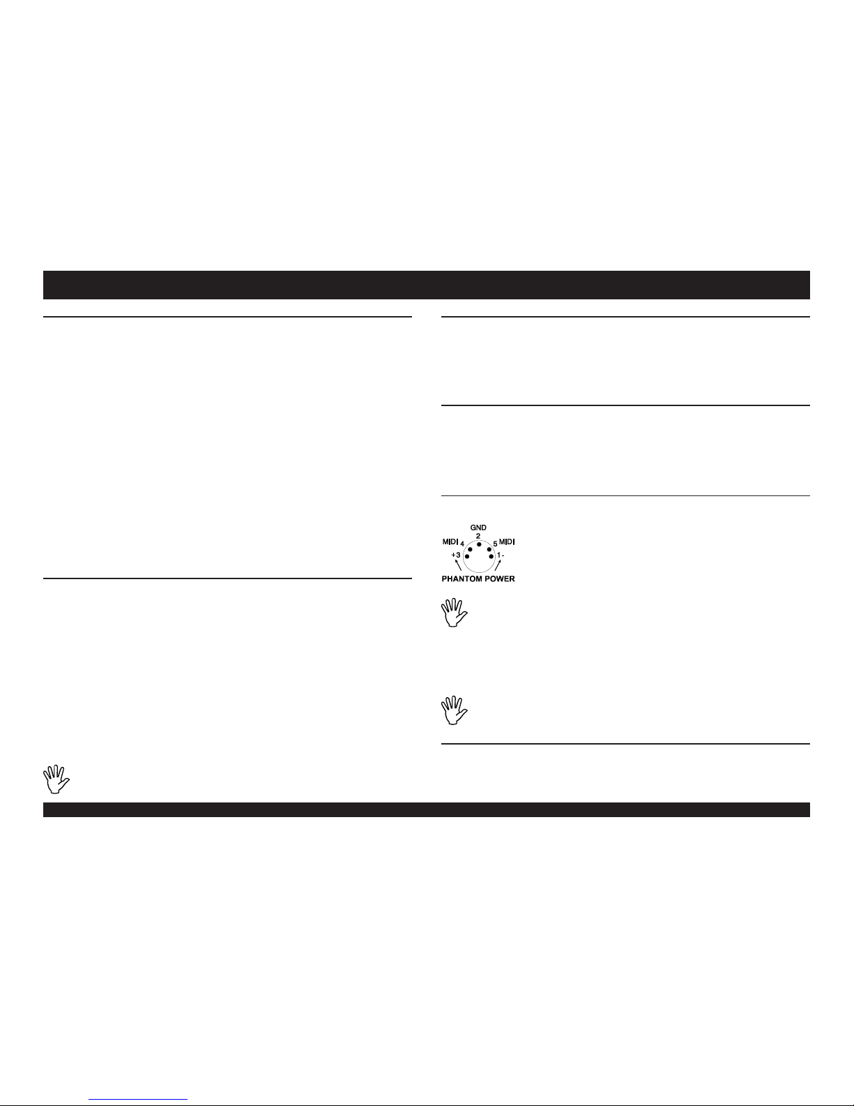
4.3 PHANTOM POWER
Some other manufacturer are also using the MIDI jacks to distribute power from one unit to another
(Phantom power). This is easy to handle and you can probably save nerves, time and
money which means you need one power adaptor less. The required power may
now be supplied from your MIDI effect or keyboard. For this make sure the
connected power supply is strong enough to supply all connected units!
The idea of the polarity and the connection is described in the ELECTRONIC
MUSICIAN issued #12/89. Some other manufacturer are also using this idea!
Please check the polarity and voltage before using phantom power to
prevent any damages of the connected units.
.1 Supply another unit with phantom power:
You can supply another unit with phantom power by using the MIDI IN (6) jack of the MF-
2.
The MF-2 now supplies the connected device.
.2 Supply the MF-2 from another unit
Connect the MIDI IN jack of the other midi unit (=transmitter) to the MIDI OUT jack (7) of
the MF-2 (=receiver). To switch the MF-2 on set the POWER switch to position "PHANTOM".
Attention: Make sure you use (buy) a 5-wired MIDI-cable!
4.4 BACKUP POWER
The MF-2 uses an internal lithium battery to hold the internal data (memory) during power off. The life
is approx. 5~7 years. The MF-2 permanently checks it state. If the backup battery is down, the middle
point of the 3 digit LED DISPLAY will flash. Save all data (MIDI DUMP TRANSMIT) and let the battery
be exchanged by an authorized service center. (see technical information; page 14, chapter 8.9)
CONNECTIONMAIN FEATURES

Owners Manual - MIDI Foot Controller MF-2 77
77
7
5.1 QUICK START
Normally the MF-2 is right now ready to work. No further settings are neccessary to use it as a standard
MIDI footcontroller:
.1 Depending of the selected mode (bank - direct) you can send out MIDI PROGRAM CHANGES
.2 Each of the 128 programs are equal with MIDI PROGRAM CHANGES 1-128.
Attention: Some midi devices are displaying TRUEMIDI 0-127. For this you have
to know that 0=1, 1=2, ..127=128!
.3 The default MIDI TRANSMIT CHANNEL is 1.
5.2 CONNECT TO THE SWITCHES
The MF-2 is able to remote control up to four non-MIDI units with the internal relays (SWITCHES
1..4). For example: Channelselect, Reverb, Tremolo can be controlled by the MF-2. Each of the
internal relays is not connected to the other nor to the MF-2. This prevents problems with humnoise.
.1 Connect the units with a standard cable to one of the jacks SWITCHES 1..4.
If needed you can use the SWITCHES
1..4 to switch between two sources. For
that you must use a stereo cable. See
the diagram for more information how
to do that:
5.3 CONNECT EXPRESSION PEDALS
Attention: If the MEMORY PROTECT switch is set to "ON", you cannot enter the
EDIT or SETUP mode!
.1 To change data you must set the MEMORY PROTECT switch to "OFF".
.2 Up to four expression pedals can be used with the MF-2, to send MIDI CONTROLLER data
t o
the connected midi devices.
The function of the MIDI CONTROLLER numbers are listed at the end of this
manual!
(See page 14; chapter 8.8)
5 MODES
You can choose between two different modes to use the MF-2 as a MIDI footcontroller: The BANK mode
or the DIRECT mode.
5.5 BANK MODE
The bank mode should be used to change between programs with a single step on a footswitch 0-9.
.1 Press the MODE key until the DISPLAY shows:
.2 After pressing the "ENTER" *1 key the BANK MODE is activ. (*1 or footswitch!)
.3 Use the footswitches "UP" or "DOWN" to select the banks 0-12.
If one of the footswitches "UP" or "DOWN" is hold for a longer period the bank will be changed
faster.
.4 Press any footswitch 0..9 to select the requested program. After that the MF-2 sends out the
midi information of the selected program.
.5 Each further step on a footswitch 0..9 selects another program and recalls it immediately.
Note: Because there are a limit number of possible MIDI programs 1..128, bank
number 0 and 13 have one program less.
This means program number "0" and "129" are not accessable!
5.6 DIRECT MODE
In this mode you can activate a program by selecting the numbers with the footswitches 0..9 and
activate it by pressing the "UP" or "DOWN" footswitch.
.1 Press the MODE key until the DISPLAY shows:
.2 After pressing the "ENTER" key the DIRECT MODE is activ.
.3 The MF-2 shows the last accessed PROGRAM.
.4 Select the requested PROGRAM numbers with the footswitches 0..9 and activate it with one
of the footswitch "UP" or "DOWN".
BANK / DIRECTQUICK START
Each further input "moves" the numbers to the left. Impossible
numbers (lower 1, greater 128) are automatically corrected.
If the requested number is achieved, press one of the
footswitches UP/DOWN to send the program. The right digit
flashes until you send out the program!
Each further step of the footswtich UP or DOWN adds or
subtract 1 and sends it out immediately. After PROGRAM 128
PROGRAM 1 will be selected.
If one of the footswitches "UP" or "DOWN" is hold for a longer
period the programs will be changed faster.
If the requested numbers is achieved, press one of the
footswitches UP/DOWN to send the program. The right digit
flashes until you send out the program!
Sample:
e.g footswitch 1
than footswitch 2
and footswitch 5

Owners Manual - MIDI Foot Controller MF-2
88
88
8
6.1 MEMORY PROTECTION
To protect the internal memory of the MF-2 against overwriting you can set the MEMORY PROTECT
switch (7) (located on the back) to "ON".
.1 The memory ist protected in position "ON":
You are not able to choose the EDIT or SETUP mode.
.2 The memory ist unprotected in position "OFF":
You are able to choose the EDIT or SETUP mode.
To make any changes in the EDIT mode the MEMORY PROTECT (7) switch must
be in position "OFF".
6.2 PROGRAM SELECT
You are about to edit the program which was last selected. But it is also possible to change programs
in the EDIT mode:
.1 Press the MODE key until the DISPLAY shows:
Select a PROGRAM (Values: 1..128)
.2 Press footswitch 1 (PROGRAM SELECT).
.3 Enter the requested program with the footswitches 0..9, UP/DOWN
.4 Press the ENTER key.
6.3 SAVE A PROGRAM
Unsaved changes are shown in the DISPLAY with the flashing "t" of "Edt". (Except FADE- and TOUCH
mode!)
.1 Press the STORE key.
.2 The DISPLAY flashes with the actual PROGRAM number.
.3 If desired, select a different PROGRAM with the footswitches 0..9, UP/DOWN.
.4 Press the STORE key again.
.5 The DISPLAY shows:
.6 The actual PROGRAM was saved on the shown PROGRAM place.
If you do not save the actual changes of a PROGRAM all changes will be lost when
the EDIT mode is left or another PROGRAM is selected!
6.4 COPY A PROGRAM
.1 In the EDIT mode: Select the PROGRAM to be copiied.
.2 Press the STORE key.
.3 The DISPLAY flashes with the actual PROGRAM number.
.4 Select a different PROGRAM with the footswitches 0..9, UP/DOWN.
.5 Press the STORE key again.
.6 The DISPLAY shows:
.7 The actual PROGRAM was saved on the shown PROGRAM place.
6.5 OUTPUT SELECT
An OUTPUT refers to a MIDI TRANSMIT CHANNEL selected in the SETUP mode. Unused OUTPUTS
should be set to "OFF" in the setup.
.1 SELECT EDIT:
OUTPUT SELECT (Values: 1..16)
.2 Press footswitch 2.
The DISPLAY shows: (Output 1).
.3 Enter the requested OUTPUT number with the footswitches 0..9, UP, DOWN.
.4 Press the ENTER key.
6.6 SELECTING MIDI PROGRAM CHANGES
Note: MIDI PROGRAM CHANGES are switching connected MIDI devices to the corresponding
PROGRAMS. For this you must set the correct MIDI TRANSMIT CHANNEL of the "transmitter" to
the same MIDI RECEIVE CHANNEL of the "receiver". (see page 10, chapter 7.2)
.1 SELECET EDIT:
SELECET A MIDI PROGRAM CHANGE:
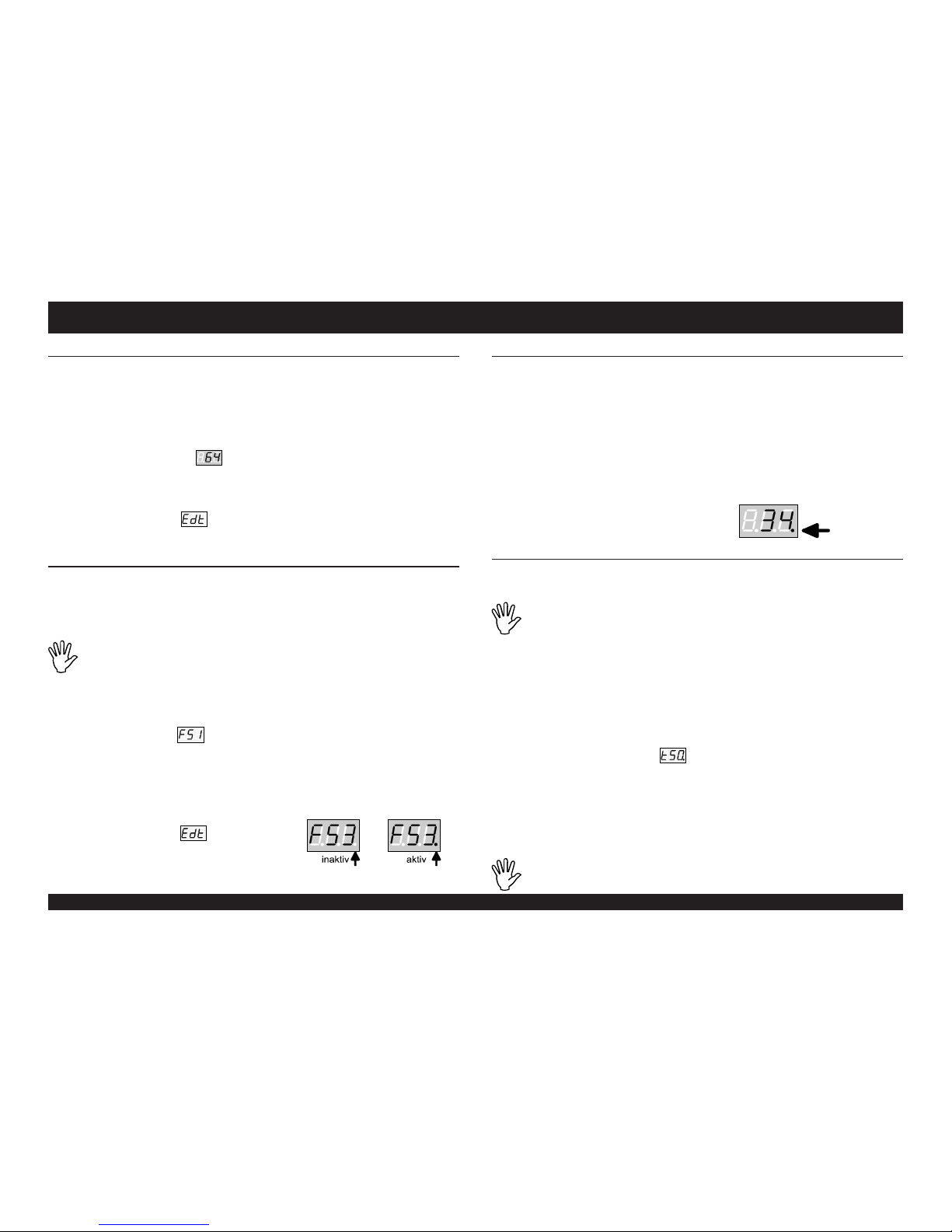
.2 Press footswitch 3.
The DISPLAY shows e.g. program:
.3 Enter the MIDI PROGRAM CHANGE with the
footswitches 0..9, UP, DOWN.
The special functions Off, Start, Stop, Continue, and
Reset are only accessable with the footswitches UP/
DOWN!
They are located between PROGRAM 128 and 1
.4 Press the ENTER key.
.5 The DISPLAY shows: The flashing "t" shows up the changes you made!
!!! Do not forget to save the changes!
6.7 BANK SELECT
.1 SELECT EDIT:
BANK SELECT (Values: 0..15)
.2 Press footswitch 6 (BANK SELECT).
.3 The DISPLAY shows the actual BANK number. E.g. bank "0" =
.4 Select one of the 16 banks by pressing the footswitches 0..9, UP/DOWN.
.5 Press the ENTER key.
.6 The DISPLAY shows: The flashing "t" shows up the changes you made!
!!! Do not forget to save the changes!
6 EDIT MODE OUTPUT / PROGRAM CHANGE / BANK SELECTMEMORY PROTECT / COPY / PROGRAMSELECT
Owners Manual - MIDI Foot Controller MF-2 99
99
9
6 EDIT MODE
6.8 USING MIDI VOLUME LEVEL
Together with the MIDI PROGRAM CHANGES you can also send MIDI VOLUME information.
Requirements: 1) The correct OUTPUT in the MIDI VOLUME ASSIGN must be switched to "ON".
2) The connected midi device must be support MIDI VOLUMES!
.1 SELECT EDIT:
SELECT A MIDI VOLUME (Values: 0..127, OFF).
.2 Press footswitch 4 (MIDI VOLUME).
The DISPLAY shows e.g.: (Midi volume 64).
.3 Enter the requested MIDI VOLUME with the footswitches 0..9, UP, DOWN.
.4 OFF is located between 127 and 0. For this you have to use the UP or DOWN footswitch.
.5 Press the ENTER key.
.6 The DISPLAY shows: The flashing "t" shows up the changes you made!
!!! Do not forget to save the changes!
6.9 ACTIVATE THE SWITCHES (RELAYS)
The operation mode for each SWITCH (relay) must be predefined for proper function. Each of the
internal relays is not connected to the other nor to the MF-2. This prevents problems with humnoise.
The main function (latched switch, unlatched switch) has to be defined in the SETUP mode.
(See page 11, chapter7.5)
Warning: Do not use a higher current of max. 5 ampere. Higher current may
damage the relays. For safety reasons it is not allowed to use voltages higher than
40 volts for switching - You will risc your life!
.1 SELECT EDIT:
SELECT A SWITCH (Values: 1..4).
.2 Press footswitch 5 (SWITCH SELECT).
The DISPLAY shows:
.3 Enter the requested SWITCH with the footswitches 1..4, UP, DOWN.
.4 Press the ENTER key.
.5 Press the SELECT key to activate or deactivate the corresponding SWITCH.
The corresponding SWITCHES LED and the right point in the DISPLAY are lighting up:
SWITCH = activ.
.6 Press the ENTER key.
.7 The DISPLAY shows:
The flashing "t" shows up the changes you made!
!!! Do not forget to save the changes!
6.10 USING THE TOUCH MODE
The TOUCH mode is a special function which only works in the BANK mode. If you press a footswitch
0..9 the selected PROGRAM will be send. After releasing the footswitch 0..9 the previous PROGRAM
will be send again. This means the selected PROGRAM is activated as long as you hold the footswitch!
(Also perfect for MIDI functions Start, Stop, Continue and Reset!)
.1 SELECT EDIT:
.2 Press footswitch 9 (TOUCH ASSIGN)
.3 The DISPLAY shows the actual PROGRAM number
.4 Enter the PROGRAM to be assigned with the footswitches 0..9, UP, DOWN.
TOUCH ASSIGN (Values: ON, OFF)
.5 With the SELECT key you can switch the TOUCH function for the shown PROGRAM number
on and off.:
On = right point in the DISPLAY is on.
Off = right point in the DISPLAY is off.
.6 Press the ENTER key to leave the TOUCH ASSIGN
6.11 USING THE FADE MODE
The FADE mode is a special function for fading the MIDI VOLUME in or out. If a FADE PROGRAM
is selected the MIDI VOLUME will be changed from the actual saved MIDI VOLUME down to 0 or
from 0 up to the actual saved MIDI VOLUME. The fadetime is adjustable from 0.1 ~ 9.9 seconds.
Attention: The FADE function only works if the MIDI VOLUME is activated and
not set to "OFF". (And of course the MIDI TRANSMIT CHANNEL is correct!)
.1 SELECT EDIT:
.2 Press footswitch 0 (TOUCH ASSIGN).
.3 The DISPLAY shows the actual PROGRAM number
.4 Enter the PROGRAM to be assigned with the footswitches 0..9, UP, DOWN.
FADE ASSIGN (Values: ON, OFF)
.5 With the SELECT key you can switch the FADE function for the shown PROGRAM number
.6 Press the ENTER key.
SET THE FADE TIME (Value: 1..99)
.7 The DISPLAY shows e.g. time:
.8 Enter the requested TIME with the footswitches 0..9, UP, DOWN.
SET THE FADE FUNCTION (Value: IN, OUT)
.9 With the SELECT key you can switch the FADE function for the shown PROGRAM number
FADE-IN = right point in the DISPLAY is on..
FADE-OUT = right point in the DISPLAY is off.
.10 Press the ENTER key.
.11 Press the ENTER key to leave the FADE ASSIGN.
Note: The middle point in the DISPLAY lights up while the FADE mode is running!
TOUCH / FADEVOLUME / SWITCH

Owners Manual - MIDI Foot Controller MF-2
1010
1010
10
7 SETUP MODE
OUTPUT / TRANSMIT CHANNEL / RECEIVE CHANNEL
7.1 OUTPUT / MIDI TRANSMIT CHANNEL
The MF-2 is able to send on all 16 MIDI TRANSMIT CHANNELS simultaneously. If you need less you
better deactivate unused MIDI TRANSMIT CHANNELS in the SETUP. For each OUTPUT you can
assign a separate MIDI TRANSMIT CHANNEL. There may be a malfunction if two or more active
OUTPUTS are set to the same MIDI TRANSMIT CHANNEL.
.1 SELECT SETUP:
.2 Press the MODE key until the DISPLAY shows:
OUTPUT ASSIGN (Values: 1..16)
.3 Press footswitch 1 (OUTPUT ASSIGN).
The DISPLAY shows: (OUTPUT 1 = ON)
.4 Enter the requested OUTPUT with the footswitches 0..9, UP, DOWN.
.5 The SELECT key switches the OUTPUT on- or off (On = right point lights up).
.6 Press the ENTER key.
ASSIGN A MIDI TRANSMIT CHANNEL (Values: 1..16)
The DISPLAY shows: (TRANSMIT CHANNEL 1 = ON)
.7 Enter the requested TRANSMIT CHANNEL with the footswitches 0..9, UP, DOWN.
.8 Press the ENTER key.
!!! Changes of the SETUP are saved after pressing the ENTER key!
7.2 MIDI RECEIVE CHANNEL
You have to setup the MIDI RECEIVE CHANNEL to communicate with
other MIDI devices. The MIDI CHANNEL must be the same like setting
up your television set to desired frequencies or channels to receive sound
and pictures of the requested programs!
But for MIDI you also can select an OMNI mode: receives on all channels!
.1 SELECT SETUP:
MIDI RECEIVE CHANNEL (Values: 1..16, OMNI, OFF)
.2 Press footswitch 2 drücken (MIDI RCV SELECT).
.3 The DISPLAY shows: (MIDI RECEIVE CHANNEL = 1).
.4 Enter the requested CHANNEL with the footswitches 0..9, UP, DOWN.
.5 OMNI and OFF is located between 127 and 0. For this you have to use the UP or DOWN
footswitch.
.6 Press the ENTER key.
!!! Changes of the SETUP are saved after pressing the ENTER key!
ECONOMY / MIDI VOLUME
7.3 ECONOMY CONFIGURATION
The brightness of the DISPLAY is adjustable in four steps! 1 = bright; 2..4 = less bright . A switchable
"automatic" switches the DISPLAY to "4" if the power (batteries) goes down.
.1 SELECT SETUP:
ECONOMY SETUP (Values: 1..4)
.2 Press footswitch 3 ( )
.3 The DISPLAY shows: (ECONOMY 1)
.4 Enter the requested BRIGHTNESS with the footswitches 0..9, UP, DOWN.
Changes are immediately visible!
AUTOMATIC:
.5 The SELECT key switches the AUTOMATIC on or off.
On = right point lights up.
Off = right point is off.
.6 Press the ENTER key.
!!! Changes of the SETUP are saved after pressing the ENTER key!
7.4 SETUP THE MIDI VOLUME
The MIDI VOLUME function can be assigned for each OUTPUT. Only on active OUTPUTS the MF-
2 will send MIDI VOLUME data!
.1 SELECT SETUP:
MIDI VOLUME ASSIGN (Values: 1..16, OFF)
.2 Press footswitch 4 (MIDI VOLUME ASSIGN)
.3 The DISPLAY shows: (OUTPUT 1 = ON)
.4 Enter the requested OUTPUT with the footswitches 0..9, UP, DOWN.
.5 The SELECT key switches the OUTPUT for the MIDI VOLUME function on- or off.
(On = right point lights up)
.6 Press the ENTER key.
!!! Changes of the SETUP are saved after pressing the ENTER key!
Owners Manual - MIDI Foot Controller MF-2 1111
1111
11
7 SETUP MODE
SWITCH CONFIGURATION BANK SELECT
7.5 SWITCH CONFIGURATION
There are commonly four different kinds of switches:
- positive switch (latched) : 1x switching = ON, 1x switching = OFF
- negative switch (latched) : 1x switching = OFF, 1x switching = ON
- positive switch (unlatched) : press = ON, release = OFF
- negative switch (unlatched) : press = OFF, release = ON
Note: You can adjust the time for the unlatched switches between 1..128. Devices with built in computer
normally needs a longer time for switching. You have to increase the default value of "40" (=120ms)
if the connected device is not switching correctly. If possibble try to choose the shortest time: 1
(=15ms). The highest value can be 128 (=400ms).
.1 SELECT SETUP
SELECT A SWITCH (Values: 1..4)
.2 press footswitch 5 (SWITCH FUNCTION).
The DISPLAY shows:
.3 Enter the requested SWITCH with the footswitches 1..4, UP, DOWN.
.4 Press the ENTER key.
Select the SWITCH function (Values: 1..4)
The DISPLAY shows one of the four functions e.g.:
1) pos. latched switch,
2) neg. latched switch,
3) pos. unlatched switch,
4) neg. unlatched switch
.5 Enter the requested SWITCH FUNCTION with the footswitches 1..4, UP, DOWN.
.6 Press the ENTER key.
.7 If you selected a latched switch the input is finished.
.8 If you selected a unlatched switch:
Adjust the SWITCH TIME (Values: 1..128)
.6 Enter the requested TIME with the footswitches 0..9, UP, DOWN.
.7 Press the ENTER key.
!!! Changes of the SETUP are saved after pressing the ENTER key!
7.6 MIDI BANK SELECT SETUP
The BANK SELECT is defined of two MIDI CONTROLLER data: Controller 0 sends the MSB,
Controller 32 sends the LSB. The values for MSB/LSB can be adjusted separately for each OUTPUTS.
You can configure 16 different BANK SELECTS for each OUTPUT 1..16!
.1 SELECT SETUP
SELECT OUTPUT (Values: 1..16)
.2 Press footswitch 6 (BANK ASSIGN)
The DISPLAY shows: (OUTPUT 1)
.3 Enter the requested OUTPUT with the footswitches 0..9, UP, DOWN.
.4 Press the ENTER key.
Select a BANK number (Values: 0..15)
The DISPLAY shows: (BANK number 0).
.5 Enter the requested BANKwith the footswitches 0..9, UP, DOWN.
.6 Press the ENTER key.
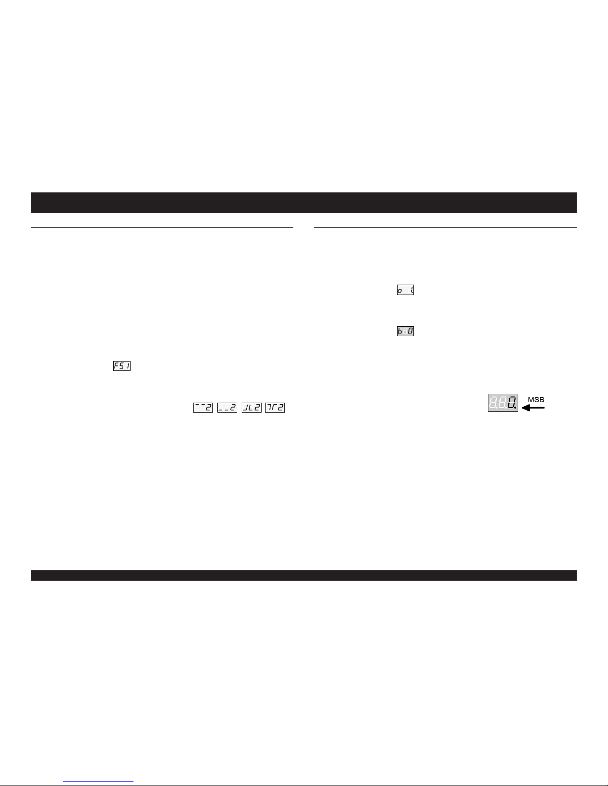
Select the MSB (Values: 0..127, OFF)
Note: If you select OFF no BANK SELECTS will be send! (=Controller 0 and 32)
.7 Enter the requested MSB value with the footswitches 0..9, UP, DOWN.
For identification only:
The right point lights up for the MSB value!
.8 Press the ENTER key.
Select the LSB (Values: 0..127)
.9 Enter the requested LSB value with the footswitches 0..9, UP, DOWN.
.10 Press the ENTER key.
!!! Changes of the SETUP are saved after pressing the ENTER key!
Please refer to the owners manuals of your midi devices for more information about midi
bank selects!
Here is a sample:
OFF = MSB = OFF, LSB = nnn
For soundmodule Korg*1) 05R/W:
PROGRAM 0-99 = MSB = 0 , LSB = 0, PRG = 0-99
GM-BANK 0-127 = MSB = 56 , LSB = 0, PRG = 0-127
GM-PROGRAM No.: 129 = MSB = 63 , LSB = 0, PRG = 0
GM-PROGRAM No.: 130 = MSB = 63 , LSB = 0, PRG = 10
*1) Korg is a registered trademark.

Owners Manual - MIDI Foot Controller MF-2
1212
1212
12
7.7 CONTROLLER CONFIGURATION (EXPRESSION PEDALS)
The four CONTROLLER 1..4 for the expression pedals are independend of the 128 PROGRAMS.
.1 SELECT SETUP
Select a CONTROLLER (Values: 1..4)
.2 Press footswitch 7 (CONTROLLER OUTPUT ASSIGN, MIN./MAX.)
The DISPLAY shows: (CONTROLLER 1).
.3 Enter the requested CONTROLLER with the footswitches 1..4, UP, DOWN.
.4 Press the ENTER key.
Assign the OUTPUTS (Values: 1..16, OFF)
The DISPLAY shows e.g. for OUTPUT 1: or (=OFF)
.5 Enter the requested OUTPUT with the footswitches 0..9, UP, DOWN.
.6 OFF is located between 16 and 1. For this you have to use the UP or DOWN footswitch.
.7 Use the SELECT key to switch the OUTPUT on or off.
(On = right point lights up.)
.8 Press the ENTER key.
Select MIN. LIMIT (lower) (Values: 0..126)
.9 Enter the requested value for MIN. LIMIT with the footswitches 0..9, UP, DOWN.
For identification only: The right point lights up for the MIN. LIMIT value!
.10 Press the ENTER key.
Select MAX. LIMIT (upper) (Values: 1..127)
.11 Enter the requested value for MAX. LIMIT with the footswitches 0..9, UP, DOWN.
.12 Press the ENTER key.
NOTE: The MIN. LIMIT is always greater than the MAX- Limit; the MAX. LIMIT
is always lower than the MIN. LIMIT!
ATTENTION: The internal autocorrection lets you save possible values only!
7.8 CONTROLLER FUNCTION
.1 SELECT SETUP
Select a CONTROLLER FUNCTION (Values: 1..4)
.2 Press footswitch 8 (CONTROLLER FUNCTION SELECT).
The DISPLAY shows: (CONTROLLER 1).
.3 Enter the requested CONTROLLER with the footswitches 1..4, UP, DOWN.
.4 Press the ENTER key.
Assign the CONTROLLER NUMBER (Values: 0..127)
.5 The Display shows the actual CONTROLLER NUMBER. (see page 14, chapter 8.8)
.6 Enter the requested CONTROLLER NUMBER with the footswitches 0..9, UP, DOWN.
.7 Press the ENTER key.
!!! Changes of the SETUP are saved after pressing the ENTER key!
7 SETUP MODE
CONTROLLER CONFIGURATION CONTROLLER CONFIGURATION
7.9 CONTROLLER CURVES
Some expression pedals are curious; the way you move the pedal is not optimal. This is a bad
conversion between the acoustic and the sensitivity of your ear or the technical values of your
expression pedal did not matches the requirements of the connected keyboard. To solve this known
problems you can choose between 5 predefined curves listed in the diagram beneath. Each of these
curves are invertable that you have a total of 10 different curves.
.1 SELECT SETUP
Select a CONTROLLER (Values: 1..4)
.2 Press footswitch 9 (CONTROLLER FUNCTION SELECT).
The DISPLAY shows: (CONTROLLER 1).
.3 Enter the requested CONTROLLER with the footswitches 1..4, UP, DOWN.
.4 Press the ENTER key.
Select a CURVE (Values: 0..9)
The DISPLAY shows: (CURVE 1).
.5 Enter the requested CURVE with the footswitches 0..9, UP, DOWN.
.6 Press the ENTER key.
!!! Changes of the SETUP are saved after pressing the ENTER key!
7.10 DESCRIPTION OF THE CURVES:
Cu0 = Linear, forward
Cu1 = Linear, backward
Cu2 = A2, forward
Cu3 = A2, backward
Cu4 = A3, forward
Cu5 = A3, backward
Cu6 = C2, forward
Cu7 = C2, backward
Cu8 = C3, forward
Cu9 = C3, backward
Controller Curves
Controller Value
V
O
L
U
M
E

Owners Manual - MIDI Foot Controller MF-2 1313
1313
13
8 SPECIAL FUNCTIONS
MIDI DUMP FUNNY NOTE MODE / TEST MODE
You can dump the internal programs of the MF-2 to or from an external device.
8.1 MIDI DUMP (TRANSMIT)
.1 Connect to an external device
An external device can be a Sequencer, MIDI-Recorder, or any other which is able to record MIDI data.
This is very useful to save the internal data in case of accidentially loose of data. For this connect a
MIDI cable between MF-2 MIDI OUT and the MIDI IN jack of the external device.
.2 SELECT POWER UP:
.3 Switch the MF-2 off.
.4 While switching the MF-2 on hold footswitch "UP".
Select the MIDI DUMP TRANSMIT (Values: ALL, 1..128)
.5 The DISPLAY shows:
.6 Enter the requested function with the footswitches 0..9, UP, DOWN.
"ALL" sends all 128 programs; 1..128 sends one of the 128 PROGRAMS only!
.7 Start recording with the sequencer or similar. (ext. device!).
.8 Press the ENTER key to send the data to the sequencer.
.9 The DISPLAY shows the process of the transmitting. (=000..031)
.10 After transmitting the data the DISPLAY shows:
.11 Switch the MF-2 off. Ready!
8.2 MIDI DUMP (RECEIVE)
.1 Connect an external device
Connect a MIDI cable between MF-2 MIDI IN and MIDI OUT jack of the other MIDI device.
.2 SELECT POWER UP:
.3 Switch the MF-2 off.
.4 While switching the MF-2 on hold footswitch "DOWN".
MIDI DUMP RECEIVE
.5 The DISPLAY shows:
.6 The MF-2 is idle until it receives the correct data!
NOTE: Unknown or strange data should never been send to the MF-2. In some
circumstances the internal data can be overwritten with junk.
.7 After receiving the data the DISPLAY shows:
.8 Switch the MF-2 off.
8.3 FUNNY NOTE MODE
The (just for fun) built in function of the FUNNY NOTE MODE in our previous model MF-1 was really
a success! Thanks to all! Therefore we have it in the MF-2 too! The FUNNY NOTE MODE enables you
to sends 12 MIDI notes (C~Bb; 10 octaves) to a connected keyboard.
.1 SELECT POWER UP:
.2 Switch the MF-2 off.
.3 While switching the MF-2 on hold footswitch "8".
Select the OUTPUTS (Values: 1..16)
.4 The DISPLAY shows:
.5 Enter the requested OUTPUT with the footswitches 0..9, UP, DOWN.
.6 Press the ENTER key.
Choose an OCTAVE (Values: 0..9)
.7 The DISPLAY shows: (Octave 5)
.8 Select the requested OCTAVE with the SELECT and ENTER key.
Use the footswitches 0..9, UP/DOWN to send MIDI NOTES on the selected octave.
You can set the octave with the SELECT and STORE key!
Have fun!
.9 Switch the MF-2 off to finish the FUNNY NOTE MODE.
8.4 TEST MODE
.1 SELECT POWER UP:
.2 Switch the MF-2 off.
.3 While switching the MF-2 on hold footswitch "7".
.2 DISPLAY test
Press any footswitch.
.3 KEY test
Hit / move all keys: Up, 1..5, Down, 6..0.
Store, Select, Enter, Mode, Memory Protect.
.4 Relais Test
Select a relay with footswitch 1..4.
Press the ENTER key to go to the next test.
.5 AD-converter test
Connect an expression pedal.
Select it with footswitch 1..4; move expression pedal. Values= 0-63.
Press the ENTER key to go to the next test.
.6 MIDI - IN / - OUT test
Connect a MIDI cable between IN and OUT jack.
If the test passes the MF-2 restarts with the DISPLAY test.
Display:
Owners Manual - MIDI Foot Controller MF-2
1414
1414
14
You can restore all or some parts (local, global) of the MF-2 to the factory defaults. (Initialize)
8.5 INITIALIZE (FACTORY SETUP)
WARNING:
All previously stored date will be lost!
.1 SELECT POWER UP:
.2 Switch the MF-2 off.
.3 While switching the MF-2 on hold footswitch "0".
.4 The DISPLAY shows:
.5 Enter the required password with the footswitches 0..9, UP, DOWN.
To prevent unwanted restoring it is a must to enter a specified PASSWORD:
"42" for complete initializing (SETUP and EDIT values)
"53" for SETUP initializing (Global values)
"64" for EDIT initializing (Local values = PROGRAM 1..128)
.7 Press the ENTER key.
.8 The DISPLAY shows: and after:
8.6 LIST OF THE GLOBAL CONFIGURATION
.1 MIDI RECEIVE CHANNEL = 1
.2 OUTPUT = MIDI TRANSMIT CHANNEL 1..16; OUTPUT 1 = ON, OUTPUT 2..16 =
OFF
.3 ECONOMY = 1 (max. brightness)
.4 MIDI VOLUME = OUTPUT 1..16 = OFF
.5 SWITCH SETUP
SWITCH 1..2 = pos. latched switch, SWITCH 3..4 = pos. unlatched switch / time = 40
.6 BANK SELECT = OUTPUT 1..16 = OFF
BANK SELECT 0..15 MSB = OFF, LSB = 0
.7 CONTROLLER 1..4 = OUTPUT 1 = ON, OUTPUT 2..16 = OFF, MIN= 0, MAX = 127
.8 CONTROLLER FUNCTION
Expression pedal 1 = MIDI CONTROLLER # 7 (volume)
Expression pedal 2 = MIDI CONTROLLER # 8 (balance)
Expression pedal 3 = MIDI CONTROLLER # 11 (expression controller)
Expression pedal 4 = MIDI CONTROLLER # 6 (data entry)
.9 CONTROLLER CURVE
CONTROLLER 1..4 = CURVE 0 (linear - forward)
8 SPECIAL FUNCTIONS
FACTORY SETUP LISTS
8.7 LIST OF THE LOACAL CONFIGURATION
.1 OUTPUT 1..16:
MIDI PROGRAM CHANGE = 1..128 (True MIDI= 0..127)
MIDI VOLUME = 64
BANK = 0
.2 SWITCH 1..4 = OFF
.3 TOUCH = OFF
.4 FADE = OFF, Time = 50
8.8 MIDI CONTROLLER LIST
0 Bank Select (MSB)
1 Modulation Wheel or Lever
2 Breath Controller
3 Undefined
4 Foot Controller
5 Portamento Time
6 Data Entry
7 Main Volume
8 Balance
9 Undefined
10 Pan
11 Expression Controller
12 to 15 Undefined
16 Joystick Y-Value
17 Joystick X-Value
18 to 19 General Purpose Controllers
20 to 31 Undefined
32 to 63 LSB for Values 0 to 31
64 Damper Pedal (Sustain)
65 Portamento
66 Sustenuto
67 Soft Pedal
68 Undefined
69 Hold 2
70 to 79 Undefined
80 to 83 General Purpose Controllers
84 to 90 Undefined
91 External Effects Depth
92 Tremolo Depth
93 Chorus Depth
94 Detune Depth
95 Phaser Depth
96 Data Increment
97 Data Increment
98 Non-Registered Parameter Number LSB
99 Non-Registered Parameter Number MSB
100Registered Parameter Number LSB
101Registered Parameter Number MSB
102to 120 Undefined
121to 127 Reserved for Channel Mode Messages
8.9 TECHNICHAL INFORMATION
Dimension : 430 x 170 x 73mm
Weight : ~2000g (Without batteries!)
Power : 9~12V DC / 500mA stabilized
Consumption : max. 400mA
Controls : 12 footswitches , 4 tact switches, 2 slide switches
Connection : Power, MIDI in, MIDI out, 4 x remote switches, 4 x expression pedals
Display : 3 digit LED Display, 4 x LED
Relays : max. 40V / 5 Ampere
Memory : 8Kbyte static RAM
Internal lithiumbattery : Type CR2032; approx. life: 5~7 years. The middle point (DISPLAY) lights
up when it should be replaced! Contact your service center!
Table of contents
Other Nobels Recording Equipment manuals


Popular Recording Equipment manuals by other brands


Yamaha
Yamaha E1010 operating manual

Details
Details Sonet installation instructions

Philips
Philips CDR760/05 Instructions for use

Peak
Peak PLIN-USB user manual

Enforcement Technology Group
Enforcement Technology Group 60113 operating manual

Endress+Hauser
Endress+Hauser Commubox FXA291 technical information