UWI-IQ manual (rev. 5.07.2019) Page 3/12
Description
Universal wireless interface UWI-IQ can serve either as a node of the ICAS
wireless IQ system with uCU-IQ control panel or two UWI-IQ units can be
used for wireless link, which is independent on IQ system.
The communication protocol is compatible with the ICAS IQ system. The
UWI-IQ is supposed to be powered from the device which is connected to
or from uPU-IQ. There are wide possibilities of user configurations
available, which allows to adapt the UWI-IQ to specific user application.
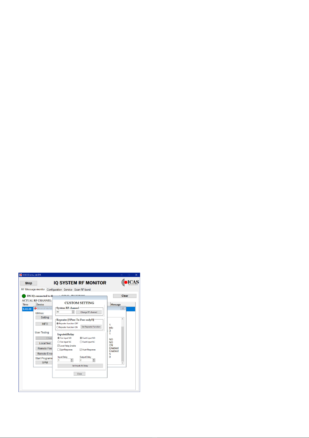
The configuration is designed as wireless and user friendly special PC
application - part of the RF monitor software tool, which serves for ICAS
wireless system configuration and monitoring.
Wireless link is able to secure transmission of two input signals from one
UWI-IQ unit by wireless to two relay outputs and loop option of the second
UWI-IQ unit, which are configured into a wireless link. (peer to peer
system configuration)
The UWI-IQ inputs are supposed to be connected to potential-free contacts
and can be configured as NC or NO which is possible to set for each input
individually.
( typically relay outputs of IRS-3 or control panels or open collector outputs
possibly). The corresponded alarm/fault message is sent after the contacts
connected to UWI inputs are switched on (NO config.) / switched off (NC
config.). After its releasing/ connecting is sent the corresponded stop alarm/
stop fault message then.
UWI-IQ allows to indicate power supply on by green LED, activity on
inputs and running pre-alarm (inputs delay) or outputs delay from the
remote alarm/failure message by yellow and red LEDs - the red LED
serves also for Test indication.
The next two LEDs serve for indication of received messages (remote
events) at the same time with relevant outputs activity.
Fire ALARM relay is activated after receiving of the fire alarm message -
the loop optional output will increase the current. The FAULT relay is
activated after receiving of the fault message.
It is possible to set in UWI-IQ configuration the outputs / relays response
also to local events and also it is possible to set delay of the output after
alarm/fault message receiving.
If a control panel wired loop is connected to the UWI-IQ loop terminal
instead of EOL resistor, the normal loop current flows through the UWI-IQ
in normal condition. There are available two different levels of the normal
loop current - corresponds to IMC-Mx panels or to IFP-2.32 panel. The
switch on position J3 on the UWI-IQ Terminal board serves for an easy
choice of the required normal loop current level.
The UWI-IQ will increase the loop current after the fire alarm message
receiving to the fire alarm level, for the connected control panel.
The fault is indicated by interruption of the loop after fault message
receiving - the loop current gets down and it will affect loop fault indication
on the connected control panel.
(Typically application - transmission of FIRE ALARM and FAULT signals
between two UWIs, - for example from remote IRS-3 aspiration detector
to a standard ICAS control unit - IMC-MD, IFP2.32 etc.)
The same kind of UWI-IQ model can serve either as wireless transmitter or
receiver or as a node of ICAS IQ system on the detector level.
UWI-IQ unit can serve also as an universal interface for ICAS IQ system
with uCU-IQ control panel(s). In this configuration the UWI-IQ unit
occupies one detector position in the system configuration.
There is an easy adjustable delay available for fire alarm and fault
messages. After appearing of alarm condition on an input, the message is
not sent immediately, but after a pre-alarm time. The alarm/fault is tested
repeatedly with period about 4 s and only after the specified number of
positive tests is reached, the corresponded message is transmitted.
The required pre-alarm period (input delay) is easy adjustable by user in
steps about 4s. The easy way to set is to use the RF-monitor and set the
required delay in the UWI-IQ configuration page.
The stop alarm/ stop fault messages are not delayed.
The UWI-IQ is able to send and receive both alarm and fault signals
sequentially. In case the both alarm and fault signal are received, the both
relays are activated and the alarm status has priority on the loop optional
output.
It is possible to set also an output delay, which is an adjustable delay
between receiving of the alarm or failure message and a correspondent
output activities. This delay is user adjustable from the UWI-IQ
configuration page of the RF - monitor.
Testing & Delay setting.
The UWI-IQ can be tested by the TEST button. It is possible to test the
radio-communication this way- short press of the test button evokes
transmitting of the Tests / Reset message depends on current UWI-IQ
status - normal / test mode.
The UWI-IQ gets from normal to test mode either by test button activity
or after receiving of the test message from another component in
wireless system configuration.
As soon as the Test mode is enabled, the outputs of the UWI-IQ unit
will follow its inputs, which allows to test the hardware easy. The
transmitting of alarm/failure messages is kept in the test mode too.
The test mode can be stopped by the Test button or by receiving of the
reset message.
Test mode will be reset automatically in about 3 minutes if any reset
message or button activity is not coming.
The response to the alarm/ fault events on UWI-IQ inputs can be
delayed. The delay of the correspondent message sending is determined
by number of input tests after the input signal level change from normal
to alarm / fault condition.
The response to the alarm/fault disappearing ( to the change of the
signal level to normal level ) is not delayed.
The default value of the delay is set to 2 (2 samples = 2 x 4s)
The delay ( number of samples) is possible to change or check by PC
with RF monitor software .
UWI-IQ allows an alternative set of a new input delay without PC
assistance by a long press of the Test button. For the new delay set
press the test button till appears the long yellow LED light and
following required number of red flashes .
Every red flash during this set up routine means an incrementing of
the number of signal samples between input change and message
sending (Increasing of the delay with next 4s.)
You can check the current delay easy by an intended shortage of an
UWI-IQ input and counting of flashes during the pre-alarm time.
The output delay is possible to set/change only from the RF-monitor ,
the default set is 0. If an output delay is set, the indication of the output
delay will start after alarm/fault message receive by double flash of red
or yellow LEDs (depends on received message F or E) with period
about 4s. After the output delay time-out the double flashes stopped and
UWI-IQ gets to the standard event indication and correspondent relay
and loop output is activated.
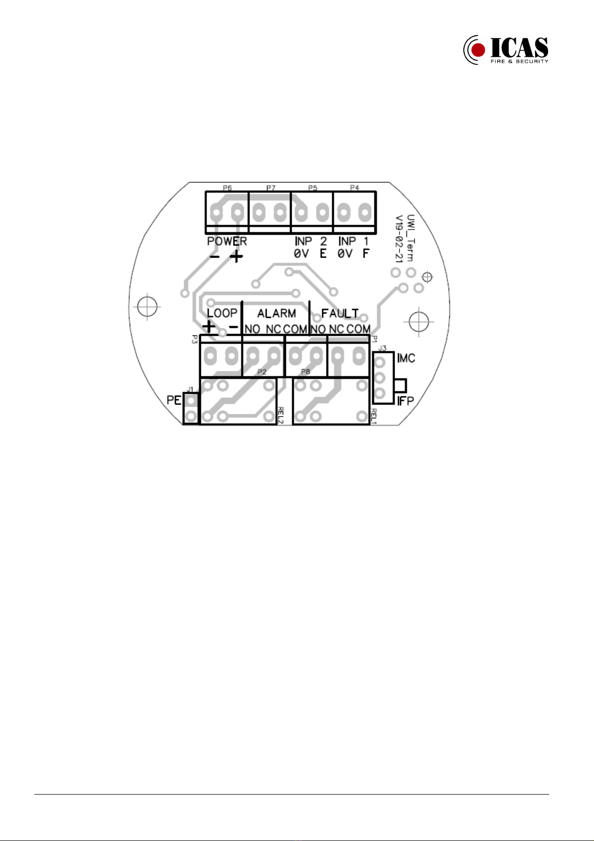
Terminal description:
There are two terminal lines at the UWI-IQ -Term board.
(The terminals are marked directly by their function - the numbers
used in this description are not on the PCB print)
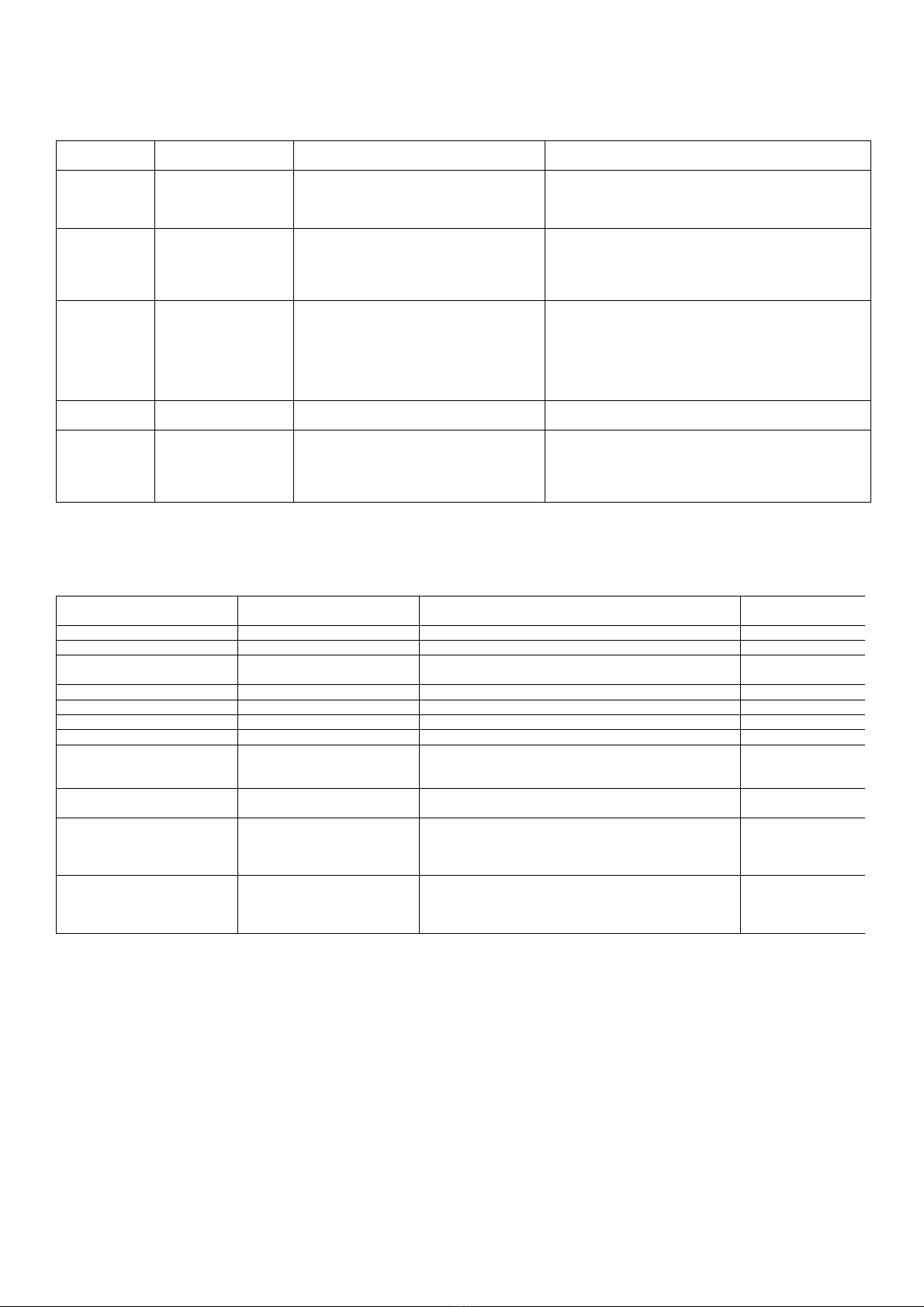
INPUT terminal line:
1 - POWER ( 0V - power supply input)
2 + POWER 9-12V DC - power supply input
3
4
5 INP 2 0V (Fault) signal input pot.free contact or 0V for
OC
6 INP 2 E (Fault) signal input potential free contact or
OC
7 INP 1 0V (Fire) signal input pot.free contact or 0V for
OC
8 INP 1 E (Fault) signal input potential free contact or
OC