Noble House Home Furnishings TRIANGULAR PERGOLA User manual
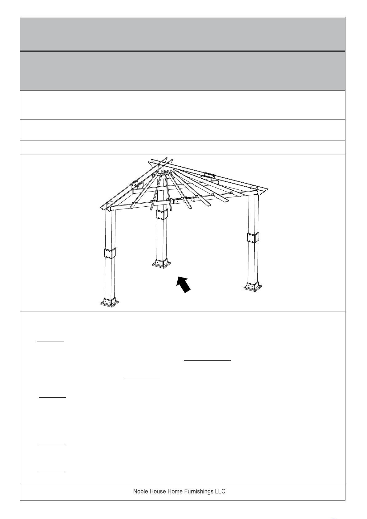
TRIANGULAR PERGOLA
Please look into the Corner Roof Support Joist package for all hardware.
CAUTION : IT IS RECOMMENDED THAT YOU :
1. ) DO NOT USE THE PERGOLA DURING INCLEMENT WEATHER.
2. ) ENSURE ALL CHILDREN ARE SUPERVISED, AT ALL TIMES, DURING USE OF PERGOLA.
3. ) UNATTENDED CHILDREN MUST NOT BE ALLOWED TO USE THIS PERGOLA.
4. ) DO NOT HANG ANY HEAVY OBJECT ONTO ANY PART OF THE PERGOLA.
5. ) USE STEP LADDERS ONLY TO ASSEMBLE THIS PERGOLA.
6. ) IN THE PROCESS OF ASSEMBLY, IF YOU SHOULD ACCIDENTALLY LOSE ANY HARDWARE,
DO NOT REPLACE WITH YOUR OWN HARDWARE.
7. ) IN THE PROCESS OF ASSEMBLY, IF YOU SHOULD ACCIDENTALLY DAMAGE THE WOOD,
DO NOT PROCEED WITH THE ASSEMBLY.
CAUTION: You must read this Assembly Instructions before you proceed.
Assembly Instructions
Note 1: Post Mounting Hardware is NOT included in this kit.
Please confirm with your local hardware store to determine the correct hardware.
Left
Front
Right
Rear
1 OF 46

2 OF 46
CAUTION :
1. ) It is highly recommended that you read and familiarise yourself with this Assembly Instructions
before you proceed to assemble this Pergola.
2. ) This Pergola consists of MANY PARTS. These Parts - would require your actions to
JOIN / CONNECT, to become Components. The Components will then be ASSEMBLED
to form the Pergola.
3. ) Team work - We recommend 4 to 5 adults partners and this assembly may require 3 to 4
hours to fully assemble the Pergola.
4. ) Before assembling, check all available parts and hardware are complete and intact.
5. ) Step Ladders are required at some stage in the Assembly Process. It is recommended
that you check the Serviceability and Condition of the Step Ladders before use.
6. ) Exercise Caution during and throughout the entire assembly process. This is especially
required during lifting of heavy or large parts and or the long Joists.
7. ) Do Exercise Safety at all times when using the Step Ladders and or Hammer when staking
the Garden Stakes into the ground.
8. ) We recommend you to SELECT your ideal location to set up the Pergola and that the entire
Pergola is assembled closest to this ideal location. By selecting your ideal location,
it would minimize moving about the Pergola upon partial and completion of assembly.
The assembly in your ideal location would minimize injury to you and or your partners, and
or damage(s) to the Pergola.
9. ) Upon selecting your ideal location, ensure the ground is firm, flat and even surface.
10. ) We recommend you to display and / or layout the parts / components in a "bundle manner"
as recommended here below. This would allow for quick and easy retrieval during the
assembly.
11. ) Ensure NO ONE other than those Partners should be allowed in the work-assembly area.

3 OF 46
MAINTENANCE INSTRUCTIONS:
1. Check all nuts and bolts monthly twice after Installation and tighten as required.
Note: Don’t overtight, which may lead to cracking of wood.
2. Inspect the wood parts monthly. Check for any sharp edges, lift in grains or splinters. If found, a
light sanding is necessary, followed by the application of sealant. It will prevent further splitting or
any other weather-related damages.
3. Replace any rusted bolts, nuts, and washers. If not, sand it and repaint using Non-leaded paint,
meeting the requirements of Title 16CFR Part 1303.
4. To increase the longevity of the wooden pergola, consider staining and sealing at least once a year.
Stain and sealant adds a layer of protection to the wood, protecting from UV rays and temperature
changes, and also helps to maintain the wood color.
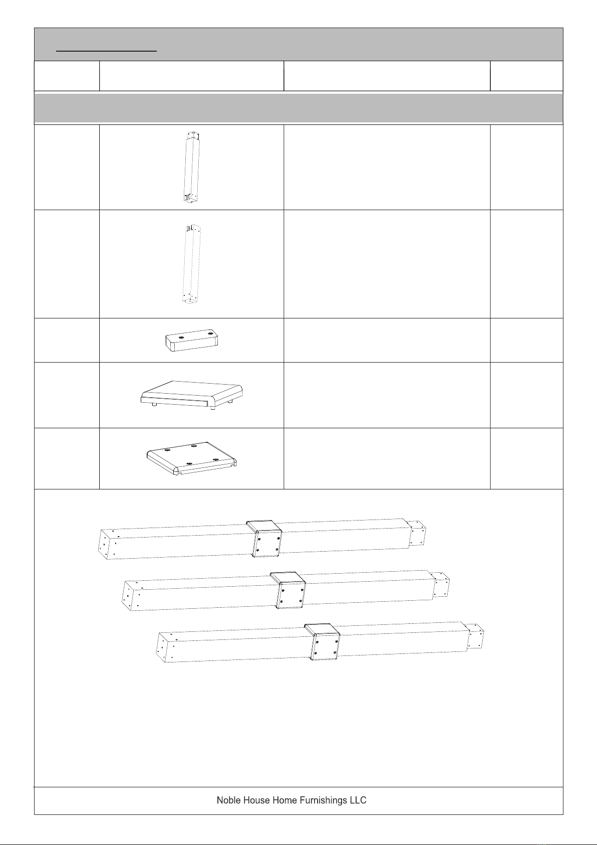
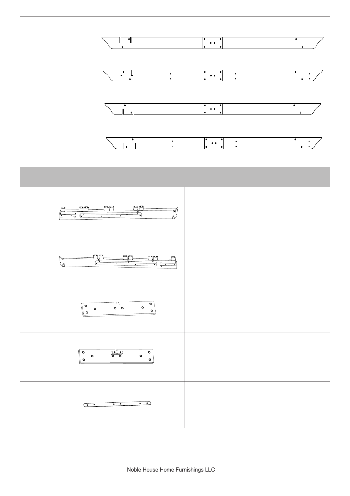
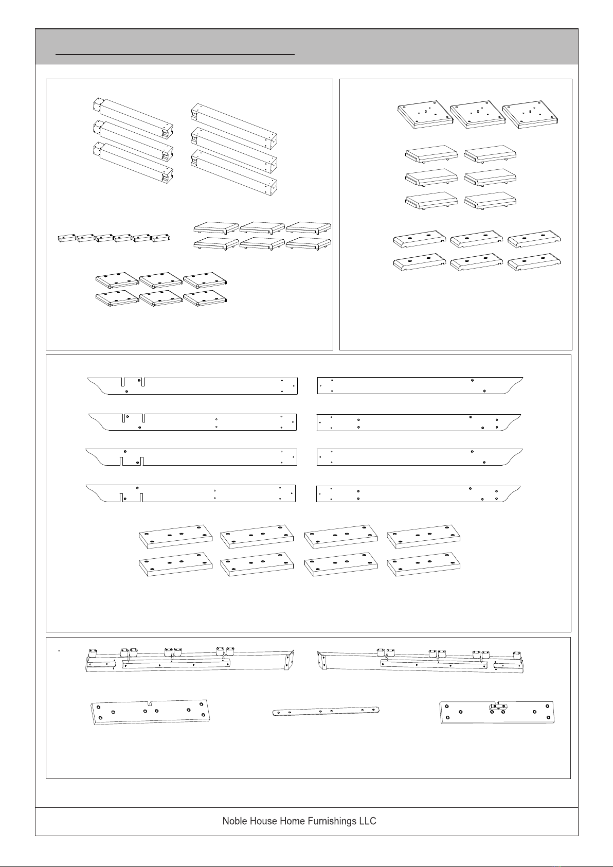
Parts List
A1 3
Upper Pillar
No. Picture Description Qty
A2
Lower Pillar
A3
A4
A5
Pillar Joint - Key
3
6
6
6
Pillar Mid Joinery - Anchor
Panel ( with 4 (four) pcs of
pre-attached wooden dowels )
Pillar Mid Joinery - Slide Panel
with Grooves
Note 2 : Upon completion of Bundle Part 1 assembly, you would have 3
( three ) pcs of Pillar.
Please ensure all Bolts and Screws are FULLY tighten after these are
assembled.
4 OF 46
Bundle I ) Parts of Pillars
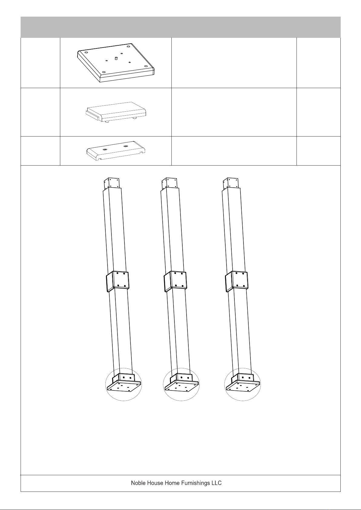
B1 3
Pillar Base : Foot Base
B2
Pillar Base : Foot Apron -
Anchor Panel with 4 (four)
pcs of pre-attached wooden
dowels)
B3 Pillar Base : Foot Apron -
Slide Panel
6
6
Bundle II ) Parts of Foot Base & Foot Aprons
Note 3 : Upon completion of Bundle Part II, you would have assembled all
3 ( three ) Pillars, complete with Foot Bases. These would look as above.
Please ensure all Bolts and Screws are FULLY tighten after these
are assembled.
5 OF 46
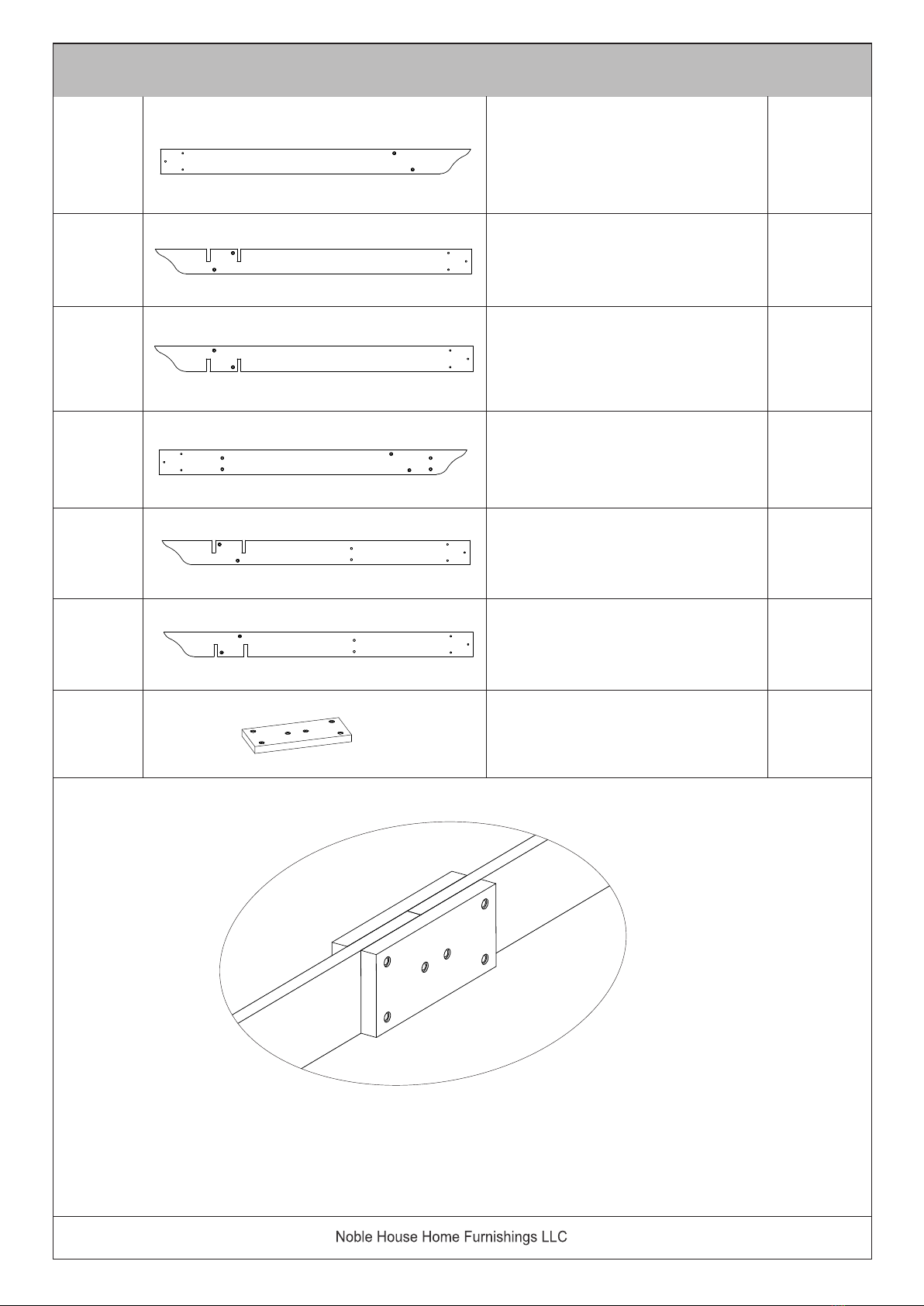
C1 2
Outer Joist
C2 Outer Slotted - Joist - Right
C3 Outer Slotted - Joist - Left
1
1
Bundle III ) Parts of Inner and Outer Joists to the Pillars.
Note 4 : Each JOISTS would need 2 pcs of Joinery - Short Joists ( C7 ) to complete
the Inner and Outer Joists.
6 OF 46
C4 Inner Joist 2
C5 Inner Slotted - Joist - Right 1
C6 Inner Slotted - Joist - Left 1
C7 Joinery - Short Joist 8
7 OF 46
Right Outer Joists
Right Inner Joists
Left Outer Joists
Left Inner Joist
C 1
C 2 C 7
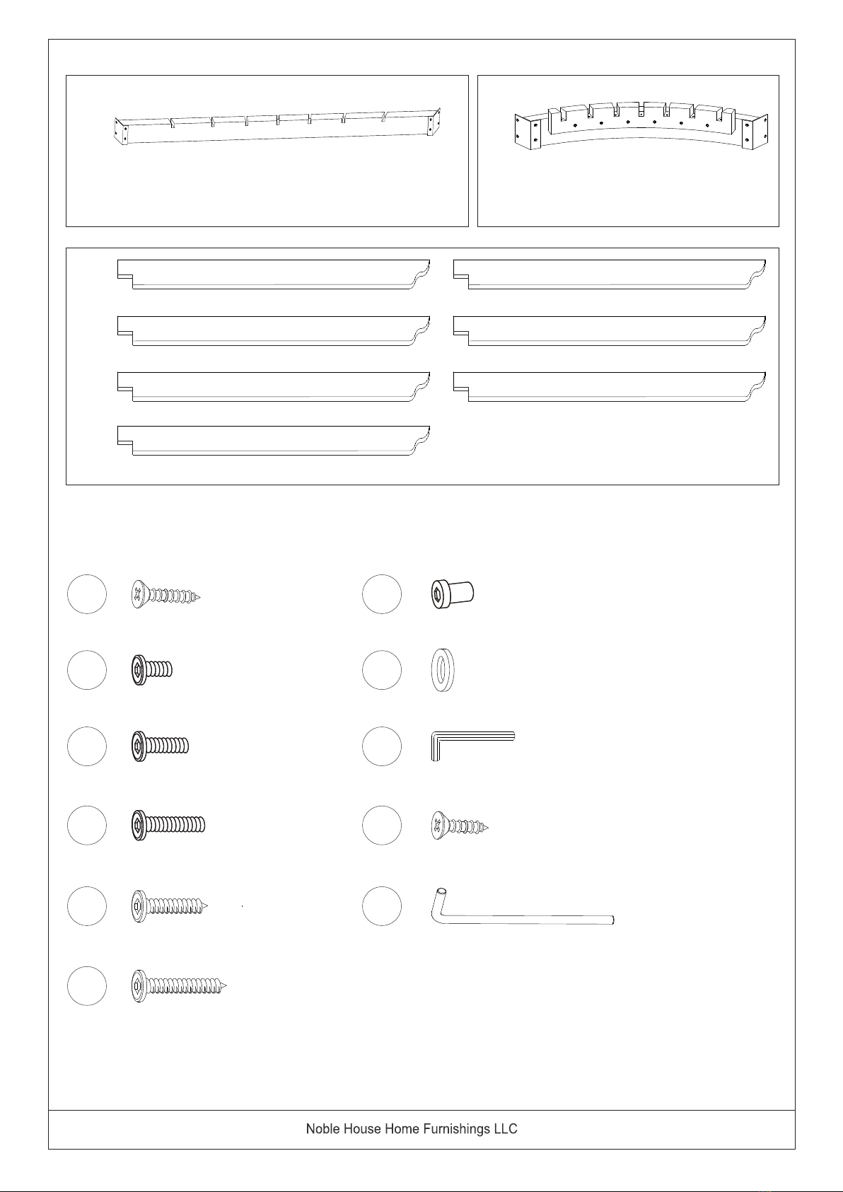
Bundle IV ) Parts of Front Roof Support Joist
D1 1
Front Roof Support Joist -
Left
D2 Front Roof Support Joist -
Right
D3 Front Joist Joint - Long
1
1
D4 Front Joist Joint - Key 1
D5 Metal Cleat 1
C 4
C 5
C 7
C 1
C 3
C 7
C 4
C 6
C 7
D5
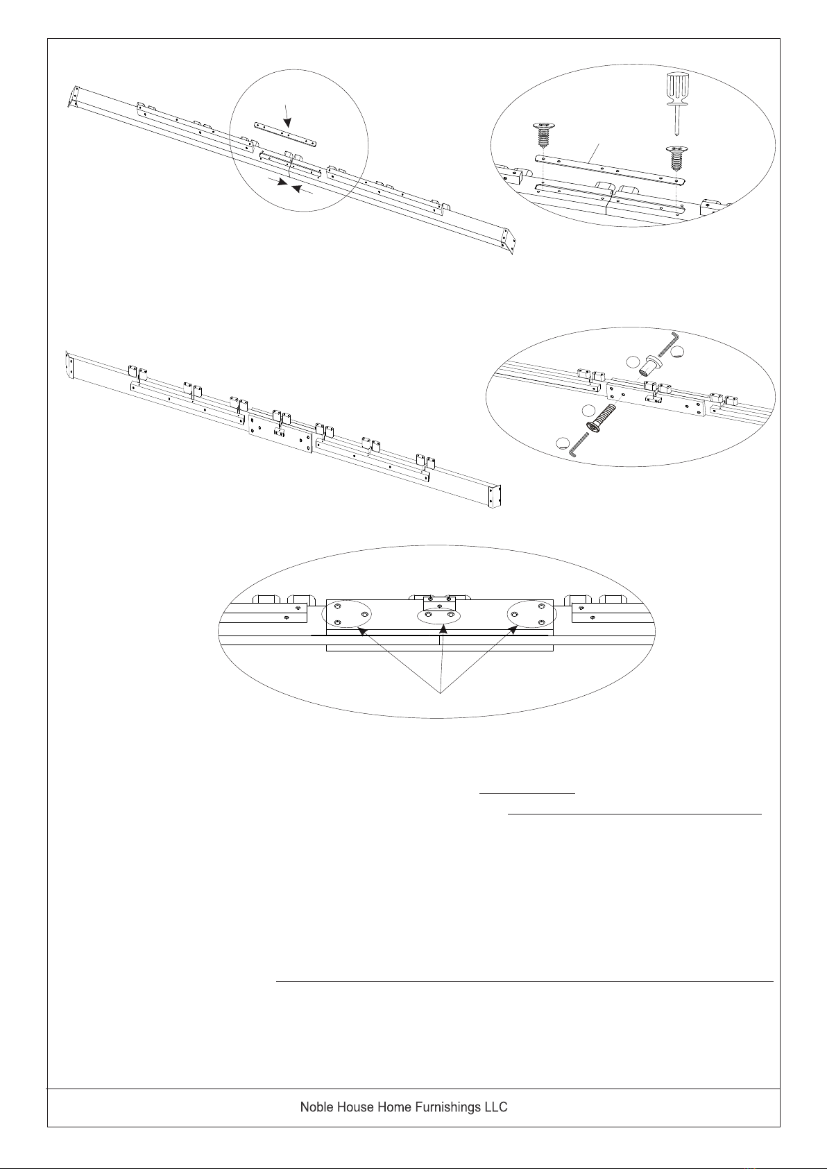
Note 5 : Upon completion of the assembly of the Front- Left & Right - Roof Support Joist 1
and 2 Joist, this completed Joist now becomes the FRONT ROOF SUPPORT JOIST.
Please ensure all Bolts and Screws are FULLY tighten after these are assembled.
The Metal Cleat is placed and sandwiched between the Wood Joists.
Do make sure the screw holes are well aligned to the holes in the JOIST KEY,
Front Roof Suppost Joist - LEFT and RIGHT and the FRONT Joist.
There are a total of 8 Bolts and 8 Sleeve Nuts to be affixed at this connected joint.
8 OF 46
D1
D2
D5
Connect Joists Hole
4
9
9
7
9 OF 46
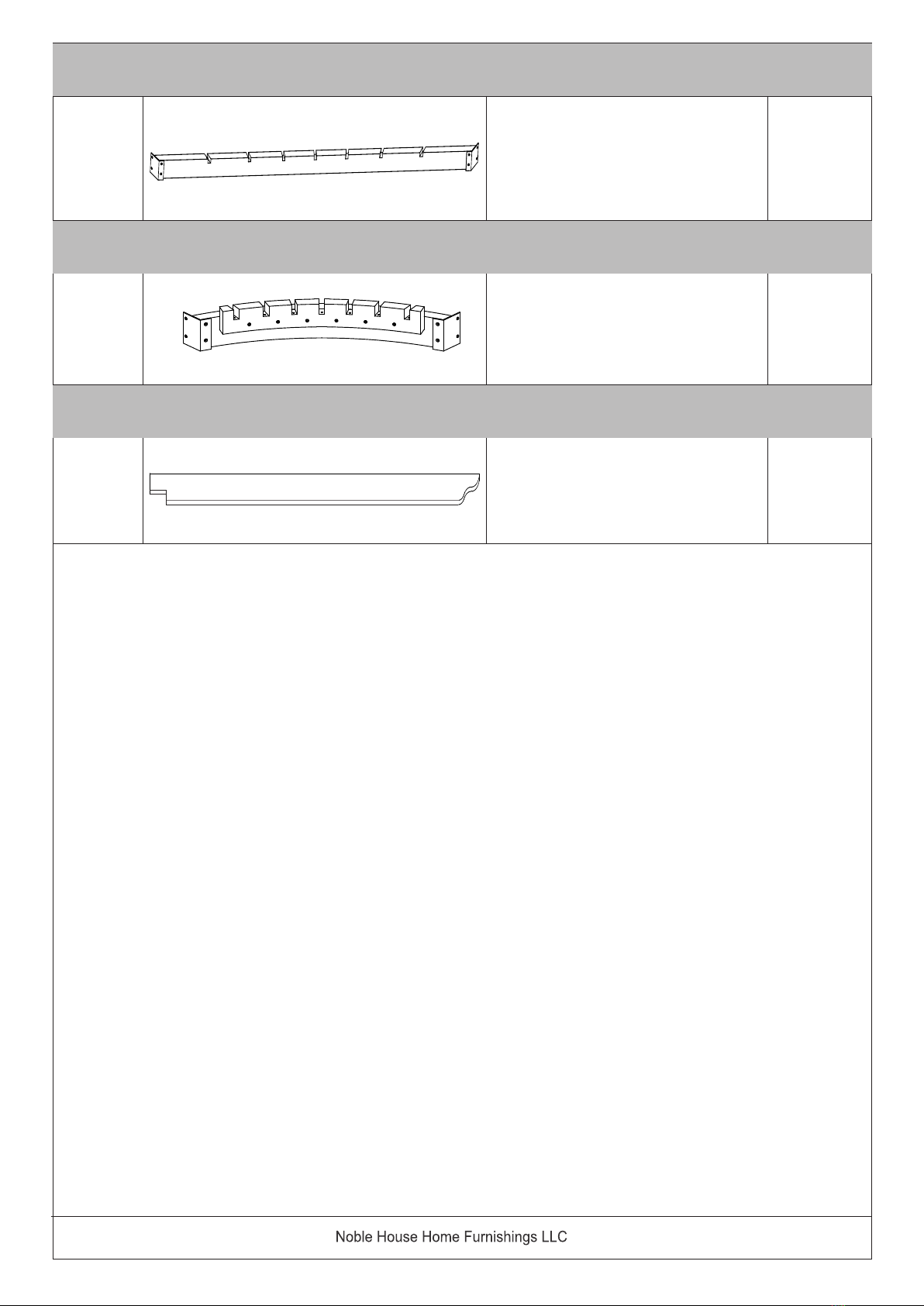
Note 6 : The above Components forms the Roof Support Joists and Roof Slats :
Component E - is the Middle - Roof Support Joist
Component F - is the Corner - Roof Support Joist
Component G - is the Roof Slats
E1
Middle Roof Support Joist
FCorner Roof Support Joist
GRoof Slat
1
7
Component V. ) Middle Roof Support Joist
Component VI. ) Corner Roof Support Joist
Component VII. ) Roof Slats
10 OF 46
10
11
12
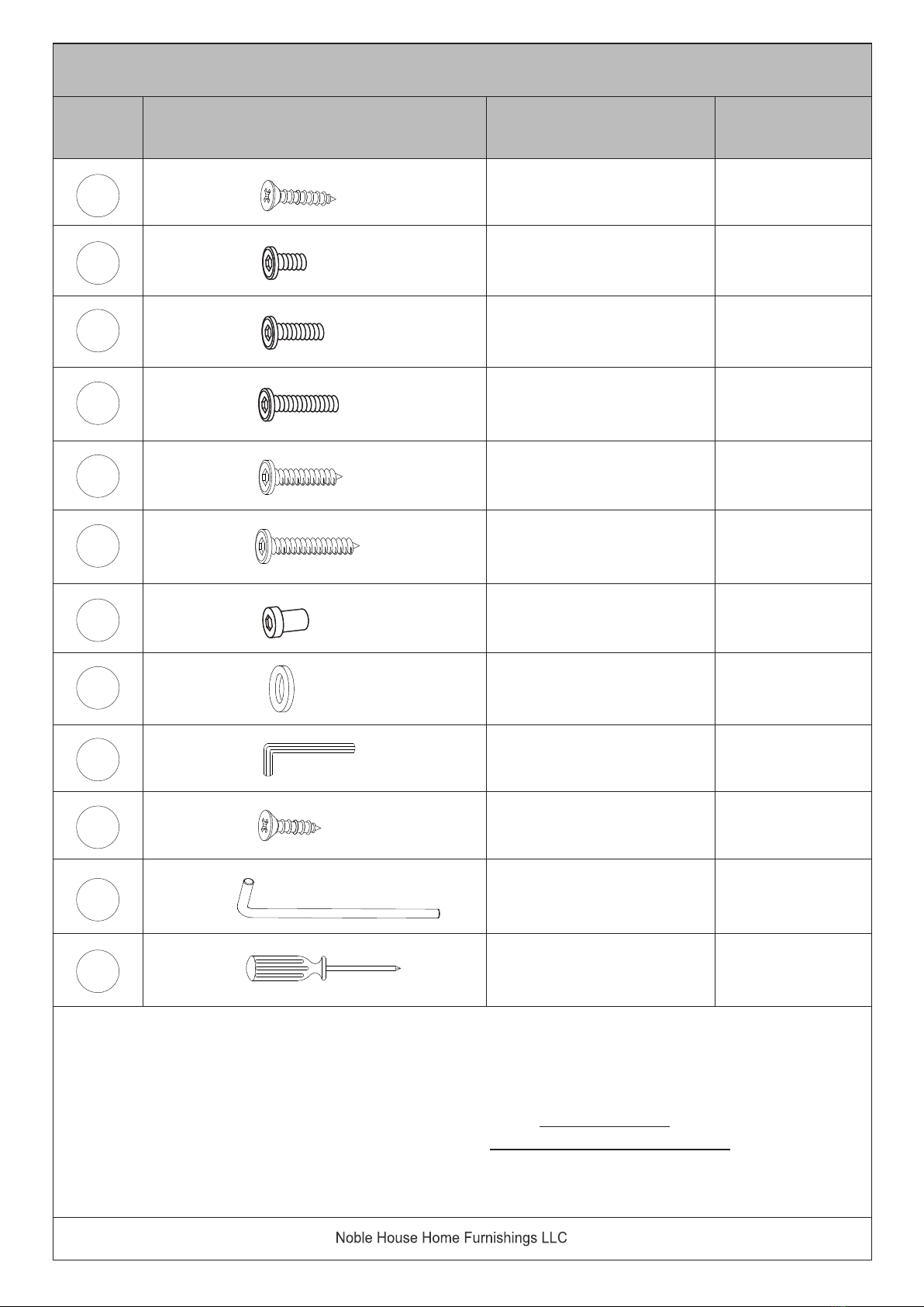
Note 7: Quantity in the Hardware List included extra hardware for each type of hardware.
During assembly you only need to reference the part number as noted in each step. This will
make finding the correct hardware easier.
Note 8 : This PERGOLA must be affixed / used on a FLAT / NONE SLOPED GARDEN GROUNDS.
The above illustrated Garden Stake Hardware - NOT provided.
The above illustrated Garden Stake is for Grass Ground Surface only.
Note 9 : Pillar Mounting Hardware to Concrete Flooring is NOT included/ NOT provided in this kit.
Note 10 : Please confirm with your local Building Permit Office to determine the correct hardware for
the other surfaces you intend to fix / hoist up the Pergola.
1
Hardware List
Picture Description QTY
No.
17
Screw
(M4x40mm)
215
Bolt
(M6x15mm)
329
Bolt
(M6x45mm)
411
Bolt
(M6x60mm)
559
Screw
(M7x50mm)
626
Screw
(M7x70mm)
751
Sleeve Nuts
(M6x18mm)
815
Flat Washer
(Ø6.5/16x1mm)
94
Allen Wrench
(M4 x 80mm)
3
Screw
(M4x15mm)
12 (Not
provided)
Garden Stake
(M10 x 300 mm)
Not
provided
Screw Driver
11 OF 46
Parts of Inner and Outer Joists, connected to become the RIGHT and
LEFT : Inner and Outer Joists.
Assembly Preparation
Parts of PILLARs.
A1 A2
A3 A4
A5
Parts of Foot Base
& Foot Aprons
B1
B2
B3
C1
C2
C3
C4
C5
C6
C7
C1
C4
D1 D2
D3 D4
D5
Parts of FRONT - Roof Support Joist
EF
Component - MIDDLE - Roof
Support Joist
Component - CORNER - Roof
Support Joist
G
Component - Roof Slats
11
10
9
8
7
6
5
4
3
2
1 x 17
x 15
x 29
x 11
x 59
x 26
x 51
x 15
x 4
x 3
x 12 (Not
provided)
HARDWARE PACK
12 OF 46
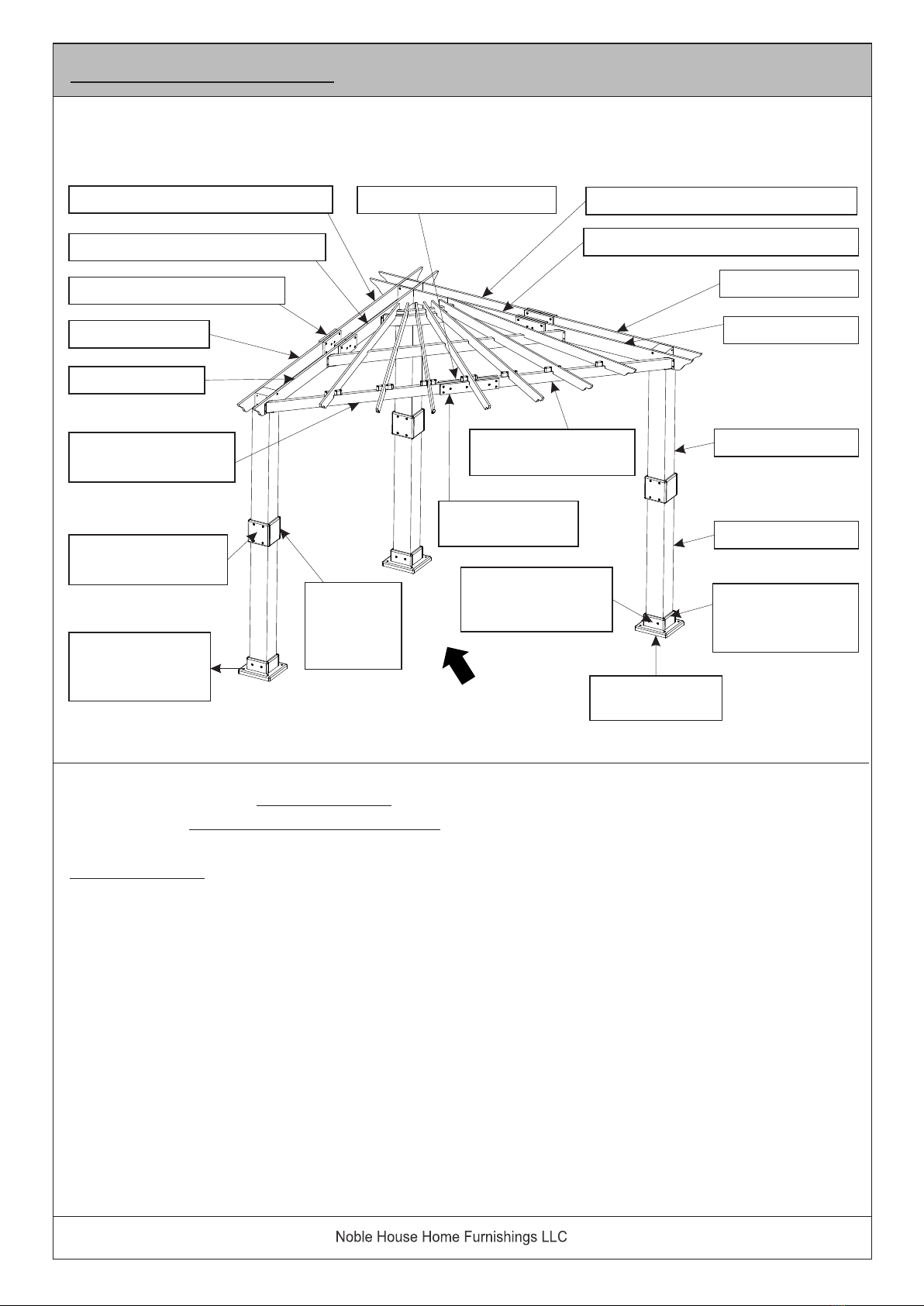
The above image - OVERVIEW 1 - gives you an overview on all the parts that
needs to be joined and or connected to become Components that will facilitate
towards the assembly, to become a complete Pergola as shown right below in
OVERVIEW 2.
13 OF 46
Assembly Steps
OVERVIEW 1.
Inner Slotted - Joist - Left (C6)
Outer Slotted - Joist - Left (C3)
Joinery - Short Joist (C7)
Outer Joist (C1)
Inner Joist (C4)
Inner Joist (C4)
Outer Joist (C1)
Inner Slotted - Joist - Right (C5)
Outer Slotted - Joist - Right (C2)
Front Joist Joint - Key (D4)
Front Roof Support
Joist - Left (D1)
Pillar Mid : Joinery
Slide Panel (A5)
Mounting Points
for Garden
Stakes Pillar Base :
Foot Base (B1)
Pillar Base : Foot
Apron - Anchor
Panel (B2)
Pillar Mid
Joinery
- Anchor
Panel (A4)
Lower Pillar (A2)
Upper Pillar (A1)
Pillar Base : Foot
Apron - Slide
Panel (B3)
Front Joist Joint
- Long (D3)
Front Roof Support
Joist - Right (D2)
Front

2 Ladders are required for assembly.
Save all packaging until completion of assembly.
Assemble on a clean non-marring surface
Do not assemble on flooring or carpet.
Have 4-5 adults in the assembly.
Read instructions, cover to cover.
In image OVERVIEW 2 above, it is intended to give you an overview on all the
COMPONENTS that are to be assembled to become the Pergola.
14 OF 46
OVERVIEW 2.
RIGHT - Inner Joist
Front
Pillar
MIDDLE - Roof Support Joist (E)
RIGHT - Outer Joist
CORNER - Roof Support Joist (F)
LEFT - Outer Joist
LEFT - Inner Joist
ROOF Slats ( G)FRONT -Roof
Support Joist
15 OF 46
Step 1
As the Pergola is tall, wide and heavy, we recommend :
1. ) That you identify and mark your ideal location where to place / position
this Pergola. By so doing, would mean minimal moving about of the partial
and or fully assembled Components and Pergola. Moving about the partially
assembled Components and or the assembled Pergola can bring about injury
and or damage(s) to the Pergola.
2. ) Unpack and place all parts on a Clean and Non-Marring Surface.
3. ) Place all parts in "group / bundle" as recommended above in the above
introduction.
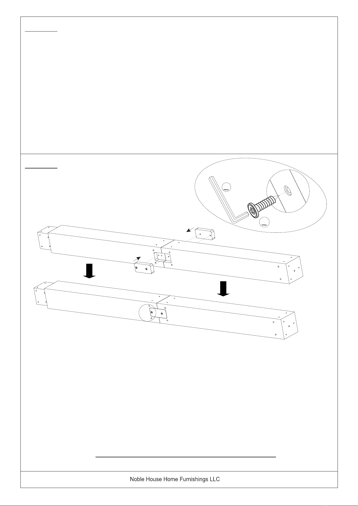
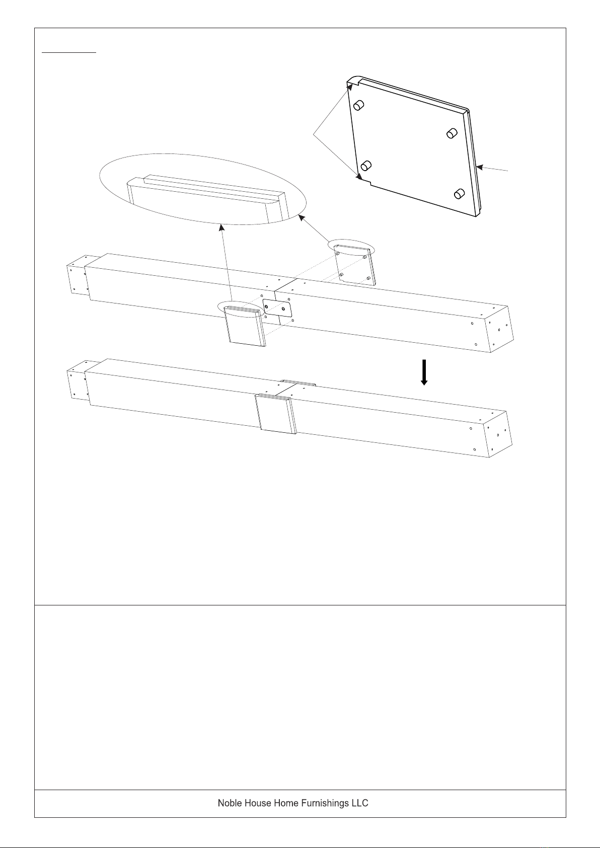
Step 2
Place, Upper Pillar (A1) to Lower Pillar (A2) as shown above.
Affix Upper Pillar (A1) to Lower Pillar (A2) with the Post Joint - Key (A3) and
Screws (⑥). Use the Allen Wrench (⑨), to affix the screws.
There are a total of 4 ( four ) Screws to be affixed.
Repeat the same steps for the second piece of Post Joint Key ( A3).
Repeat the same steps above for the remaining 2 ( two ) pillars.
Upon completion, FULLY SECURE AND TIGHTEN ALL SCREWS, in this partially
assembled Pillar.
A3
A1
A2
A3
6
9
GROUND END
UPPER END
16 OF 46
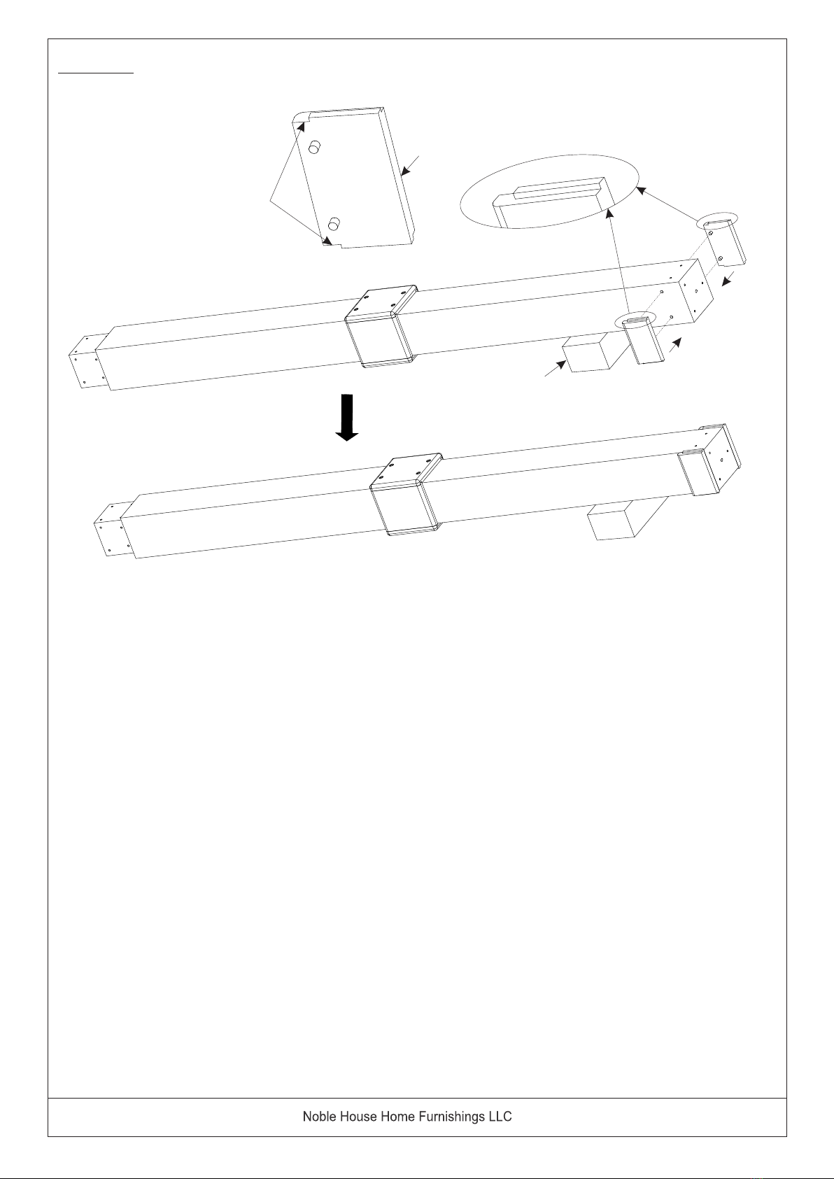
Step 3
There are 2 (two) pcs of Pillar MID JOINERY - Anchor Panel ( A4 ) slats.
There is a distinct Instep at the Upper portion of this Anchor Panel.
These Mid Joinery panels has Pre-attached Wooden Dowels.
Ensure there are 4 ( four ) pieces of pre-attached Wooden Dowels on each
Anchor Panel before assembly.
Affix this Pillar Mid Joinery - Anchor Panel slat to the Pillar as shown above.
A4
A4
Upper
Lower
A4
GROUND END
UPPER END
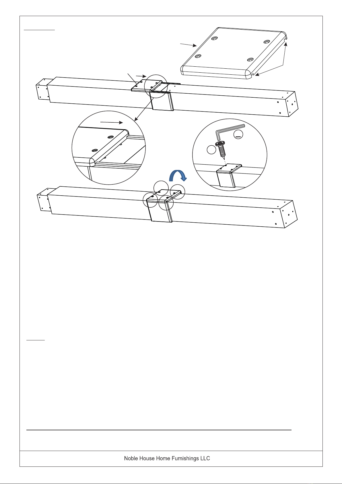
Step 4
Final assembly to the Pillars :
Slide Panel ( A5 ) has a distinct open groove at the sides of the panel, as shown in the picture.
At this step, One Partner shall hold firmly to the previously attached 2 ( two ) pieces of MID JOINERY - Anchor Panel ( A4 )
from Step 3.
The other Partner shall place and position Slide Panel ( A5 ) between the 2 ( two ) pieces of Pillar Mid-Joinery.
Push slide this Slide Panel ( A5 ) to place.
Next, using Allen Wrench (⑨), proceed to secure SLIDE PANEL ( A5 ), with Screws (⑤), to the Pillar.
Do not fully tighten each screw before going on to the next, as this may cause warpage.
Affix these Screws in a sequential manner.
Secure each Screw up to 70% - 80% and move on to the next Screw.
Upon completion assembly of these 4 ( four ) Screws, go back to the First Screw and in a sequential manner,
FULLY TIGHTEN all 4 ( four ) Screws, to secure this Slide Panel ( A5 ),
Repeat the above same steps in the assembly of the other Slide Panel ( A5 ).
Repeat the above same Steps 2 and 3 of assembly, for the remaining 2 ( two ) Pillars.
FULLY SECURE AND TIGHTEN ALL Screws in ALL 3 ( three ) Pillars, before moving on to Step 5.
5
9
A5
Upper
Lower
A5
17 OF 46
18 OF 46
Step 5
In Step 5, this assembly step is to affix the FOOT APRON - Anchor Panel (B2) to the Pillar.
Each FOOT APRON panel has 2 (two ) Pre-attached Wooden Dowels.
Each FOOT APRON panel has a distinct Upper and Lower feature.
For ease of assembly, place a box or an object to prop up the Pillar, at the foot base end, as shown above.
Then proceed to attach the FOOT APRON - Anchor Panel (B2), to the Foot Base of the Pillar, as shown above.
Upper
Lower
B2
B2
Box
B2
GROUND END
UPPER END

19 OF 46
Step 6
Here, in Step 6, it would require 2 people to assemble the Foot Apron.
At this step, One Partner shall hold firmly to the previously attached 2 ( two ) pieces of
FOOT APRON - Anchor Panel (B2) from Step 5, above.
The other partner shall place and position the FOOT APRON - Slide Panel (B3) between
the 2 ( two ) pieces of FOOT APRON - ANCHOR PANEL ( B2 ).
Push slide Foot Apron - Slide Panel ( B3 ) into place,
Use the Allen Wrench (⑨), tighten the Screws (⑤).
There are 2 ( two ) Screws per Slide Panel, tighten these in a sequential manner.
Then turn the Pillar 180 degrees and repeat Steps 6 here, to affix the other
Foot Apron - Slide Panel ( B3 ).
Upon completion - check and FULLY SECURE and TIGHTEN all 4 ( four ) Screws.
The next step would be to do the same steps with the remaining 2 ( two ) Pillars.
Attach all Foot Aprons - Anchor Panels and Foot Aprons - Slide Panels into position.
FULLY SECURE AND TIGHTEN ALL SCREWS for all 3 ( three ) Pillars.
B3
Box
5
9
Upper
Lower
B3

B1
Box
B1
9
6
B1
B1
Upper
Lower
Step 7
Here, in Step 7, is a single-man job, in the assembly of the Foot Base to the Pillar.
Keeping the Pillar in the same propped position from above, proceed to attach the Foot Base ( B1 ).
Attach the FOOT BASE ( B1 ) to the Pillar with Screws (⑥).
Using the Allen Wrench (⑨), secure and tighten all 3 ( three ) Screws (⑥) into the base of the Pillar,
as shown above.
There are a total of 3 Screws to be affixed per Foot Base (B1).
Repeat this Step 7 for the remaining 2 ( two ) Pillars.
The completion of assembly Steps 5, 6 and 7 here, is that you now have 3 ( three ) Pillars, fully assembled
with Foot Aprons with Foot Base.
Ensure all the Screws of these Foot Bases are FULLY SECURED AND TIGHTENED.
To assist the flow of assembly into a Pergola, you may place each Pillar to the previously marked locations.
Step 8
SAFETY REMINDER :
Upon completion at Step 7 above, you would have assembled all 3 (three ) Pillars, complete with
Foot Bases.
Before moving on to the next part of the Pergola assembly, go back and check and
ENSURE ALL BOLTS AND SCREWS at ALL ASSEMBLY POINTS for ALL 3 (three) Pillars,
are FULLY SECURED AND FULLY TIGHTENED into position AT ALL POINTS.
Here below in Step 9 & 10, involves the assembly of the INNER and OUTER Joist to the Pillars.
The function of the Inner and Outer Joists will be attached to the top of the pillars to become
the core support for the Roof Slats.
20 OF 46
Table of contents
Other Noble House Home Furnishings Lawn And Garden Equipment manuals

Popular Lawn And Garden Equipment manuals by other brands

Sunforce
Sunforce SOLAR user manual

GARDEN OF EDEN
GARDEN OF EDEN 55627 user manual

Goizper Group
Goizper Group MATABI POLMINOR instruction manual

Rain Bird
Rain Bird 11000 Series Operation & maintenance manual

Cub Cadet
Cub Cadet BB 230 brochure

EXTOL PREMIUM
EXTOL PREMIUM 8891590 Translation of the original user manual


Vertex
Vertex 1/3 HP Maintenance instructions

GHE
GHE AeroFlo 80 manual

Land Pride
Land Pride Post Hole Diggers HD25 Operator's manual

Yazoo/Kees
Yazoo/Kees Z9 Commercial Collection System Z9A Operator's & parts manual

Premier designs
Premier designs WindGarden 26829 Assembly instructions

Snapper
Snapper 1691351 installation instructions