nocturn UANVB Katana User manual

Table of Contents
Product Overview……………………………………..1
Back Diagram………………………………………….2
I.P.D. Screw
Tensioner Screw
LEMO Port
I.P.D. Friction Lock Stop
Tensioner Plate………………………………………..3
I.P.D. Stop Adjustment Diagram……………………5
I.P.D. Reset
I.P.D Stop Setting……………………………………..6
Individual On/Off Articulation Diagram…………..7
Articulation Power On
Articulation Power Off………………………………8
Front Diagram………………………………………...9
Purge Screw
Infinity Stop Ring
Focus Distance Adjustment
Diopter Adjustment
Battery Cap
Diopter Housing
Eyepiece Locking Ring
O-Ring
Objective Lens……………………………………..10
Trouble Shooting ………………………………….13

Product Overview
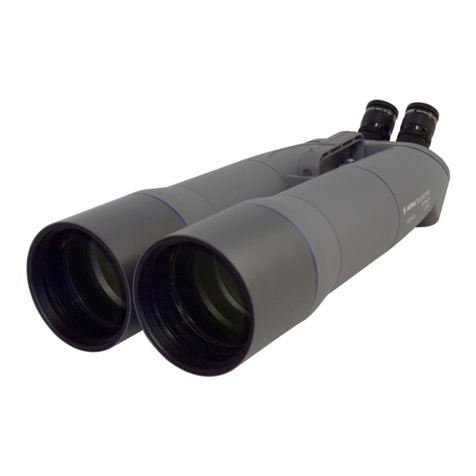
The UANVB Katana
(Ultralight Articulating Night Vision Binocular)
The Katana is a fully articulating night vision binocular that has a built in on/
off power function when pods are rotated into the out
(up) and in (down) positions. The pod on/off feature will operate individually
per pod. Left up/down will operate power on/off for left image intensifier
tube pod left. Right pod up/down will operate power on/off for right image
intensifier tube pod right. The binocular device features an all new “Friction
Lock Interpupillary Adjustment” system, the I.P.D stops that will allow the
user to set IP stop distance relative to user preference (space from left eye
to right eye). The binocular device uses infinity locking rings that will allow
user (or manufacturer) to set maximum focus distance on the front
objective lens to infinity enabling quick adjustment between “close” and
“far” focus distance with a firm stop at maximum focus every time. The
night vision binocular will feature a rear tensioning plate fastening the pod
housings to the bridge (center) of the device. The tensioning plate will
feature 1 screw on each plate, that when tightened or loosened will adjust
friction tension, that translates to how stiff or soft the ability to articulate out
(up) and in (down) will feel. Loosened being a softer looser articulation and
tighter being a stiffer tighter articulation. The night vision device will have a
hard on/off power button that will power the device on and will only power
off if clicked into the power off cycle or if pods are articulated into the out
(up) position at an angle appropriate to activate individual power off
feature. If power is hard cycled on and pods are articulated (rotated) into
the in (down) position the individual pods will power the image intensifier
tubes on respective to the side that is being articulated into the on (down)
position. The night vision binocular will feature a dovetail for mounting to
dovetail compatible helmet mounts. The night vision binocular will feature a
single purge port on each pod used for purging of each pod and will be
sealed with a purge screw and o-ring.
1

Back Diagram
2

1.I.P.D. Screw – The Interpupillary Distance screw has a factory
torque setting of 8.5-inch pounds. The I.P.D. screw should not be
adjusted by the user. The I.P.D. screw torque setting ensures that
the interpupillary distance stop has enough resistance to provide
a sure stop upon articulation down but may still be pushed past
the stop limit for user inner pupillary distance adjustment.
Adjustment or tightening of the I.P.D. screw may result in loss of
I.P.D. stop function, loss of I.P.D. stop function quality, or potential
shearing (breaking) of titanium screw head.
2. Tensioner Screw – The tensioner screw has a factory torque
setting of 6.5-inch pounds. The tensioner screw may be adjusted
by the user for articulation stiffness preference. The tensioner
screw uses a T10 torx driver bit for adjustment. Tightening the
tensioner screw will give the user a stiffer and tighter feel upon
articulation. User should not tighten tensioner screw excessively.
Do not exceed 10-Inch pounds. Excessive tightening will inhibit
the pods ability to articulate and could result in damage of screw.
User should only tighten tensioner screw slightly if stiffer
articulation is desired.
3. LEMO Port- The baseplate of the night vision binocular bridge
will have a LEMO port compatible with the push pull connector
(3b.). The LEMO port will allow the user to connect the night
vision binocular to an external battery pack to provide longer
operating duration through the use of multiple batteries in the
power pack. The user should be familiar with the use of LEMO
connectors and should know to orient the connector with the
indication dot on the male end connector and female end port
before inserting the connector into the port on the night vision
device. Twisting of the connection to find orientation may result in
damage of the port or connection pins and render the LEMO port
inoperable.
3

4. I.P.D. Friction Lock Stop – The interpupillary friction lock stop
will enable the user to set the stopping point of each pod when
rotated or articulated into the down position.
5. Tensioner plate – The tensioner plate is the mechanism used
to fasten the pod to the bridge of the device. The tensioner plate
will control the stiffness of motion when rotating pods for
articulation control.
4

Interpupillary Distance Stop Adjustment
5

6. I.P.D. Reset Position – The I.P.D. friction lock mechanism may
be pushed past the point of stop provided by the protruding tooth
of the tensioning plate. The user can push against this protruding
tooth to reset the I.P.D. mechanism.
7. I.P.D. Stop Preference – The I.P.D. stop can be set by the user
by articulating (rotating) the pod in (down) to the users desired
interpupillary position. The user can push the I.P.D. mechanism
past the stopping point by articulating the pod until desired position
is reached. Once set to the preferable I.P.D nothing more has to
be done.
6

Individual On/Off Articulation
7

8. Articulation Power On – When the device is powered on
using the battery cap on cycle or external power pack set to ON
the individual pod will be powered on while in the in (down)
position.
9. Articulation Power Off – When the device is powered on
using the battery cap on click cycle or external power pack set to
ON the individual pod will be powered OFF while articulated
(rotated) to a position that exceeds the position at which the pod
would power on.
8

Front Diagram
9

10. Purge Screw – The purge screw will be fitted with a small O-
ring whose purpose is to seal the port used to purge the night
vision binocular. The purge screw should not be removed by the
user. If the purge screw is removed or loosened for any reason the
seal of the pod may be breached allowing moisture to enter the
pod. Moisture will expose the internal components to potential
corrosion, and may cause the optics to fog over internally.
11. Infinity Stop Ring – The infinity stop ring can be set by the
manufacturer on a test bench or by the user manually. When the
objective lens (front) is set at infinity focus the stars in the sky are
perfectly in focus. The infinity stop ring will be threaded outward
towards the objective lens until contact is made and the objective
lens is touching the infinity stop ring. The grub screw, a small
screw threaded into one of the holes on the infinity stop ring can
then be threaded inward and tightened against the threads of the
pod to ensure that the infinity stop ring will be locked in place.
Excessive torque should not be used to tighten the grub screw and
the user should take proper care to ensure they only tighten the
screw enough to stop the infinity stop ring from threading or
unthreading with an appropriate amount of force. Once infinity stop
ring is set the user can transition between focus distance at leisure
but can return to infinity focus distance quickly and easily.
12. Focus Distance Adjustment - The objective lens (front) is the
lens that will control the focus distance of the night vision binocular
optics. The user will twist the objective lens so that the lens
threads in and out of the end of the night vision binocular pod.
While looking through the night vision binocular that is powered on
with a functioning image intensifier tube and appropriate lens set,
the objective lens can be twisted in and out by hand and the user
will observe sharp focus point moving from
10

close distance to maximum distance gradually while twisting the
lens. The lens can be unthreaded to a stopping limit that will be
retained by the night vision binocular pod preventing the lens from
unthreading completely and falling off. This will ensure that the
seal of the night vision binocular cannot be breached, and purge
seal will be maintained.
13. Diopter Adjustment – The outermost ring of the diopter
assembly (rear) will be the diopter adjustment ring. As the diopter
adjustment ring is twisted the diopter cell (lens) will move in and
out within the diopter assembly from -6 to +2 diopter. As the user
looks through the night vision binocular that is powered on with a
functioning image intensifier tube installed and appropriate optic
pair properly installed, the diopter adjustment ring can be twisted
and the image will gradually adjust until a comfortable setting is
achieved for/by the user. Adjust until your eyes are comfortable
and a 1:1 image size can be seen through the eyepiece as
compared to an un-aided eye.
14. Battery Cap – The battery cap is the night vision binocular
ON/OFF switch. When clicked the battery cap while cycle between
power on and off with each click. To ensure proper contact the
battery cap must be threaded on and tightened properly. The
battery cap may need to be tightened firmly to achieve proper
connection.
15. Diopter Housing – The diopter housing assembly should be
installed by the manufacturer or builder. The diopter housing
assembly should not be threaded or unthreaded by the user. The
user should take proper precautions to ensure they are not
unthreading the diopter housing assembly. If the diopter housing
assembly is adjusted (twisted) in any direction for any reason the
optical collimation of the image while using the night vision
binocular may be inhibited. If collimation is out of orientation the
user may experience an uncomfortable experience that can cause
headaches, disorientation, eye strain etc.,
11

16. Eyepiece Locking Ring – The eyepiece locking ring will be
used to lock the diopter housing assembly in place. The user
should not adjust the eyepiece locking ring. If the eyepiece
locking ring is unthreaded or moved for any reason the diopter
housing assembly may move and the visual collimation of the
night vision binocular may be inhibited. The eyepiece locking ring
will be set by the builder after proper collimation is achieved.
There are no set screws holding the eyepiece locking ring in
place, the user should take proper care to ensure they do not
unthread or thread the eyepiece locking ring.
17. O-Ring – The battery cap O-Ring will provide the night vision
binocular battery port with a proper watertight seal. The battery
cap O-Ring should be regularly lubricated by the user using
silicone-based lubricant to reduce wear of the O-Ring. If the O-
Ring becomes worn or damaged please contact Nocturn
Industries for a replacement.
18. Objective Lens – The objective lens is the front lens of the
night vision binocular device. The objective lens is responsible for
the optical focus of the night vision binocular.
12

Trouble Shooting
No Power
Battery - If the night vision binocular is not powering on start by
ensuring there is a fresh CR123A battery in the device in the
proper positive negative orientation. Ensure that the night vision
binocular pods are in the in (down) position within the range
where the independent on feature will be activated.
Battery Cap – If the night vision device will not power on ensure
that the battery cap in tightened appropriately to make proper
contact. Ensure that the night vision binocular pods are in the in
(down) position within the range where the independent on feature
will be activated.
O-Ring – If the night vision binocular will not power on try
removing the O-Ring of the battery cap and re-install the battery
cap without the O-Ring, tighten the battery cap to appropriate
tightness and try to power the unit on. Ensure that the night vision
binocular pods are in the in (down) position within the range where
the independent on feature will be activated.
Can’t Focus
Infinity Stop Ring – Make sure that the infinity stop ring has not
unthreaded or moved in any way. If it is suspected that the infinity
stop ring has been moved start by unscrewing the small set screw
or screws that fastens the infinity stop ring in place. Thread the
infinity lock ring all the way in against the pod of the night vision
binocular and then look through the night vision binocular as you
adjust your focus distance. Refer to front diagram for information
on how to reset infinity stop ring in place.
13

I.P.D. Stops are loose
I.P.D. Screw – Rotate (articulate) the pod in and out (up/down) to
evaluate whether the I.P.D. friction lock system has an appropriate
amount of stopping force when I.P.D. stopping mechanism
reaches the stopping point of the tooth on the tensioner plate. If it
is found that the I.P.D. friction lock stopping force is too weak it is
recommended that your unit be returned for service. If the user
wishes to perform the service the screw must be removed, thread
chased for cleanliness (this is crucial) Blue 243 Loctite and Loctite
SF7471 primer must be applied properly and the screw, washer,
and I.P.D. mechanism must be re assembled and screwed to a
torque of 8.5-inch pounds. Pods must not be rotated in any way
until Loctite has fully cured.
14
This manual suits for next models
1
Table of contents


