Nohken FM-16 User manual
-ADD 1 -
Read and understand this manual for safely usage.
・This manual describes the product of standard specification. Read the other manual for
the product of explosion-proof specification.
・This manual describes the handling, inspection and adjustment of the product which
model is mentioned on cover page. Read and understand this manual before handling.
・Follow the additional document and/or direction, submitted by NOHKEN INC. and our
distributor or agent, even if the terms are mentioned in this manual.
・Save this manual in proper place being available to refer immediately.
・The specification of product mentioned in this manual may not be satisfied by the
condition of environment and usage. Check and consider carefully before using.
・Contact to sales office at NOHKEN INC. for any question or comment about this manual
and product.
The followings are the description of the terms in this manual.
WARNING
Indicates a potentially hazardous situation which, if not pay
attention, could result in death, serious injury or serious
disaster.
CAUTION Indicates a hazardous situation which, if not pay attention,
may result in minor or moderate injury or damage to device.
Indicates prohibited matter. The explanation with this mark
shall be followed
Indicates instructed matter. The explanation with this mark
shall be followed.
-ADD 2 -
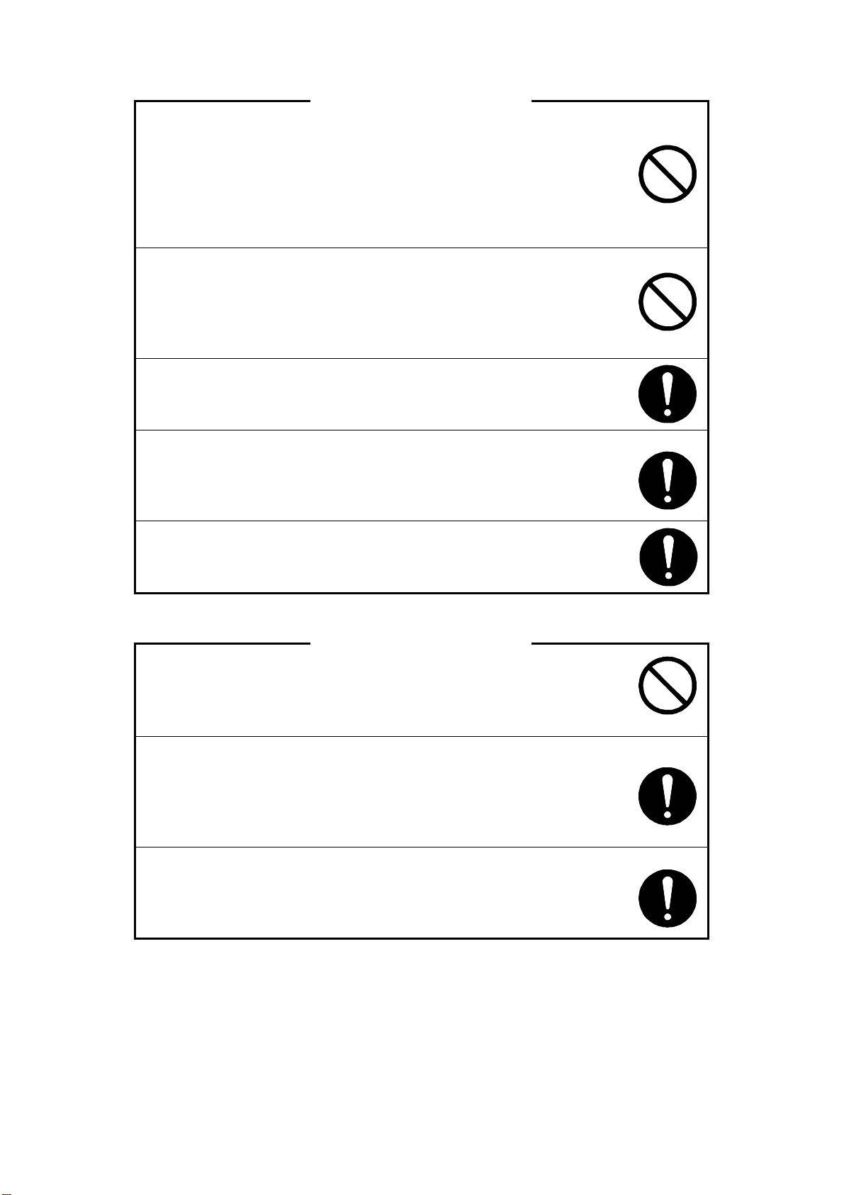
WARNING
This product is not explosion-proof construction. Do not install
this product to the place where the flammable gas or vapor is
occurred.
If installed, the flammable gas or vapor may be ignited, and
serious disaster may be occurred. Use the product of
explosion-proof construction in this case.
Do not modify or disassemble the product. Otherwise, the
product and connected device may be malfunctioned, damaged,
fired, or miner injury and electric shock may be occurred.
(Follow the additional document and/or direction, submitted by
NOHKEN INC. and our distributor or agent.)
Turn off the power, before wiring and inspection. Otherwise,
electric leakage, fire caused by short circuit, and electric shock
may be occurred.
Ensure the wire is properly connected. The product and
connected device may be malfunctioned, damaged, fired, or
miner injury and electric shock may be occurred by improper
wiring.
Turn off the power immediately, if the smoke, strange smell and
sound are occurred.
Do not use it until the problem is solved.
CAUTION
Avoid shock and rough handling to this product. The
product may be damaged by shock as dropping,
falling,throwing,knocking,lugging,andetc.
Follow the specification of operating temperature, operating
pressure, switch rating, and etc. Otherwise, the product and
connected device may be malfunctioned, damaged, fired, or
miner injury and electric shock may be occurred. Check the
manual or specification sheet.
Operation test shall be done before practical usage. If the
serious accident is expected to occur by malfunction of product,
the other operating principle of product shall be installed in
parallel.
-ADD 3 -
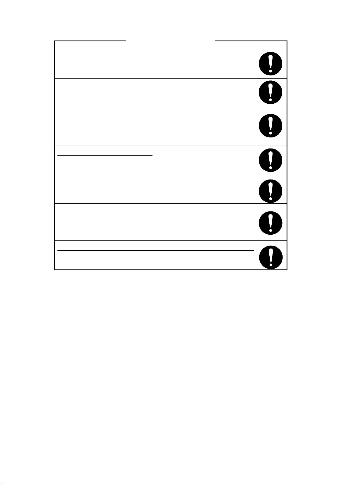
CAUTION
Check and deeply consider the chemical compatibility for
material of product in advance. The part especially float, which
is very thin, may be malfunctioned by miner corrosion.
Check and deeply consider the chemical compatibility
for material of product in advance.
Hold the stem very close to mounting point, when carrying,
installing, and removing. If hold the terminal box, it may be taken
off from the flange or plug, and the product may be damaged by
dropping.
The product is 50cm or longer
The product shall be kept in horizontally. The product and other
goods be damaged, and miner injury may be occurred by falling.
Earth terminal shall be grounded to JIS Class D ground (earth
resistance less than 100Ω). If not grounded, electric shock may
occurred by any accident.
Provide arrester or surge absorber to avoid electrical impact
such as lightning and static electricity. If not provide, the product
and connected device May be malfunctioned, damaged, and
fired, or miner injury and electric shock may be occurred.
In case of connecting inductive or lamp load to the product.
Provide protective circuit to the load to avoid over voltage and
over current. If not provide, the contact may be damaged.

-ADD 4 -
INTRODUCTION
A) This manual specifies the specification of general product. If you order special product,
some details of specification may be different with the manual.
B) We are glad to suggest and advice for Model selection and chemical resistant of
material, but final decision has to be made by the customer.
C) This manual has prepared with close attention. Ask sales office at NOHKEN INC. for
any question or comment about the contents of this manual.
D) For replacement parts
The quality of product has frequently improved, so same spare part may not be
supplied. In this case, replacement part or product may be supplied. Ask sales office at
NOHKEN INC. for details.
E) The contents of this manual are subject to change any time without notice due to the
improvement of product.
WARRANTY & DISCLAIMER
A) NOHKEN INC. warrants this product against defect in design, material and
workmanship for a period of 1(one) year from the date of original factory shipment.
B) The warranty only covers the damage of products. The secondary and third kind
disasters are not covered by NOHKEN INC.
C) NOHKEN INC. shall not be liable for the following.
C-a) Do not follow the description and direction in this manual.
C-b) Damage due to improper installation, wiring, usage, maintenance, inspection,
storing, and etc.
C-c) Repair and modification are done by the person who is not employee of NOHKEN
INC. and our distributor or agent.
C-d) Improper parts are used and replaced.
C-e) The damage is occurred by the device or machine except our products.
C-f) Improper usage. (See "Proper of usage" in chapter 1 in this manual)
C-g) Force Majeure including, but not limited to, fire, earthquake, tsunami, lightning, riots,
revolution, war, radioactive pollution, acts of God, acts of government or
governmental authorities, compliance with law, regulation, and order.
THE TERMS OF WARRANTY AND DISCLAIMER SHALL IN NO WAY LIMIT YOUR
REGAL LIGHT.

TABLE OF CONTENTS
MUST BE READ BEFORE USING
INTRODUCTION
WARRANTY & DISCLAIMER
NOTE TO USERS
TABLE OF CONTENTS
Page No.
1. PURPOSE OF USE
・・・・・・・・・・・・・・・・・・・・・・・・・
1
2. SPECIFICATIONS
・・・・・・・・・・・・・・・・・・・・・・・・・
1
2.1 Standard Specification
・・・・・・・・・・・・・・・・・・・・・・・・・
1
2.2 Outline Drawing
・・・・・・・・・・・・・・・・・・・・・・・・・
2
3. PRINCIPLE OF OPERATING
・・・・・・・・・・・・・・・・・・・・・・・・・
2
4. INSTALLATION
・・・・・・・・・・・・・・・・・・・・・・・・・
3
4.1 Unpacking
・・・・・・・・・・・・・・・・・・・・・・・・・
3
4.2 Installation Location
・・・・・・・・・・・・・・・・・・・・・・・・・
3
4.3 Installation
・・・・・・・・・・・・・・・・・・・・・・・・・
4
4.4 Installation Attitude
・・・・・・・・・・・・・・・・・・・・・・・・・
4
5. WIRING
・・・・・・・・・・・・・・・・・・・・・・・・・
5
6. ADJUSTMENT FOR INTERFACE DETECTION
・・・・・・・・・・・・・・・・・・・・・・・・・
6
7. TECHNICAL NOTES
・・・・・・・・・・・・・・・・・・・・・・・・・
6
8. MAINTENANCE/INSPECTION
・・・・・・・・・・・・・・・・・・・・・・・・・
7
9.TROUBLE SHOOTING
・・・・・・・・・・・・・・・・・・・・・・・・・
8

- 2 -
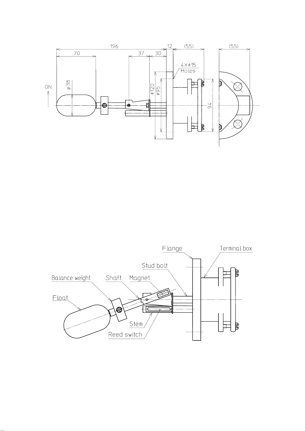
2.2 Outline Drawing
Fig. 1 Model FM-16
3. PRINCIPLE OF OPERATION
The Model FM-16 is designed to detect the interface between two liquids. By adjusting
the position of the balance weight (reference with Table 2) , the switch will detect
the interface of any liquids. This switch contain hermetically-sealed reed switch
within the stem or flange and a permanent magnet in the end of the shaft. As the float
rises or falls with the level of the liquid, the reed switch is activation by the magnet
in the end of the shaft. Fig. 2, 3 shows the high level operation (close ON rising
interface level).
Fig. 2

- 3 -
Fig. 3
4.
INSTALLATION
4.1 Unpacking
When unpacking, exercise caution and do not subject the unit to mechanical shock.
After unpacking, visually check the unit's exterior for damage.
4.2 Installation Location
The FM-16 should be installed in an area where the following conditions:
(1) The ambient temperature range is -10 ℃ to 60 +℃
CAUTION
Install a sun shield over the housing if exposed to direct sunlight.
Provide appropriate means to guard against moisture if temperature
is low. Otherwise, the unit may be damaged.
(2) The FM-16 should be located away from strong magnetic fields such as those
produced by motors or solenoid valves.
(3) Humidity and vibration are low.
(4) Ample space is provided for maintenance and inspection.

- 4 -
4.3 Installation
The FM-16 is installed horizontally from the exterior of tank at the level where
you wish to detect. Please use caution during installation. Maximum all wobble
impact is 100 m/s2. Shocks greater than 100 m/s2 may break the reed switch.
The FM-16 is provided with JIS 5K 40A or another specified flange. Nozzle length
and inside diameter must be sized correctly. A table of mounting flange details
(Fig. 4) is given below.
In case of installed, prepare a suitable mounting gasket and secure the FM-16 with
bolts.
Fig. 4
4.4 Installation Attitude
For FM-16, FM-26 depending on the installing position, the switch operations can
open or close. In case of used as a high level operation (close ON rising level),
the cable inlet should be positioned to the right. In case of used as a low level
operation (close ON falling level), the cable inlet should be positioned to the
left.
・
Fig. 5 shows close ON rising level.
・
The switch operations are easily changed by rotating the unit
180
°
.
Fig. 5
d = φ44 mm
A = L + 60 mm
(L is length of extension rod.
Standerd length : 30 mm
D = φ134 mm
- 5 -
5.
WIRING
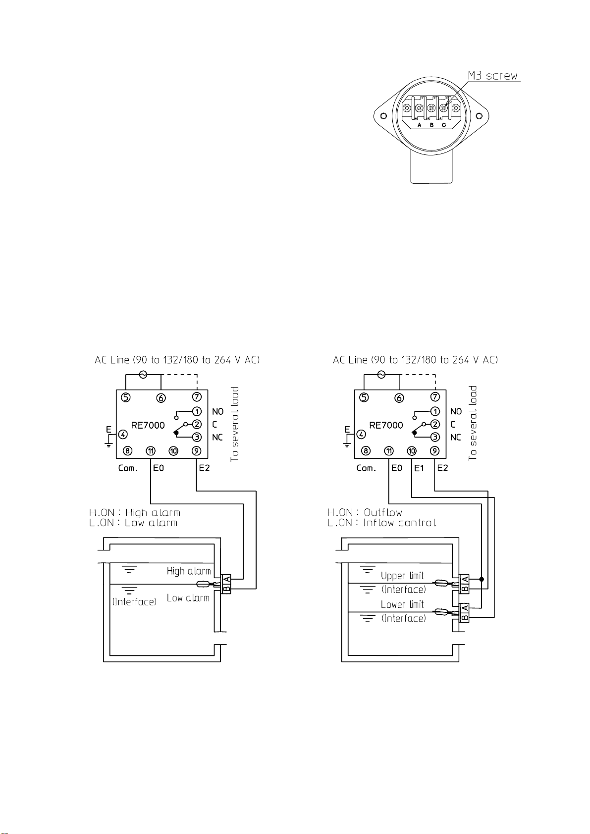
Fig. 6 denotes wiring of internal terminal box.
NOTE the following points ;
(1) Install compression terminals fitted to M3
screw to the inner conductor.
(2) The cable inlet must be properly fitted to
preserve the protection category IP44 and
to protect the sensor from rain, splashing
water, and so on. Fig. 6
(3) Reed switches are not designed for the direct starting of pumps, valves and
alarms. They are susceptible to damage from electric surges.
DO NOT EXCEED THE CONTACT RATINGS.
Contacts should be wired to relays or similar devices.
(4) We recommend the use of our relay unit Model RE7000.
The latching (holding relay) feature allows pumps, valves and other devices
to be turned on at one level and off at another. It also contribute to safety
since it allows lower voltage and smaller currents to be used with the FM-16.
For the relay unit Model RE7000, refer to Instruction Manual.
(1) Connection example A (2) Connection example B
NOTE ; Sensor operation are set ↑ON.
Fig. 7

- 6 -
6. ADJUSTMENT FOR INTERFACE DETECTION
The marking on the shaft designates the setting position where the intermediate
specific gravity is 0.96. First calculate intermediate specific gravity between
the two liquids. Then, move the balance weight in accordance with the Table 2.
For example, consider water (specific gravity : 1.0) and oil (specific gravity :
0.8). Intermediate specific gravity is 0.9. So, adjust position of the balancing
weight to match l= 31 mm.
Fig. 8
Table 2
I.S.G l mm I.S.G l mm I.S.G l mm
0.72 14 0.82 23.5 0.92 33
0.74 16 0.84 25.5 0.94 35
0.76 18 0.86 27 0.96 37
0.78 19.5 0.88 29 0.98 38.5
0.80 21.5 0.90 31 1.00 40.5
7. TECHNICAL NOTES
(1) Do not store this switch as following location.
・
High temperature and high humidity
・
Corrosive field
・
Dust field
・
Magnetic field
(2) Do not give this sensor mechanical shocks. [Fig. 9(a)]
(3) Do not install this sensor near inflow or outflow. [Fig. 9(b)]
(4) Keep the sensor away from magnetic material such as iron dust. [Fig.9(c)]
(5) If the liquid has sediment or suspended solid, clean the wetted parts.
[Fig. 9(d)]

- 7 -
Fig. 9
8. MAINTENANCE/INSPECTION
The size of the cable inlet is G 3/4.
There are two ways for connecting the sensor cable. One is fixing the cable with
a cable gland. The other is connecting a conduit to the housing. In either case,
an adequate sealing should be provided to prevent water or dust ingress into the
housing through the sensor cable.
Secure the cable using sealing material for the conduit connection, or a proper
tool when the gland is used, to protect the housing inside from dust or water.
When water or moisture comes into the housing from the conduit, use putty to fill
the inside of the conduit.
The following annual servicing tasks should be carried out on the switch.
(1) Visually check the switch exterior for damage.
(2) If sediment or other foreign matter are stained on wetted parts of the switch,
keep wetted parts of the sensor clean.
(3) Connect ohmmeter or electronic buzzer to terminals, check the switch actuation
corresponding to float operation.
NOTE : As a matter of good working, spare floats and covers should be kept on
hand. If any other part on a unit fails, the entire unit must be replaced.
Quote in full specifications and serial number of the unit when ordering
spare.
(4) To replace the float, use the following procedure:
a. Prepare a pliers and a 1.5 mm allen wrench.
- 8 -
b. Remove two hexagon head bolts attaching to the mounting flange or plug.
c. Loosen one set screw which locks shaft with a 1.5 mm allen wrench.
d. Remove E-shaped retainer and replace the float.
e. To reassemble the float, reverse the procedure described above.
Re-install and re-wiring the switch after maintenance / inspection in accordance
with "4.3 Installation" and "5. WIRING".
9. TROUBLESHOOTING
CAUTION
Use the following chart to troubleshoot the malfunctioning sensor.
If your remedies are unsuccessful, ask Nohken for repair and
replacement
Table 3
Problems Possible causes Remedies
Sediment or other foreign
matters on float and shaft
Clean float and shaft
Improper position of Balance
weight
Re-install on proper
position
Viscosity of liquid too high
(exceed 8 P)
Clean the unit at periodic
interval.
Float is collapsed by
overpressure
Replace float and keep 5
kgf/cm2 Max. pressure
Float is contact with
mounting nozzle
Install in good location
Float does not rises
or falls with the
interface level
Float is corroded by
chemicals or solvents
Replace float or change the
proper level switch
Wiring leading to control
may be defective
Replace cable and wire
correctly
Installation in improper
level
Install in proper level
Magnet may be damaged Replace the float
Reed switch is damaged Replace the unit and use the
relay
Affected by strong magnetic
field
Use shield or install in good
location
Float rises or falls
with the interface
level switch
de-activated
Iron particles on float and
shaft
Clean float and shaft
Loose cables. Tighten connections Switch chatter
Waves or disturbances in tank Use a time-delay relay

HEAD OFFICE : 15-29,Hiroshiba-cho,Suita-city,Osaka 564-0052,Japan.
TEL:06-6386-8141 FAX:06-6386-8140
TOKYO BRANCH OFFICE : 67,Kandasakumagashi,Chiyoda-ku,Tokyo 101-0026,Japan.
TEL:03-5835-3311 FAX:03-5835-3316
NAGOYA OFFICE : 3-10-17,Uchiyama,Chikusa-ku,Nagoya-city,Aichi 464-0075,Japan.
TEL:052-731-5751 FAX:052-731-5780
KYUSHU OFFICE : 14-1,2-chome,Asano,Kokurakita-ku,Kitakyushu-city,Fukuoka 802-0001,Japan.
TEL:093-521-9830 FAX:093-521-9834
Table of contents
Other Nohken Accessories manuals


