Nohken VL13 CE Series User manual

TS02-100039
INSTRUCTION MANUAL
FOR
VIBRATING LEVEL SENSOR
MODEL: VL13□□-CE
VL23□□-CE
VL33F-CE
Issued 2019-11-28
- ADD 1 -
Read this manual carefully for safe usage.
・This manual applies to general purpose equipment. For equipment intended for
use in potentially explosive atmospheres, see applicable manuals.
・This manual contains important information on handling, inspection and
operation of the equipment indicated on the cover page. Before handling the
equipment, read this manual carefully.
・Instructions in documents submitted by Nohken or its representative have
higher priority than those in this manual.
・Keep this manual within easy access.
・Depending on environment, the equipment may not satisfy specifications
shown in this manual. Check the application conditions carefully beforehand.
・Please contact our sales office for any questions or comments about the
equipment or this manual. Sales offices are shown on the back of the manual.
Safety Symbols:
WARNING Means a potentially hazardous situation which,
if necessary precautions are not observed, can result
in death, serious injury and/or considerable material
damage.
CAUTION Means a hazardous situation which, if necessary
precautions are not observed, can result in minor or
moderate injury or damage to the device.
Means prohibited actions.
Means mandatory actions.
- ADD 2 -
WARNING
All work described in this manual must be carried out by qualified
personnel or those who have been trained and authorized for the
task.
This equipment is NOT intended for use in potentially hazardous
atmospheres. Never use it where flammable gas or vapor may be
present. Failure to observe this may result in ignition of flammable
gas or vapor, causing disaster.
Do not alter or disassemble the equipment, unless you have been
instructed to do so by Nohken or its representative.
Failure to observe this may result in:
- malfunction of or damage to the equipment or connected devices;
- ignition;
- electric shock or user injury.
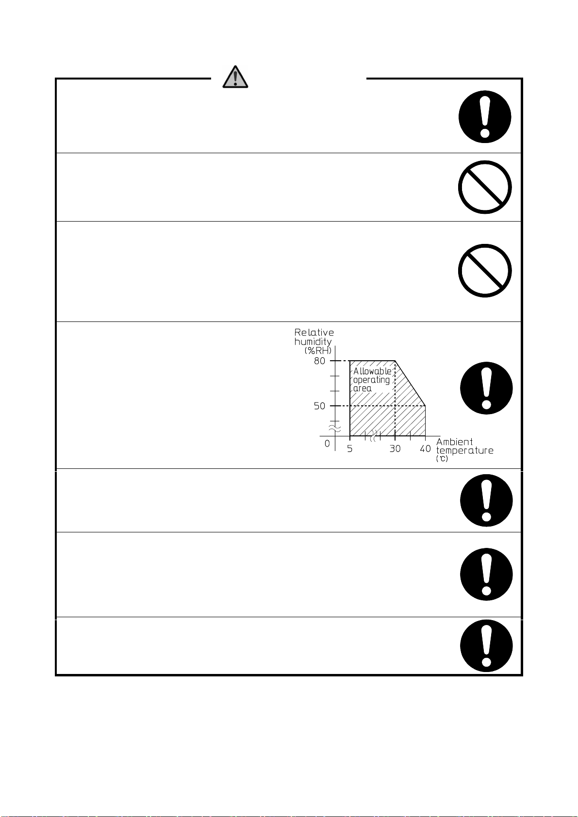
Mount, wire, adjust and service
the product under conditions shown in
the chart on the right.
Not observing this may result in product
damage.
Turn off the equipment before wiring or inspection. Otherwise
leakage or short circuit may cause ignition or electric shock.
After wiring is complete, always check for its correctness. Wrong
wiring may cause:
- damage to or malfunction of the equipment or connected devices;
- ignition;
- electric shock or user injury.
Turn off the equipment immediately in case smoke, unusual smells
or sounds are noticed. Do not supply power until problems are
solved.
- ADD 3 -
CAUTION
Handle the equipment with care. Do not drop, throw, or give
a strong shock to avoid damage.
Observe operation conditions specified in the manual. Use outside
the specified conditions may result in malfunction of or damage to
the equipment or connected devices, ignition, user injury, or
electric shock.
Perform operation tests before actual application to ensure
performance. Install back-up instruments based on different
technologies if failure of this equipment is expected to result in
a serious incident.
Check carefully for chemical compatibility of materials of
construction before installation.
Use the flange, thread or somewhere close to the process
connection to handle the equipment. Do not use the housing to
avoid dropping the equipment, and resultant damage to the
equipment or user injury.
Equipment 50cm or longer:
Lay the equipment when not in use. Otherwise it may fall and
damage itself or things around it, and cause user injury.
Always ground the equipment. (Grounding resistance: 100Ωmax.)
Without grounding, electric shock may occur in case excessive
voltage is applied to the housing.
When connecting to inductive or lamp loads:
Ensure the maximum voltage/current ratings will not be exceeded
to avoid damage to the relay contacts.
Use lightening arrestors or surge absorbers to prevent:
- malfunction, damage, or ignition of the equipment and connected
instruments;
- electric shock or injury.

- ADD 4 -
INTRODUCTION
A) This manual applies to standard models. Please note that information in
this manual may not be applied to customized versions.
B) We are willing to help customers select a suitable model or provide
information about chemical compatibility of materials used, but the
customer is responsible for the decisions made.
C) We always welcome suggestions and comments about this manual.
Please contact our sales office when you have questions or comments.
D) Component replacement:
The equipment design is regularly reviewed and improved. The same
components therefore may not be available when replacement is required.
In such cases, different components or products may be supplied. Please
contact our sales office for detail.
E) The contents of this manual are subject to change without prior notice as
a result of improvement of the equipment.
WARRANTY & DISCLAIMER
A) Nohken warrants the equipment against defect in design or material, and
workmanship for a period of one (1) year from the date of original
shipment from Nohken’s factory.
B) Nohken will not assume liability for loss nor damage resulting from the
use of the equipment.
C) Nohken will not assume liability for damage resulting from:
C-a) not observing instructions in this manual;
C-b) installation, wiring, operation, maintenance, inspection, or storing in
a manner not outlined in this manual;
C-c) unauthorized alterations and repairs;
C-d) the use of or replacement with components not provided by Nohken;
C-e) devices or instrument other than those manufactured by Nohken;
C-f) the use not described in Chapter 1 Purpose of Use of the manual;
C-g) force majeure including, but not limited to, fire, earthquake, tsunami,
lightning strike, riot, commotion, war, armed conflict or terrorist
attack, radioactive pollution, act of God, governmental decisions or
actions, and compliance with laws and regulations.
THE PROVISIONS OF THIS SECTION DO NO LIMIT YOUR LEGAL RIGHTS.

Table of Contents
1.PURPOSE OF USE
…………………………………………… 1
2.DESCRIPTION
…………………………………………… 1
2.1 Description …………………………………………… 1
2.2 Principle of Operation …………………………………………… 1
3.SPECIFICATIONS
…………………………………………… 1
3.1 Model Code …………………………………………… 1
3.2 Specifications …………………………………………… 2
3.3 Outline Drawing …………………………………………… 3
4.HANDLING NOTES
…………………………………………… 4
5.INSTALLATION
…………………………………………… 5
5.1 Unpacking …………………………………………… 5
5.2 Mounting …………………………………………… 6
6.WIRING
…………………………………………… 10
6.1 Before Wiring …………………………………………… 10
6.2 Wiring …………………………………………… 11
6.3 Cable Inlet …………………………………………… 12
6.4 Operation Check …………………………………………… 12
6.5 Placing the Cover …………………………………………… 12
7.PART NAME AND FUNCTION
…………………………………… 13
8.OPERATION
…………………………………………… 14
8.1 Tools Used for Sensitivity Adjustment/Check ………………………………… 14
8.2 Notes on Sensitivity Adjustment/Check ………………………………………… 14
8.3 Adjusting Sensitivity …………………………………………… 15
9.MAINTENANCE AND INSPECTION
……………………… 17
9.1 Removing from Process …………………………………………… 17
9.2 Maintenance …………………………………………… 18
9.3 Mounting …………………………………………… 18
9.4 Wiring …………………………………………… 18
9.5 Component Replacement …………………………………………… 18
9.6 When to Replace …………………………………………… 18
10.STORING
…………………………………………… 19
11.TROUBLESHOOTING
…………………………………………… 20
12.GLOSSARY
…………………………………………… 21
-1-
1. PURPOSE OF USE
This product is designed to detect fine powders, solids, granular materials, bulk solids or sludge
blanket at a desired level, and send signals. The signals are used to trigger alarms or control
electromagnetic switches. Do not use the product for any other purpose.
2. DESCRIPTION
2.1 Description
The product is mounted on a hopper using the threaded or flanged connection. When the material
reaches the detecting pipe*, the relay inside the housing makes or breaks contact.
2.2 Principle of Operation
The product has a detecting pipe that incorporates a magnet and an electromagnet. The pipe
is vibrated by means of these magnets. Current that flows on the electromagnet decreases
when the pipe is covered by the material. The product detects this difference in current
value on the electromagnet, and sends electric signals.
Fig. 2-1
3. SPECIFICATIONS
3.1 Model Code
① ② ③
VL □□ □ □-CE
③ Temperature
(blank) standard
T high temperature
② Mounting
N threaded
F flanged
G guard flanged
① Detecting pipe
13 standard
23 long
33 flexible
* See chapter 12 GLOSSARY.

-2-
3.2 Specifications
Table 3-1
Product Vibrating Level Sensor
Model VL13N, F, G (T) VL23N, F, G (T) VL33F
Measured Material solids, granular materials, bulk solids,
sludge blanket (excluding VL33)
Operating Characteristics
Sensitivity Bulk density ≧ 0.2 (excluding sludge blanket applications)
Operation indicator Power: green LED, Energized relay: red LED
Startup behavior Relay de-energized for approx. 15 seconds after power-up
Vibration Approx. 300 to 500Hz
Electric Characteristics
Power supply 100 to 240V AC±10%, 50/60Hz
24V DC ±10%
Power consumption Approx. 2VA at 100V AC (excluding startup)
Approx. 5VA at 240V AC (excluding startup)
Approx. 1W at 24V DC
Relay output Dry contact (SPDT)
Relay energized/de-energized at detection (switchable)
Delay time: 3 to 5 seconds when set
3 to 5 seconds when reset
Contact ratings Maximum: 250V, 3A AC / 30V, 3A DC (resistive load)
Minimum: 5V, 10mA DC (resistive load)
Insulation resistance 100MΩ Min. at 500V DC, between each terminal and housing
(excluding protective earth)
Withstand voltage 2200V AC for 5 seconds, between each terminal and housing
(excluding protective earth)
Overvoltage protection Overvoltage category Ⅲ
Pollution degree 4
Mechanical Characteristics
Withstand pressure
(static) 2MPa Max. (excluding process connection) 1kPa Max. (excluding
process connection)
Lateral load 0.55kN Max.(static) -
Tensile strength -1kN Max.
(extension tube)
Environmental
Working temperature
Wetted parts -20 to +150℃ (standard)
-20 to +180℃ (high temperature) -20 to +70℃
Housing -20 to +60℃ (no dew condensation)
Humidity 95% RH Max.
Altitude 2000m Max.
Protection class
Wetted parts IP68 or equivalent IP65 or equivalent
Housing IP65 or equivalent
Material
Wetted parts
304 stainless steel 304 stainless
steel, silicone
304 stainless steel,
PVC(with steel core),
NBR, POM, silicone
Housing Aluminum die casting (acrylic coated)
Cable inlet G 3/4 or equivalent
-3-
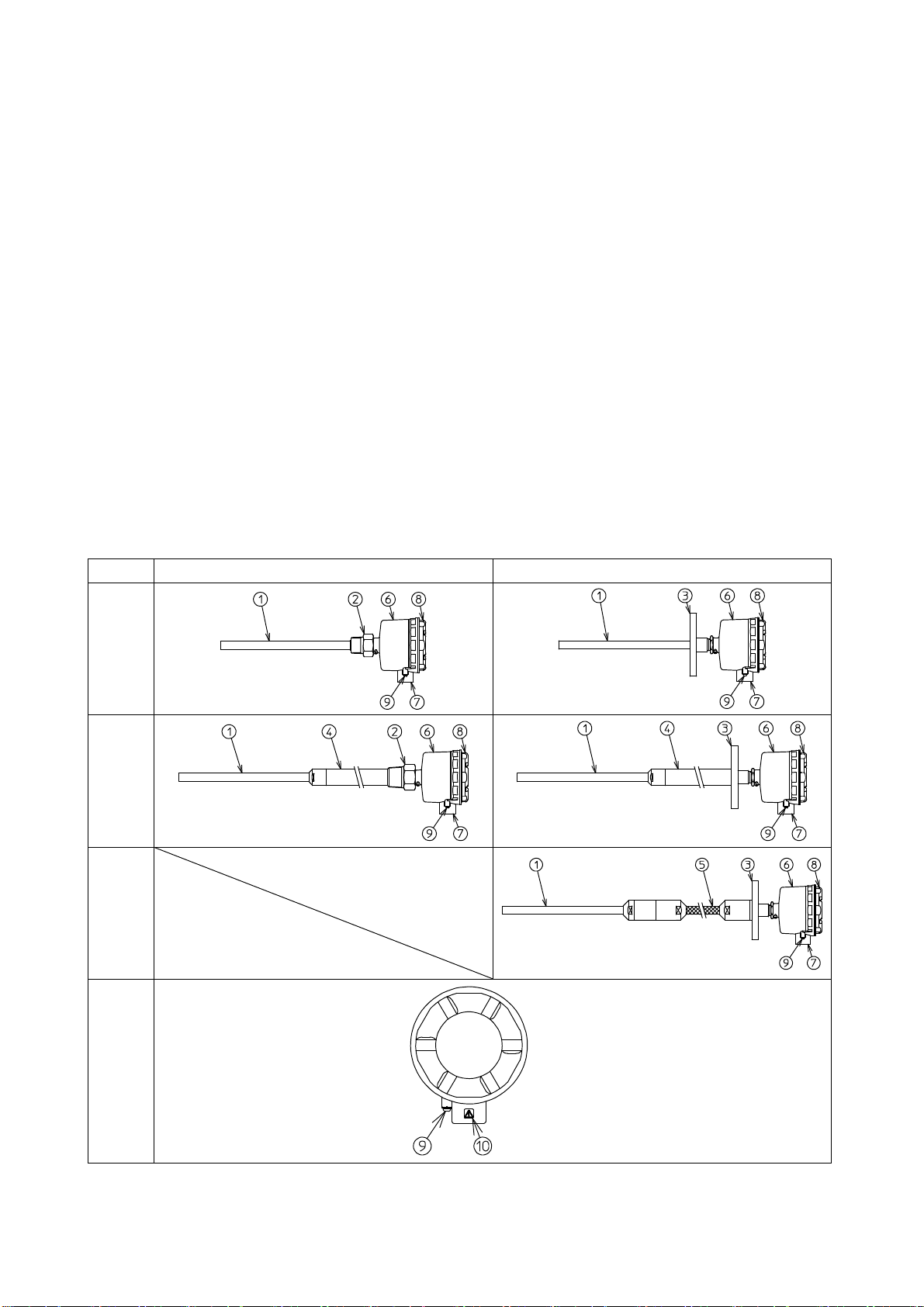
3.3 Outline Drawing
① Detecting pipe
Directly contacts material and detects it. Vibrates without contacting material.
Vibration decreases as material covers the pipe.
② Threaded connection (VL13N/T, VL23N/T)
Process connection to mount the sensor on a hopper.
③ Flange (VL13F/T, 23F/T, 33F)
Process connection to mount the sensor on a hopper.
④ Extension pipe (VL23N/T, VL23F/T)
Component to extend measurement range.
⑤ Extension tube (VL33F)
Component to extend measurement range.
⑥ Housing
Enclose electric circuit.
⑦ Cable inlet
Size: G3/4 or equivalent
⑧ Cover
Cover for the housing.
⑨ External earth terminal
Terminal to ground the product.
⑩ Warning sign
Indication to reference the first warning on page ADD 2 of this manual.
Model Threaded type Flanged type
VL13
VL23
VL33
Common Top view
Fig. 3-1
-4-
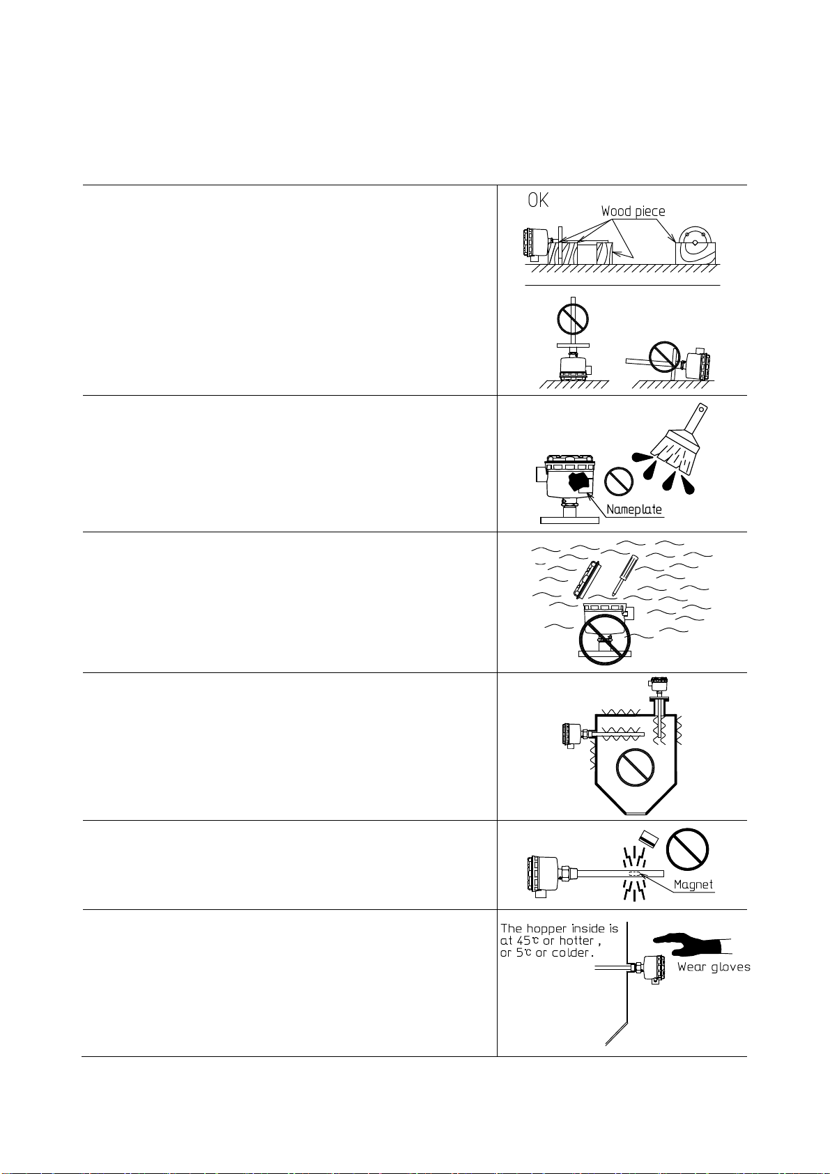
4. HANDLING NOTES
Observe instructions below when handling the product, or faulty operation or user injury may
result.
(1)
Lay the product on a flat surface to prevent it from
falling down. Provide support such as wo
od pieces
beneath the product to prevent it from rolling and
damaging the detecting pipe. Be extra-
careful not to
damage the pipe.
(2) Nameplate contains important information for
maintenance and other services. Ensure such
information is legible when painting the product.
(3) Avoid corrosive atmosphere (NH3, SO2, Cl2) for
installation, wiring, maintenance or adjustment.
Such atmosphere will enter inside when the cover is
opened and corrode internal components.
(4) Avoid places subjected to e
xcessive vibration. If such
location is inevitable, remove the source or isolate
the sensor from vibration.
(5) The detecting pipe incorporates a magnet.
Ensure magnetic media and other devices are not
adversely affected by the magnetic field.
(6) Wear gloves before touching the housing or process
connection if the hopper inside is at 45℃ or hotter,
or 5℃ or colder. These components become hot/cold
enough to cause a burn/frostbite.
-5-
5. INSTALLATION
WARNING
This product is not of the explosion proof model*. Never use it in areas
where flammable or explosive gases or vapors are expected to be generated.
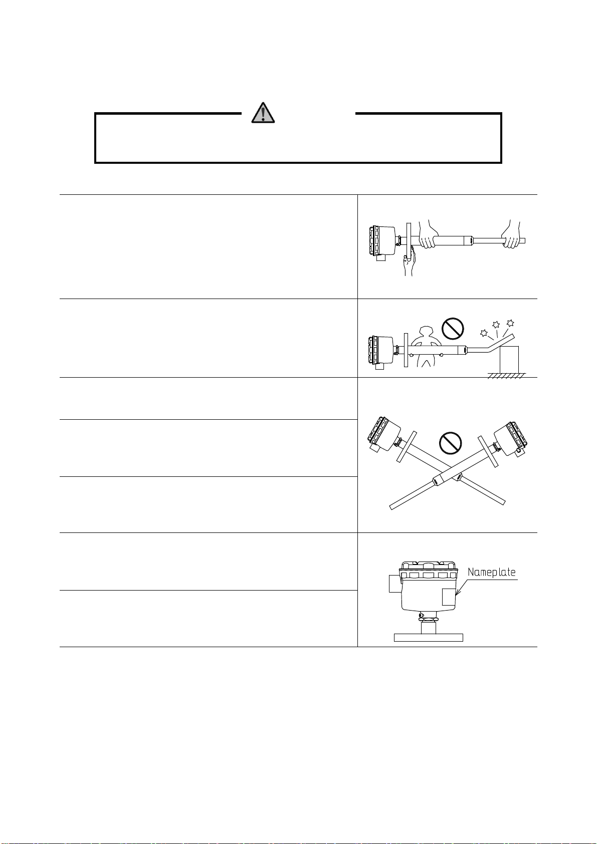
5.1 Unpacking
(1) Open the packaging and take out the product.
When handling the product, always hold the process
connection (threaded or flanged) or the part of pipe
close to the process connection, and somewhere else.
Otherwise the detecting pipe may bend due to the
heavy process connection and cause vibration failure.
(2) Products longer than 1500mm require two people to
carry them.
Otherwise the detecting pipe or the incorporated
vibration plate may be damaged by mistake.
(3) Do not drop, throw, crush, drag or give a shock to
the product to avoid damage.
(4) Completely remove tape, vinyl, cupboard and other
packing material.
Otherwise they may cause faulty operation.
(5) Do not place anything on the product to avoid
applying undesirable force to or deforming the
product.
(6) Check against the nameplate if the product is as
you have ordered. If not, please contact our sales
office.
(7) Check the product for damage.
If any, it may have been caused during transport.
Please contact our sales office.
* See chapter 12 GLOSSARY.

-6-
5.2 Mounting
5.2.1 Mounting location
Ensure ample space above and around the mounting point
for easy handling and maintenance. Note that the space
between ceiling/wall and the hopper must be large
enough to accommodate overall length of the product.
This must be ensured after the product is mounted for
future maintenance. (Fig. 5-1)
Also observe the following instructions, otherwise
faulty operation may result.
Fig. 5-1
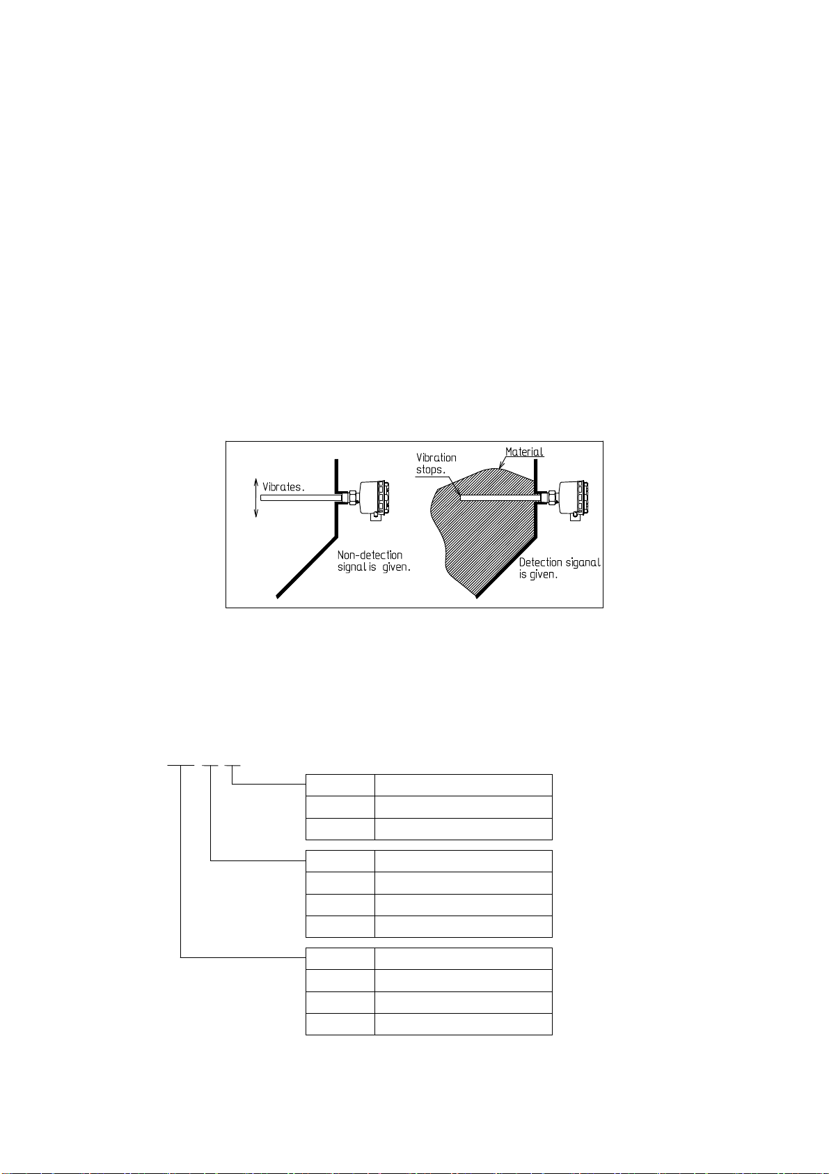
(1) Beware of the angle of repose*.
Avoid locations where the material does not reach
the detecting pipe. (Fig. 5-2)
Fig. 5-2
(2) Avoid locations where vibration occurs.
Mounting close to a vibrator*or a knocker*may
cause malfunction or damage the product.
(Fig. 5-3)
Fig. 5-3
(3) Avoid areas susceptible to deposit*to prevent
faulty operation. (Fig. 5-4)
Fig. 5-4
* See chapter 12 GLOSSARY.
-7-
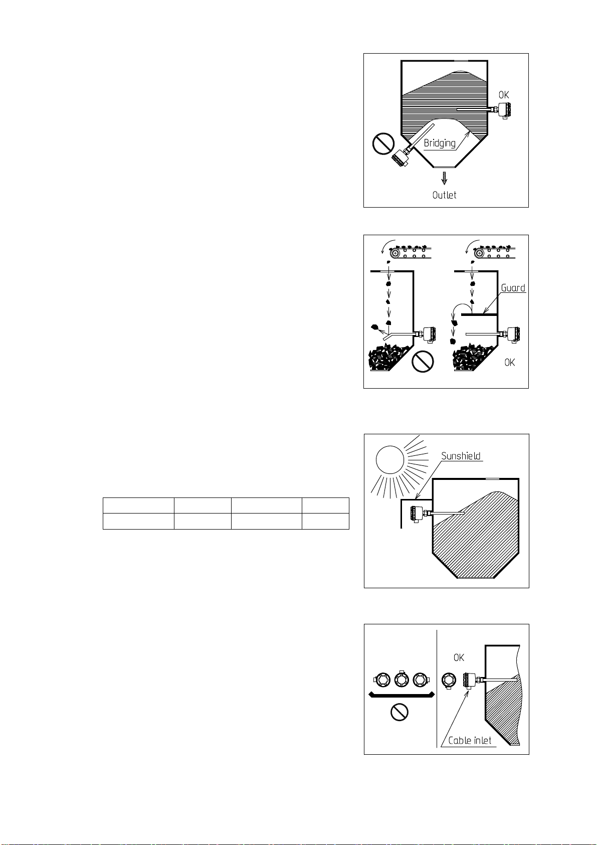
(4) Beware of bridge formation*.
Avoid locations adversely affected by bridging.
Ensure the product will not be damaged when the
bridge falls. (Fig. 5-5)
Fig. 5-5
(5) Avoid fill path to prevent faulty operation and
product damage.
Provide a guard*above the product, if necessary.
(Fig. 5-6)
Fig. 5-6
(6) Avoid locations where temperature becomes high.
High temperatures may cause faulty operation.
The chart below shows maximum temperatures for
wetted parts and the housing.
Wetted parts
Model VL13, 23 VL13T, 23T VL33
Temperature +150℃ +180℃ +70℃
Housing: +60℃
(7) Avoid exposure to direct sunlight. In summer
especially, direct sunlight causes internal Fig. 5-7
temperature to exceed the ratings. Provide a
sunshield*if necessary. (Fig. 5-7)
(8) Properly tighten the cover and treat the cable
gland. Water entering inside may cause faulty
operation. The IP rating (IP65 or equivalent) is
achieved only when the cover is properly tightened
and the cable inlet properly treated.
If the product is mounted horizontally, ensure the
cable inlet points downwards. (Fig. 5-8)
Fig. 5-8
* See chapter 12 GLOSSARY.

-8-
(9) Ensure lateral load applied to the detecting pipe
will not exceed the rating. Maximum load at the
end of the pipe (φ17.3mm, 270mm long) is 0.55kN
(static load). Load greater than this may cause
faulty operation or product damage. (Fig. 5-9)
In applications where material rapidly moves or
excessive load is expected, provide a guard*
(Fig. 5-6), or mount the product at an angle to
avoid load.
Fig. 5-9
(10) Do not mount VL33 (flexible type) horizontally, or
faulty operation may result.
(11) Ensure the detecting pipe (φ17.3mm, 270mm long)
will not contact standpipe wall, hopper bottom or
walls to avoid faulty operation.
(12) Do not mount VL23 (long type) longer than 1m
horizontally. Otherwise the extension pipe may be
bent or come off due to material load. (Fig. 5-10)
Fig. 5-10
(13) Use a standpipe as short as possible and ensure
material will not remain inside. Ensure the
detecting pipe projects into the hopper for at
least 200 mm. For a standpipe of size 50A and sch20,
the maximum length is 70mm. Note that the maximum
length depends on material properties and
standpipe size. (Fig. 5-11)
Fig. 5-11
(14) Avoid corrosive atmosphere. Detecting pipe is in stainless steel (304 stainless steel
as standard), but most of the electronic components inside the housing uses cupper lead
wire. Corrosive atmosphere may attack lead wire and break it, resulting in faulty
operation.
(15) If the extension pipe of VL23 (long type) needs to be secured, please contact our sales
office.
* See chapter 12 GLOSSARY.
-9-
5.2.2 Mounting the Products
(1) Flanged units
Fit the hopper flange and the product flange, and secure them using bolts according to
standards and a suitable tool. Use a gasket in pressure applications to prevent leak.
Note that bolts and gaskets are optional parts.
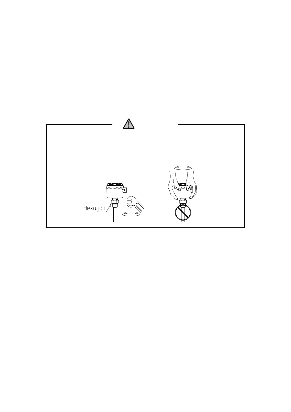
(2) Threaded units
Secure the product using a suitable tool. Always rotate the hexagon above the threaded
connection and never the housing. Using the housing may apply excessive force and break
wiring inside the housing. For pressure applications, use sealing material on the thread
to prevent leak.
CAUTION
When removing the threaded unit from the hopper, rotate the hexagon above
the
threaded connection with a suitable tool. Never rotate the housing, otherwise
connection between the housing and the threaded connection will be
loosened,
breaking internal wiring or sealing.
- 10 -
6. WIRING
6.1 Before Wiring
(1) Disconnect power to cabling.
WARNING
Disconnect power before wiring. Otherwise electric shock, or ignition or human injury
due to leakage or short circuit of energized parts may result.
(2) Use cable rated for 35℃ higher than the rated temperatures for the housing.
The cable inlet accommodates cables of 10 to 18mm in diameter.
Suitable conductor sizes are:
0.75 to 2mm2for terminal block
2 to 3.5mm2for protective earth and external earth terminal on the housing
(3) Always provide a power switch and a fuse close to the product. Connect the fuse to
L1+ (Live) line (Fig.6-3). Indicate these components are used for the product.
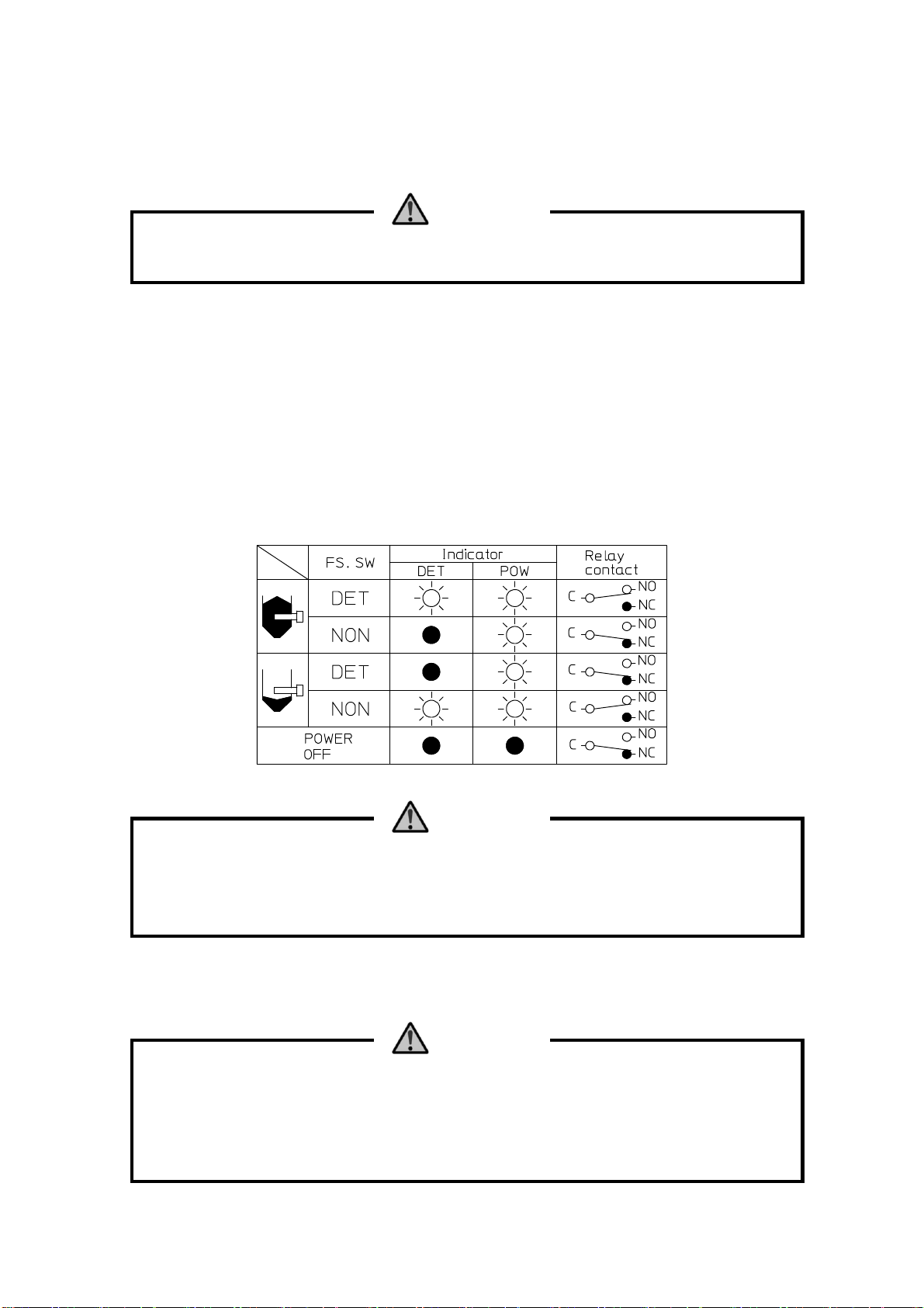
(4) Relay wiring
Fail-safe setting determines relay operation. See Fig. 6-1.
Fig. 6-1
CAUTION
Relay ratings are 250V, 3A AC (resistive) or 30V, 3A AC (resistive)
. Do not exceed
these ratings, or relay contacts may be damaged. Provide a suitable relay between
the load and the output terminals of the product when switching loads that
exceed
the product ratings.
(5) Grounding
Always ground the protective earth (PE) inside the housing.
(grounding resistance: 100Ω Max.)
CAUTION
Always ground the protective earth (PE)
inside the housing (grounding resistance:
100Ω Max.). Without grounding, electric shock or injury may result due to high
voltages on the housing in case of the power line contacting the housing.
Ground the external earth terminal on the housing when necessary (grounding
resistance: 100Ω Max.).
(6) Remove the cover of the sensor housing.
- 11 -
6.2 Wiring
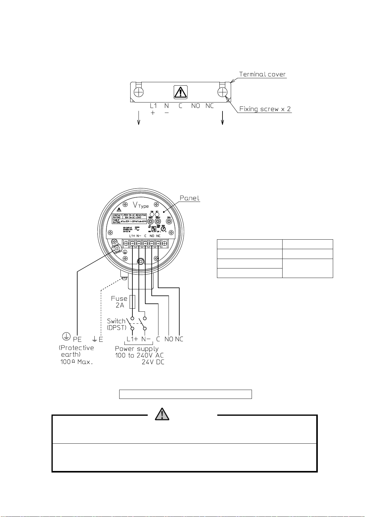
(1) Loosen the two fixing screws on the terminal cover, and remove the cover.
Do not lose the cover as it is used after wiring is complete.
Fig. 6-2
(2) Figure 6-3 shows wiring diagrams. Use a suitable tool when wiring.
Terminal screws are of M3.5. Use cable lug of R1.25-3.5 or equivalent size.
The screws of protective earth (PE) and the external earth terminal on the housing are
of M4. Use cable lugs of R1.25-4 or equivalent size.
Terminal Torque
Terminal block 1.0 N・m Max.
Protective earth 1.2 N・m Max.
External earth
Fig. 6-3
This product is polarity insensitive.
WARNING
The panel prevents contact with the internal circuit. Never remove it.
Voltages exceeding the rating may result in product damage or injury due to
overvoltage on the product.

- 12 -
(3) Place the terminal cover, and secure it with the two fixing screws.
Fig. 6-4
6.3 Cable Inlet
Cable inlet is of G 3/4 or equivalent size.
Use a cable gland or a conduit to secure the cable. In either case, lead the cable downward
in front of the cable inlet to prevent water entry.
Secure the cable using a sealing compound when a conduit is used, and by tightening the gland
with a suitable tool when a cable gland is used, to prevent entry of dust, debris or rain
into the housing. If water or moisture can enter from inside the conduit, putty the inside.
(Fig. 6-5)
Fig. 6-5
6.4 Operation Check
(1) Remove dust and debris from the housing. Ensure metal debris is not left since it may
cause shortcircuit.
(2) Before actual operation, fill the hopper with the material and check product performance.
If the product does not operate as it should, check for incorrect wiring, and read this
instruction manual once again. Please contact our sales office for any questions.
6.5 Placing the Cover
Properly tighten the cover on the housing. If loose, rain or dust may enter and corrode
inside components, causing short circuit or faulty operation.
OK OK

- 13 -
7. PART NAME AND FUNCTION
Fig. 7-1
① Terminal block
For power and relay output connection.
② Power lamp [POW]
Lights when powered. (green LED)
③ Alarm lamp [DET]
Lights when relay is energized. (red LED)
④ Vibration check terminal [VIBR(+)]
Gives output of 0 to 5V DC that represents sensor vibration level.
⑤ Sensitivity check terminal [SENS(+)]
Gives output of 0 to 5V DC that represents sensitivity level.
⑥ COM terminal [COM(-)]
Negative terminal used to check vibration or sensitivity level.
⑦ Sensitivity trimmer [SENS]
Sets sensitivity level.
⑧ Sensitivity range switch [RANGE]
Switches high and standard sensitivity ranges.
⑨ Fail-safe switch [FS]
Reverses output signals.
⑩ Protective earth terminal
Grounds the product. Connect this terminal to ground.
(Grounding resistance: 100Ω Max.)

- 14 -
8. OPERATION
This product is basically adjustment free. Use them in the as-delivered state. Changing switch
or trimmer setting may cause faulty operation.
Sensitivity adjustment may be necessary when:
- Material has low bulk density or high fluidity, and the product cannot detect the level.
- Material builds up on the detecting pipe and erratic signals are sent.
- Switch is switched or trimmer turned accidentally.
In these cases, follow instructions below and make adjustment.
8.1 Tools Used for Sensitivity Adjustment/Check
- Digital tester for measuring 0 to 5V DC and with input resistance 1MΩ or greater. Analog
testers and voltmeters can also be used if their input resistance is 1MΩ or greater.
- Slotted screwdriver for sensitivity trimmer. Slot on the trimmer is 0.7mm x 5mm.
8.2 Notes on Sensitivity Adjustment/Check
CAUTION
Sensor output may switch during adjustment. Ensure controlled devices
are not
adversely affected.
The product gives detection signal when voltage at the vibration check terminal*undershoots
voltage at the sensitivity check terminal*.
Voltage at the vibration check terminal decreases when detecting pipe vibration is restricted
by material. The tighter the restriction, the further the voltage decreases. This means high
voltages at the sensitivity check terminal result in high sensitivity level, and vice versa.
Voltage at the sensitivity check terminal is changed using the sensitivity range switch and
the sensitivity trimmer. Fig. 8-1 shows how the voltage changes.
Fig. 8-1
* See chapter 12 GLOSSARY.
This manual suits for next models
15
Table of contents
Other Nohken Accessories manuals


