NOJA Power GMK-1000 Series User manual


NOJA-7343-03
Revision History
Rev
Author
Date
Comment
0
OA
17-08-15
Initial Release
1
OA
10-09-15
Added 15kV recloser.
2
OA
14-09-16
Updated Part Numbers
3
OA
02-12-16
Updated Fault Break Capacity operations.
NOJA Power®and OSM®are registered trademarks of NOJA Power Switchgear Pty Ltd. This
document is copyright and is intended for users and distributors of NOJA Power Switchgear product. It
contains information that is the intellectual property of NOJA Power Switchgear and the document, or any
part thereof, should not be copied or reproduced in any form without written permission from NOJA Power
Switchgear.
NOJA Power®and OSM®are registered trademarks of NOJA Power Switchgear and should not be
reproduced or used in any way without written authorisation.
NOJA Power Switchgear applies a policy of ongoing development and reserves the right to change product
without notice. NOJA Power Switchgear does not accept any responsibility for loss or damage incurred as a
result of acting or refraining from action based on information in this User Manual.
© NOJA Power Switchgear Pty Ltd 2002 - 2017
www.nojapower.com.au

NOJA-7343-03
CONTENTS
INTRODUCTION .................................................................................................................................................................1
APPLICABILITY ........................................................................................................................................................................... 1
SAFETY..................................................................................................................................................................................... 1
SPECIFICATIONS.................................................................................................................................................................2
RATINGS................................................................................................................................................................................... 2
IP RATINGS............................................................................................................................................................................... 3
DIMENSIONS AND WEIGHT .......................................................................................................................................................... 3
DRAWINGS ........................................................................................................................................................................4
INSTALLATION ...................................................................................................................................................................6
MOUNTING DETAILS................................................................................................................................................................... 6
LIFTING POINTS ......................................................................................................................................................................... 7
CABLE ENTRIES .......................................................................................................................................................................... 9
DEAD BREAK ELBOWS ............................................................................................................................................................... 10
EARTH SADDLE ........................................................................................................................................................................ 10
EARTH BAR ............................................................................................................................................................................. 11
RECLOSER CONTROL (RC10) CUBICLE ...............................................................................................................................12

NOJA-7343-03
1
Ground Mount Kiosk (GMK-1000 Series)
User Manual
INTRODUCTION
The NOJA Power Ground Mounted Kiosk (GMK) is designed for the connection and protection of underground
cables for voltages up to 27kV.
The kiosk houses an OSM Automatic Circuit Recloser and an RC-10 Controller.
This document provides the following information for the GMK:
Specification
Drawings
Installation Details.
For more details on the features provided by the RC-10, please refer to the OSM User Manual.
APPLICABILITY
This manual covers the following product:
GMK15-16-1310.
GMK27-12-1310.
SAFETY
Installation, use and servicing should only be carried out by trained and experienced personnel who are familiar
with the equipment and electrical safety requirements.
Refer to OSM User Manual for Safety Information
NOJA-7343-03
2
Ground Mount Kiosk (GMK-1000 Series)
User Manual
SPECIFICATIONS
The GMK Reclosers, GMK15-16-1310 and GMK27-12-1310 have the same pole assembly and magnetic actuators
as the OSM 310 series reclosers.
The ratings are the same as the OSM15-16-800-310 and OSM27-12-800-310 with the exception of the rated
continuous current being 630A.
RATINGS
GMK Model
GMK15-16-1310
GMK27-12-1310
Rated maximum voltage
15.5 kV
27 kV
Rated continuous current
630 A
630 A
Fault make capacity RMS
16 kA
12.5 kA
Fault make capacity Peak (50Hz)
40 kA
31.5 kA
Fault make capacity Peak (60Hz)
42 kA
32.5 kA
Fault break capacity
16 kA
12.5 kA
Asymmetrical Breaking Current
17 kA
13 kA
DC component Interruption capacity
20%
20%
Mechanical operations
30000
30000
Full Load Operations
30000
30000
Fault break capacity operations
70
140
Short time current withstand 3 seconds
16 kA
16 kA
Mainly active breaking capacity
630 A
630 A
Cable charging current
25 A
25 A
Line charging current
5 A
5 A
Impulse withstand across the interrupter
110 kV
150 kV
Impulse withstand phase to earth and phase to phase
110 kV(1)
150 kV(1)
Power frequency withstand phase to earth (dry) and across
the interrupter
50 kV
60 kV
Closing Time
<60 ms
<60 ms
Opening Time
<30 ms
<30 ms
Interrupting Time
<50 ms
<50 ms
Ambient Temperature
- 40° C to + 55° C
- 40° C to + 55° C
Input AC Voltage
110/220Vac
110/220Vac
Note 1: Subject to the rating of the Dead Break Elbow connectors installed (not supplied).

NOJA-7343-03
3
Ground Mount Kiosk (GMK-1000 Series)
User Manual
IP RATINGS
The IP ratings are as follows:
IP65 for the controller compartment
IP54 for the customer equipment compartment
IP65 for the OSM310-GMK
IP54 for the OSM + Cable Compartment.
DIMENSIONS AND WEIGHT
Dimensions
1225 x 1341 x 1160 mm
Weight
480kg

NOJA-7343-03
4
Ground Mount Kiosk (GMK-1000 Series)
User Manual
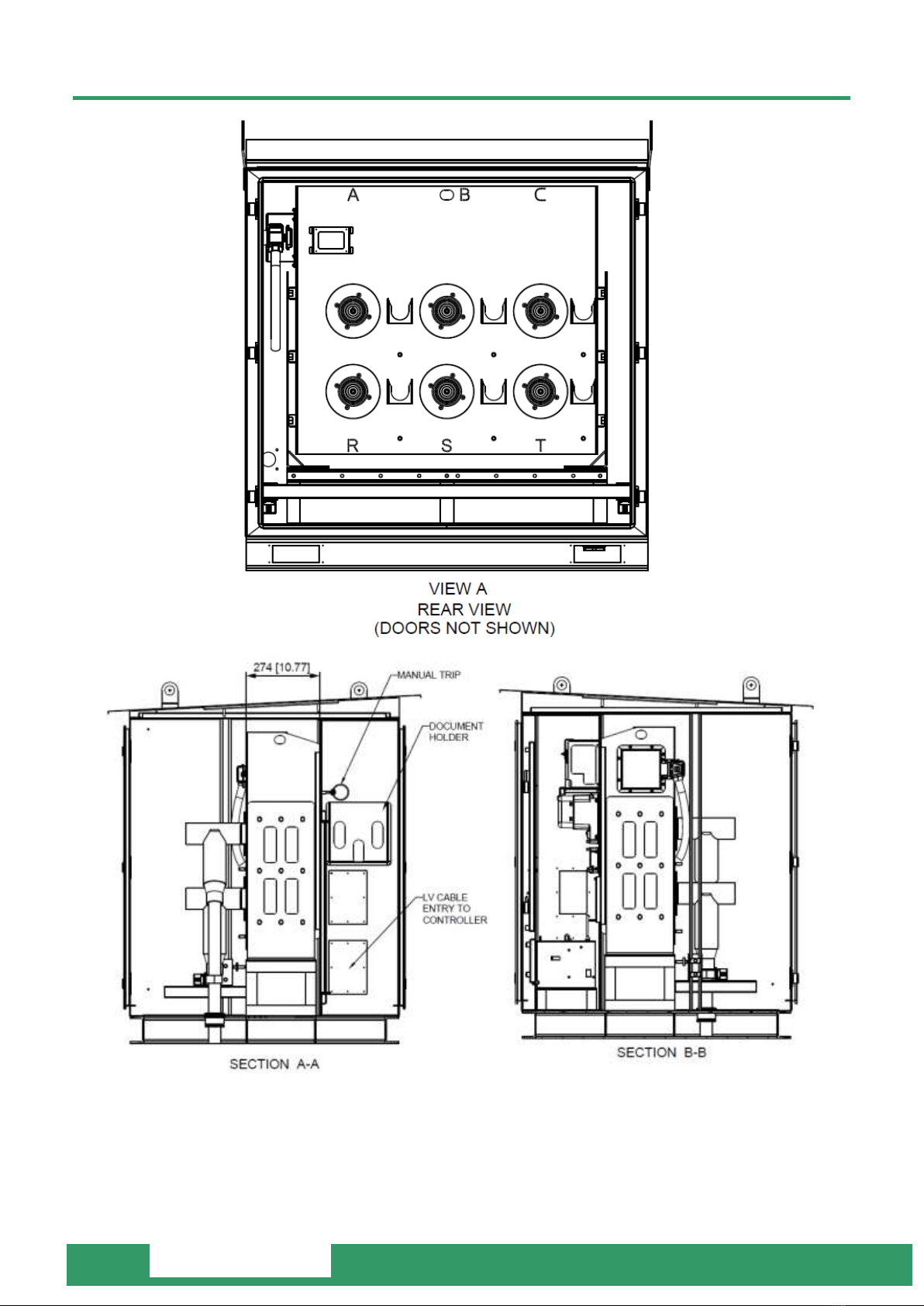
DRAWINGS
Note: The GMK is supplied with a blank radio equipment tray. Suitable mounting holes have to be drilled prior
to use.
NOJA-7343-03
5
Ground Mount Kiosk (GMK-1000 Series)
User Manual
Note:
The manual trip ring is located in the customer equipment compartment, next to the open/close
indicator window.
LV supply is through the gland plate on the partition wall.
NOJA-7343-03
6
Ground Mount Kiosk (GMK-1000 Series)
User Manual
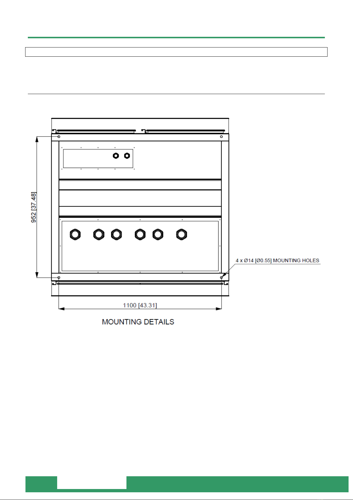
INSTALLATION
A cable pit must be built for the GMK. A concrete base is recommended.
MOUNTING DETAILS
The GMK has 4 x 14mm diameter mounting holes which can be used for bolting the GMK to the ground.
NOJA-7343-03
7
Ground Mount Kiosk (GMK-1000 Series)
User Manual
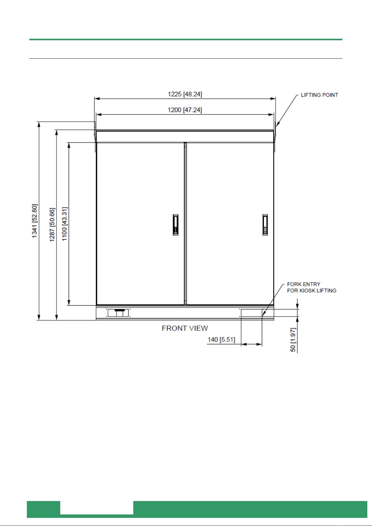
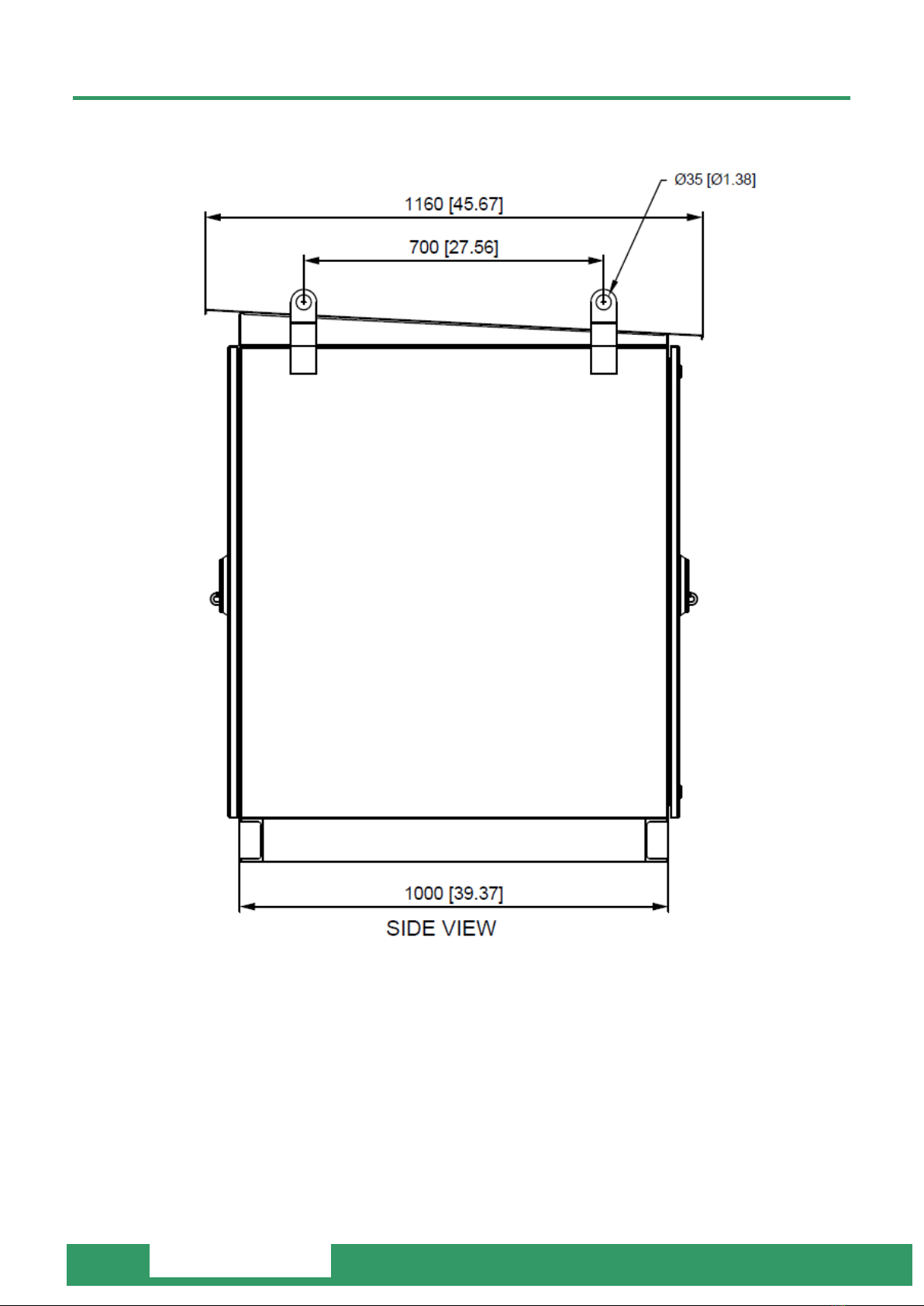
LIFTING POINTS
Fork entry holes, 140 x 50mm are available at the bottom of the unit as shown. Where no forklift is available,
the GMK can be lifted through the lifting points welded on the enclosure body using slings and a crane.
NOJA-7343-03
8
Ground Mount Kiosk (GMK-1000 Series)
User Manual

NOJA-7343-03
9
Ground Mount Kiosk (GMK-1000 Series)
User Manual
CABLE ENTRIES
The GMK is supplied with blank aluminium gland plates for HV, LV and Earth cable entries. Holes must be
drilled to suit the compression glands of incoming cables.

NOJA-7343-03
10
Ground Mount Kiosk (GMK-1000 Series)
User Manual
DEAD BREAK ELBOWS
Dead Break Elbow connectors must be Interface Type C to DIN EN 50181. The model of the connector will vary
depending on many factors including cable voltage, current ratings, conductor size and the diameter over the
core insulation. These factors should be taken into consideration when selecting a connector.
Installation of Dead Break Elbows is brand specific. Please refer to the installation manual of the dead break
elbow for detailed instructions. For a generic guide refer to NOJA-7320 Dead Elbow Connector Installation
Instructions.
Note: Our supplied product which does not include termination such as dead break elbows is rated at 150kV
BIL.
EARTH SADDLE
The Earth Saddles are used to support earth conductors with a stand-off Type C interface when elbow
connections are removed from the poles during maintenance. The interface can be earthed through the studs
below the saddles.

NOJA-7343-03
11
Ground Mount Kiosk (GMK-1000 Series)
User Manual
EARTH BAR
The GMK enclosure, recloser and RC10 components are connected to earth through the earth bar located at the
bottom of the recloser.
A cable entry has to be prepared on the HV gland plate to suit the incoming main earth cable which will be then
connected to the earth bar.
The earth bar comes with M12 nut and bolt that can be used in connecting the main earth cable.

NOJA-7343-03
12
Ground Mount Kiosk (GMK-1000 Series)
User Manual
RECLOSER CONTROL (RC10) CUBICLE
Please refer to the OSM User Manual.
This manual suits for next models
2
Table of contents
Popular Industrial Electrical manuals by other brands

Murata
Murata GRM1885C2A390JA01 Series Reference sheet

Murata
Murata GRM0335C1E330JA01 Series Reference sheet

Murata
Murata GRM1885C1H470JA01 Series Reference sheet

Murata
Murata GRM0225C1E2R4CDAE Series Reference sheet

Murata
Murata GRM3195C1H223JA01 Series Reference sheet

Phoenix Mecano
Phoenix Mecano Lambda Assembly instructions


