manuals.online logo
Brands
  1. Home
  2. •
  3. Brands
  4. •
  5. Wen
  6. •
  7. Industrial Electrical
  8. •
  9. Wen 418CV User manual

Wen 418CV User manual

INSTRUCTION MANUAL
MODEL 418CV
ÉTAU POUR PERCEUSE
8-3/8-INCH
CROSS VISE
PARTS
Fig. 1
Top View
Fig. 2
Top View
ASSEMBLY
1. Remove all components and parts from the box. Your cross vise includes the following
hardware:
• (3) Hex Wrenches
• (2) Locking Nuts
• (2) Flat Washers
• (2) Crank Handles
2. If necessary, adjust the longitudinal (top) feed screw until the handle-mounting portion of
the feed screw protrudes beyond the vise body, as shown in Fig. 1 below. Turning the feed
screw clockwise retracts it; turning it counterclockwise advances it. Turn the feed screw fully
clockwise until it can no longer retract.
3. Mount one of the crank handles on the leadscrew, as shown in Fig. 2 below.
4. Secure the crank handle to the feed screw using the included at washer and locking nut (Fig.
2). Tighten the nut (turning clockwise) against the handle using a 10 mm socket (not included),
then back it off a quarter turn (turning counterclockwise). Turn the handle a couple of times. If
it is dicult to turn, loosen the nut. Adjust the nut as necessary to ensure that the handle turns
smoothly and advances the slide properly.
5. Repeat the same procedure to mount the remaining crank handle on the cross feed screw.
Crank Handle
Feed Screw
Flat Washer
Locking Nut
Clockwise Brings
Feed Screw Out
Counterclockwise
Sends Feed Screw
In
No. Part No. Description Qty.
1 416CV-001 Base 1
2 416CV-002 Nut 1
3 416CV-003 Saddle 1
4 418CV-004 Gib 2
5 416CV-005 Hex Nut, M6 6
6 416CV-006 Set Screw, M6x20 4
7 413CV-007 Flat Washer, M6 2
8 418CV-008 Longitudinal
Feed Screw 1
9 416CV-009 Cross Feed
Screw 1
10 416CV-010 Retaining Plate 1
11 416CV-011 Socket Head Bolt,
M8x20 4
12 416CV-012 Crank Handle
Assembly 2
No. Part No. Description Qty.
13 413CV-013 Locking Nut, M6 2
14 418CV-014 Leadscrew With
Handle 1
15 418CV-015 Guide Rod 1
16 418CV-016 Body 1
17 416CV-017 Socket Head Bolt,
M8x20 4
18 418CV-018 Movable Jaw 1
19 416CV-019 Dog Point Set
Screw, M8x10 1
20 418CV-020 Jaw Plate 1
21 418CV-021 Grooved Jaw
Plate 1
22 416CV-022 Retaining Plate 1
23 416CV-023 Set Screw, M6x25 2
24 416CV-024 Lock Washer, M6 4
25 414CV-025 Ball Bearing 1
INSTRUCTION MANUAL
ADJUSTMENT GUIDE
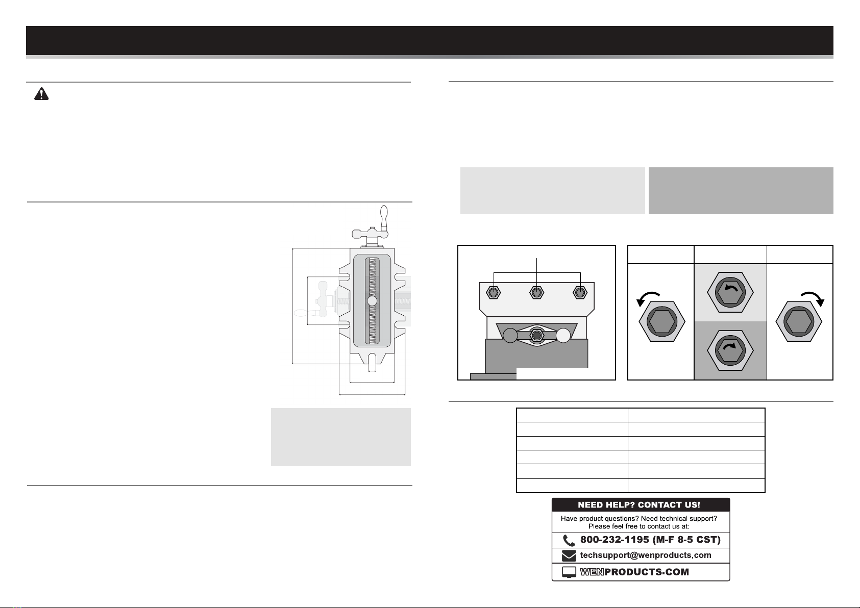
Your vise comes pre-adjusted from the factory, and should not require adjustment. However, if
the cross or longitudinal slides (Parts 1 & 16) are too tight or too loose, follow the steps below to
adjust them.
1. Locate the three gib screws on the side of the slide in question (Fig. 3).
2. Loosen the three hex nuts (Part 5), using a 10 mm wrench or socket (not included).
(Fig. 4 - Step 2)
MAINTENANCE
Acetone may irritate the skin. Wear gloves and eye protection when using acetone.
• Your vise comes with a layer of anti-rust protective coating on the machined surfaces. Remove
this coating with a clean cloth moistened with acetone, then protect the machined surfaces by
applying a light coat of good-quality paste wax.
• After using your vise, wipe it off with a cloth to ensure that no chips, shavings, or other debris
get into the way of your vise. Keep your vise clean. Periodically check the ways of the vise to
ensure that they are not blocked or damaged by chips, shavings, or other debris.
Gib Screws
3. IF THE SLIDE IS TOO TIGHT
• Loosen the set screws (Parts 6 & 23) using
the included hex wrench (Fig. 4 - 3A).
IF THE SLIDE IS TOO LOOSE
• Tighten the set screws (Parts 6 & 23) using
the included hex wrench (Fig. 4 - 3B).
4. Using the 10 mm wrench or socket, tighten the hex nuts (Part 5) back down. Make further
adjustments as needed.
Step 2 Step 3
B
A
Step 4
Fig. 3 Fig. 4
Side View
NOTE: To prevent the bolt from
loosening over time, use split
locking washers between at
washers, or use nylon locking
nuts.
MOUNTING INSTRUCTIONS
OPERATION
Follow the instructions below to safely and securely mount your
cross vise to a stable workbench. Mounting your vise eliminates
the risk of your vise moving or falling, allowing for more accuracy
and user safety.
1. Select a secure worktop to which your vise will be mounted,
such as a workbench. The workbench should be sturdy and
xed to the oor.
2. Find the best location on your worktop to mount your vise.
It is good to select a spot that allows access to both crank
handles, as well as the vise clamping handle (Part 14).
3. Once you have selected where you want to mount your vise,
use a pencil to mark the holes where the vise will be bolted
(four mounting anges are located on the base). You must
use at least two bolts that are diagonal from each other. Use
four bolts for optimum stability.
4. Move the vise to the side and use a drill to drill out the
marked spots for the bolts.
5. Line up the vise with the drilled holes. Insert bolts and
fasten. If the bolts extend through the bench, place a
washer and nut onto the end. Tighten nuts onto the bolts
using a wrench. (These bolts, washers and nuts are not
included).
Before operation, mount your vise and follow the assembly instructions on page 1 to attach the
handles.
1. Mark your workpiece for your specic job.
2. Rotate the leadscrew with handle counterclockwise to open the jaws. Place workpiece inside
of jaws in desired position. Rotate the handle clockwise to tighten the jaws and rmly secure
your workpiece.
3. To move the secured workpiece back and forth or side to side, rotate the lower and upper
handles.
SPECIFICATIONS
Jaw Capacity
8-3/8 in.
Cross Slide Travel 9.5 in.
Longitudinal Slide Travel 8.5 in.
Clamping Strength 3000 LBF
Dimensions 20-1/4 in. x 16-3/4 in. x 7-1/4 in.
Weight
74.9 lbs
0.66"
5.275"
7.69"
10.875"
6.625"

Other Wen Industrial Electrical manuals

Wen 416CV User manual

Wen

Wen 416CV User manual

Wen 413CV User manual

Wen

Wen 413CV User manual

Wen 415CV User manual

Wen

Wen 415CV User manual

Wen 414CV User manual

Wen

Wen 414CV User manual

Popular Industrial Electrical manuals by other brands

ABB Relion 670 series Commissioning manual

ABB

ABB Relion 670 series Commissioning manual

dymax BlueWave RediCure MX-250 Emitter user guide

dymax

dymax BlueWave RediCure MX-250 Emitter user guide

SEW-Eurodrive MOVIFIT basic manual

SEW-Eurodrive

SEW-Eurodrive MOVIFIT basic manual

Murata GRM033R61A104KE84 Series Reference sheet

Murata

Murata GRM033R61A104KE84 Series Reference sheet

Murata GRT21BC81C225KA02 Series Reference sheet

Murata

Murata GRT21BC81C225KA02 Series Reference sheet

GE QuiXtra 630 Assembly and mounting instructions

GE

GE QuiXtra 630 Assembly and mounting instructions

Bosch HCM 8 718 688 793 0 manual

Bosch

Bosch HCM 8 718 688 793 0 manual

PCB Piezotronics 478B05 Installation and operating manual

PCB Piezotronics

PCB Piezotronics 478B05 Installation and operating manual

Eltroplan REVCON RHD Series operating instructions

Eltroplan

Eltroplan REVCON RHD Series operating instructions

Murata GRM188R71E562KA01 Series Reference sheet

Murata

Murata GRM188R71E562KA01 Series Reference sheet

Murata GRM1555C2A2R7CA01 Series Reference sheet

Murata

Murata GRM1555C2A2R7CA01 Series Reference sheet

Murata GRM319R71C474KA01 Series Reference sheet

Murata

Murata GRM319R71C474KA01 Series Reference sheet

Murata GQM1555C2D3R4CB01 Series Reference sheet

Murata

Murata GQM1555C2D3R4CB01 Series Reference sheet

FOM alphaSC Operation & maintenance manual

FOM

FOM alphaSC Operation & maintenance manual

PCB Piezotronics 340A66 Installation and operating manual

PCB Piezotronics

PCB Piezotronics 340A66 Installation and operating manual

Festo FB16 Electronic manual

Festo

Festo FB16 Electronic manual

Murata GRM033C80G333KE01 Series Reference sheet

Murata

Murata GRM033C80G333KE01 Series Reference sheet

Murata GRM033C80J823ME15 Series Reference sheet

Murata

Murata GRM033C80J823ME15 Series Reference sheet

manuals.online logo
manuals.online logoBrands
  • About & Mission
  • Contact us
  • Privacy Policy
  • Terms and Conditions

Copyright 2025 Manuals.Online. All Rights Reserved.